

CME136686LX Hardware Manual - RTD Embedded Technologies ...
CME136686LX Hardware Manual - RTD Embedded Technologies ...
CME136686LX Hardware Manual - RTD Embedded Technologies ...

You also want an ePaper? Increase the reach of your titles
YUMPU automatically turns print PDFs into web optimized ePapers that Google loves.
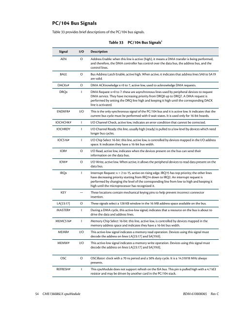
PC/104 Bus Signals<br />
Table 33 provides brief descriptions of the PC/104 bus signals.<br />
Signal I/O Description<br />
Table 33 PC/104 Bus Signals 1<br />
AEN O Address Enable: when this line is active (high), it means a DMA transfer is being performed,<br />
and therefore, the DMA controller has control over the data bus, the address bus, and the<br />
control lines.<br />
BALE O Bus Address Latch Enable, active high. When active, it indicates that address lines SA0 to SA19<br />
are valid.<br />
DACKx# O DMA ACKnowledge x=0 to 7, active low, used to acknowledge DMA requests.<br />
DRQx I DMA Request x=0 to 7: these are asynchronous lines used by peripheral devices to request<br />
DMA service. They have increasing priority from DRQ0 up to DRQ7. A DMA request is<br />
performed by setting the DRQ line high and keeping it high until the corresponding DACK<br />
line is activated.<br />
ENDXFR# I/O This is the only synchronous signal of the PC/104 bus and it is active low. It indicates that the<br />
current bus cycle must be performed with 0 wait states. It is used only for 16-bit boards.<br />
IOCHCHK# I I/O Channel Check, active low, indicates an error condition that cannot be corrected.<br />
IOCHRDY I I/O Channel Ready: this line, usually high (ready) is pulled to a low level by devices which need<br />
longer bus cycles.<br />
IOCS16# I I/O Chip Select 16-bit: this line, active low, is controlled by devices mapped in the I/O address<br />
space. It indicates they have a 16-bit bus width.<br />
IOR# O I/O Read, active low, indicates when the devices present on the bus can send their<br />
information on the data bus.<br />
IOW# O I/O Write, active low. When active, it allows the peripheral devices to read data present on the<br />
data bus.<br />
IRQx I Interrupt Request: x = 2 to 15, active on rising edge. IRQ15 has top priority; the other lines<br />
have decreasing priority starting from IRQ14 down to IRQ2. An interrupt request is<br />
performed by changing the level of the corresponding line from low to high and keeping it<br />
high until the microprocessor has recognized it.<br />
KEY — These locations contain mechanical keying pins to help prevent incorrect connector<br />
insertion.<br />
LA[23:17] O These signals select a 128 KB window in the 16 MB address space available on the bus.<br />
MASTER# I During a DMA cycle, this active-low signal, indicates that a resource on the bus is about to<br />
drive the data and address lines.<br />
MEMCS16# I Memory Chip Select 16-bit: this line, active low, is controlled by devices mapped in the<br />
memory address space and indicates they have a 16-bit bus width.<br />
MEMR# I/O This active-low signal indicates a memory read operation. Devices using this signal must<br />
decode the address on lines LA[23:17] and SA[19:0].<br />
MEMW# I/O This active-low signal indicates a memory write operation. Devices using this signal must<br />
decode the address on lines LA[23:17] and SA[19:0].<br />
OSC O OSCillator: clock with a 70 ns period and a 50% duty cycle. It is a 14.31818 MHz always<br />
presents.<br />
REFRESH# I This cpuModule does not support refresh on the ISA bus. This pin is pulled high with a 4.7 kΩ<br />
resistor and may be driven by another card in the PC/104 stack.<br />
54 <strong>CME136686LX</strong> cpuModule BDM-610000065 Rev C


