

CME136686LX Hardware Manual - RTD Embedded Technologies ...
CME136686LX Hardware Manual - RTD Embedded Technologies ...
CME136686LX Hardware Manual - RTD Embedded Technologies ...

You also want an ePaper? Increase the reach of your titles
YUMPU automatically turns print PDFs into web optimized ePapers that Google loves.
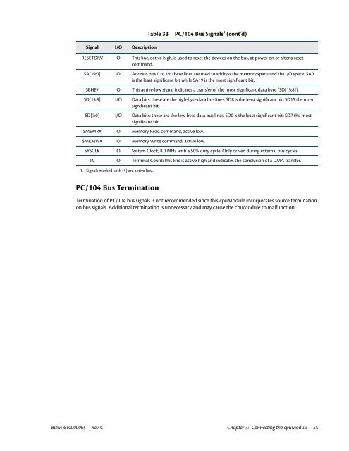
Table 33<br />
PC/104 Bus Signals 1 (cont’d)<br />
Signal I/O Description<br />
RESETDRV O This line, active high, is used to reset the devices on the bus, at power-on or after a reset<br />
command.<br />
SA[19:0] O Address bits 0 to 19: these lines are used to address the memory space and the I/O space. SA0<br />
is the least significant bit while SA19 is the most significant bit.<br />
SBHE# O This active-low signal indicates a transfer of the most significant data byte (SD[15:8]).<br />
SD[15:8] I/O Data bits: these are the high-byte data bus lines. SD8 is the least significant bit; SD15 the most<br />
significant bit.<br />
SD[7:0] I/O Data bits: these are the low-byte data bus lines. SD0 is the least significant bit; SD7 the most<br />
significant bit.<br />
SMEMR# O Memory Read command, active low.<br />
SMEMW# O Memory Write command, active low.<br />
SYSCLK O System Clock, 8.0 MHz with a 50% duty cycle. Only driven during external bus cycles.<br />
TC O Terminal Count: this line is active high and indicates the conclusion of a DMA transfer.<br />
1. Signals marked with (#) are active low.<br />
PC/104 Bus Termination<br />
Termination of PC/104 bus signals is not recommended since this cpuModule incorporates source termination<br />
on bus signals. Additional termination is unnecessary and may cause the cpuModule to malfunction.<br />
BDM-610000065 Rev C Chapter 3: Connecting the cpuModule 55


