

CME136686LX Hardware Manual - RTD Embedded Technologies ...
CME136686LX Hardware Manual - RTD Embedded Technologies ...
CME136686LX Hardware Manual - RTD Embedded Technologies ...

You also want an ePaper? Increase the reach of your titles
YUMPU automatically turns print PDFs into web optimized ePapers that Google loves.
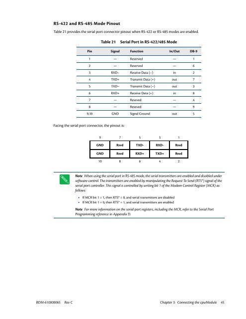
RS-422 and RS-485 Mode Pinout<br />
Table 21 provides the serial port connector pinout when RS-422 or RS-485 modes are enabled.<br />
Table 21<br />
Serial Port in RS-422/485 Mode<br />
Pin Signal Function In/Out DB-9<br />
1 — Reserved — 1<br />
2 — Reserved — 6<br />
3 RXD– Receive Data (–) in 2<br />
4 TXD+ Transmit Data (+) out 7<br />
5 TXD– Transmit Data (–) out 3<br />
6 RXD+ Receive Data (+) in 8<br />
7 — Reseved — 4<br />
8 — Reseved — 9<br />
9,10 GND Signal Ground out 5<br />
Facing the serial port connector, the pinout is:<br />
9 7 5 3 1<br />
GND Rsvd TXD- RXD- Rsvd<br />
GND Rsvd RXD+ TXD+ Rsvd<br />
10 8 6 4 2<br />
Note When using the serial port in RS-485 mode, the serial transmitters are enabled and disabled under<br />
software control. The transmitters are enabled by manipulating the Request To Send (RTS*) signal of the<br />
serial port controller. This signal is controlled by writing bit 1 of the Modem Control Register (MCR) as<br />
follows:<br />
• If MCR bit 1 = 1, then RTS* = 0, and serial transmitters are disabled<br />
• If MCR bit 1 = 0, then RTS* = 1, and serial transmitters are enabled<br />
Note For more information on the serial port registers, including the MCR, refer to the Serial Port<br />
Programming reference in Appendix D.<br />
BDM-610000065 Rev C Chapter 3: Connecting the cpuModule 45


