

CME136686LX Hardware Manual - RTD Embedded Technologies ...
CME136686LX Hardware Manual - RTD Embedded Technologies ...
CME136686LX Hardware Manual - RTD Embedded Technologies ...

Create successful ePaper yourself
Turn your PDF publications into a flip-book with our unique Google optimized e-Paper software.
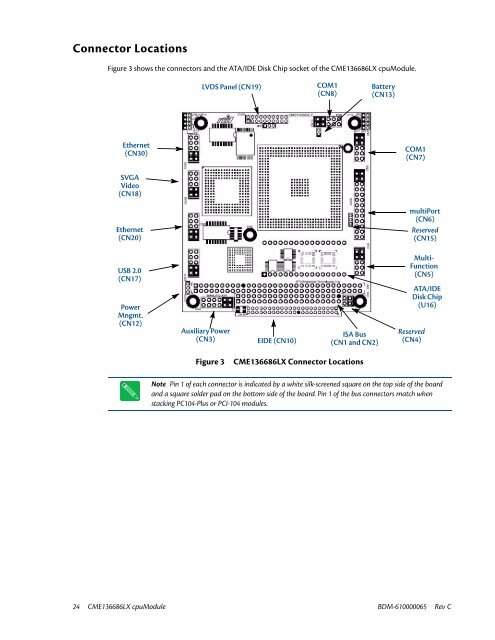
Connector Locations<br />
Figure 3 shows the connectors and the ATA/IDE Disk Chip socket of the <strong>CME136686LX</strong> cpuModule.<br />
LVDS Panel (CN19)<br />
COM1<br />
(CN8)<br />
Battery<br />
(CN13)<br />
Ethernet<br />
(CN30)<br />
COM1<br />
(CN7)<br />
SVGA<br />
Video<br />
(CN18)<br />
Ethernet<br />
(CN20)<br />
multiPort<br />
(CN6)<br />
Reserved<br />
(CN15)<br />
USB 2.0<br />
(CN17)<br />
Power<br />
Mngmt.<br />
(CN12)<br />
Auxiliary Power<br />
(CN3)<br />
EIDE (CN10)<br />
ISA Bus<br />
(CN1 and CN2)<br />
Multi-<br />
Function<br />
(CN5)<br />
ATA/IDE<br />
Disk Chip<br />
(U16)<br />
Reserved<br />
(CN4)<br />
Figure 3<br />
<strong>CME136686LX</strong> Connector Locations<br />
Note Pin 1 of each connector is indicated by a white silk-screened square on the top side of the board<br />
and a square solder pad on the bottom side of the board. Pin 1 of the bus connectors match when<br />
stacking PC104-Plus or PCI-104 modules.<br />
24 <strong>CME136686LX</strong> cpuModule BDM-610000065 Rev C


