

CME136686LX Hardware Manual - RTD Embedded Technologies ...
CME136686LX Hardware Manual - RTD Embedded Technologies ...
CME136686LX Hardware Manual - RTD Embedded Technologies ...

Create successful ePaper yourself
Turn your PDF publications into a flip-book with our unique Google optimized e-Paper software.
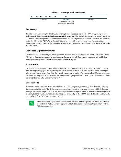
Table 47<br />
Interrupt Mask Enable 454h<br />
D7 D6 D5 D4 D3 D2 D1 D0<br />
Reserved<br />
Int Mask<br />
1 = Interrupt is masked<br />
0=Interrupt is enabled<br />
Reserved<br />
Interrupts<br />
In order to use an interrupt with aDIO, the interrupt must first be selected in the BIOS setup utility under<br />
Advanced, I/O Devices, aDIO Configuration, aDIO Interrupt. The Digital I/O can use interrupts 3, 5, 6, 7, 10,<br />
11, and 12. The interrupt must also be reserved so that is it not assigned to PCI devices. To reserve the interrupt,<br />
enter the BIOS under PCIPnP and change the interrupt you wish to use to “Reserved.” Then, select the<br />
appropriate interrupt mode in the DIO Control register. Also, verify that the Int Mask bit is cleared in the Wake<br />
Control register<br />
Advanced Digital Interrupts<br />
There are three Advanced Digital Interrupt modes available. These three modes are Event, Match, and Strobe.<br />
The use of these three modes is to monitor state changes at the aDIO connector. Interrupts are enabled by<br />
writing to the Digital IRQ Mode field in the DIO-Control register.<br />
Event Mode<br />
When this mode is enabled, Port 0 is latched into the DIO-Compare register at 8.33 MHz. The aDIO circuitry<br />
includes deglitching logic. The deglitching requires pulses on Port 0 to be at least 240 ns in width. As long as<br />
changes are present longer than that, the event is guaranteed to register. Pulses as small as 120 ns can register as<br />
an event, but they must occur between the rising and falling edge of the 8.33 MHz clock. To enter Event mode,<br />
set bits [4:3] of the DIO-Control register to “10”.<br />
Match Mode<br />
When this mode is enabled, Port 0 is latched into the DIO-Compare register at 8.33 MHz. The aDIO circuitry<br />
includes deglitching logic. The deglitching requires pulses on Port 0 to be at least 120 ns in width. As long as<br />
changes are present longer than that, the match is guaranteed to register. Pulses as small as 60 ns can register as<br />
a match, but they must occur between the rising and falling edge of the 8.33 MHz clock. To enter Match mode,<br />
set bits [4:3] of the DIO-Control register to “11”.<br />
Note Make sure bits [4:3] are set BEFORE writing the DIO-Compare register. If you do not set them first,<br />
the contents of the DIO-Compare register could be lost because the Event mode latches in Port 0 into the<br />
DIO-Compare register.<br />
BDM-610000065 Rev C Chapter 4: Using the cpuModule 69


