

CME136686LX Hardware Manual - RTD Embedded Technologies ...
CME136686LX Hardware Manual - RTD Embedded Technologies ...
CME136686LX Hardware Manual - RTD Embedded Technologies ...

You also want an ePaper? Increase the reach of your titles
YUMPU automatically turns print PDFs into web optimized ePapers that Google loves.
External Power Management (CN12)<br />
An external power management connector (CN12) is available for external devices to wake the system from low<br />
power states. Some low power modes require that +5 V standby power is applied to the cpuModule during the<br />
wake event.<br />
For more information on power management, including a description of the board’s supported wake options,<br />
refer to the Power Management section on page 79.<br />
Table 34 External Power Management (CN12)<br />
Pin Signal Function<br />
1 +5V_STDBY +5 V standby Power<br />
2 GND Ground<br />
2 PME# Power Management Event input<br />
Optional RTC Battery Input (CN13)<br />
The optional RTC battery input is the connection for an external backup battery. This battery is used by the<br />
cpuModule when system power is removed in order to preserve the date and time in the real time clock.<br />
Connecting a battery is only required to maintain time when power is completely removed from the cpuModule.<br />
A battery is not required for board operation.<br />
Table 35 Optional RTC Battery Input (CN13)<br />
Pin Signal Function<br />
1 BAT RTC Battery Input<br />
2 GND Ground<br />
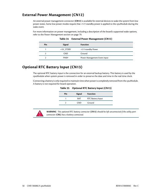
WARNING This optional RTC battery connector (CN13) should be left unconnected if the utility port<br />
connector (CN5) has a battery connected.<br />
56 <strong>CME136686LX</strong> cpuModule BDM-610000065 Rev C


