7800 Controller - User Manual - Scott Safety
7800 Controller - User Manual - Scott Safety
7800 Controller - User Manual - Scott Safety

Create successful ePaper yourself
Turn your PDF publications into a flip-book with our unique Google optimized e-Paper software.
Model <strong>7800</strong> <strong>User</strong>s <strong>Manual</strong><br />
Revision E<br />
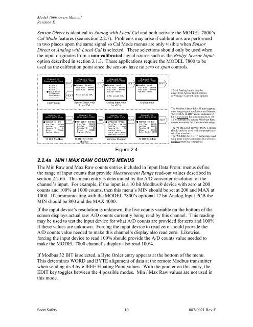
Sensor Direct is identical to Analog with Local Cal and both activate the MODEL <strong>7800</strong>’s<br />
Cal Mode features (see section 2.2.7). Problems may arise if calibrations are performed<br />
in two places upon the same signal so Cal Mode menus are only visible when Sensor<br />
Direct or Analog with Local Cal is selected. These selections should only be used when<br />
the input originates from a non-calibrated signal source such as the Bridge Sensor Input<br />
option described in section 3.1.3. These applications require the MODEL <strong>7800</strong> to be<br />
used as the calibration point since the sensors have no zero or span controls.<br />
Figure 2.4<br />
2.2.4a MIN / MAX RAW COUNTS MENUS<br />
The Min Raw and Max Raw counts entries included in Input Data From: menus define<br />
the range of input counts that provide Measurement Range read-out values described in<br />
section 2.2.6b. This menu entry is determined by the A/D converter resolution of the<br />
channel’s input. For example, if the input is a 10 bit Modbus® device with zero at 200<br />
counts and 100% at 1000 counts, then this menu’s MIN should be set at 200 and MAX at<br />
1000. If communicating with the MODEL <strong>7800</strong>’s optional 12 bit Analog Input PCB the<br />
MIN should be 800 and the MAX 4000.<br />
If the input device’s resolution is unknown, the live counts variable on the bottom of the<br />
screen displays actual raw A/D counts currently being read by this channel. This reading<br />
may be used to test the input device for what A/D counts are provided for zero and 100%<br />
if these values are unknown. Forcing the input device to read zero should provide the<br />
A/D counts value needed to make this channel’s display also read zero. Likewise,<br />
forcing the input device to read 100% should provide the A/D counts value needed to<br />
make the MODEL <strong>7800</strong> channel’s display also read 100%.<br />
If Modbus 32 BIT is selected, a Byte Order entry appears at the bottom of the menu.<br />
This determines WORD and BYTE alignment of data at the remote Modbus transmitter<br />
when sending its 4 byte IEEE Floating Point values. With the pointer on this entry, the<br />
EDIT key toggles between the 4 possible modes. Min / Max Raw values are not used in<br />
this mode.<br />
<strong>Scott</strong> <strong>Safety</strong><br />
10<br />
087-0021 Rev F