7800 Controller - User Manual - Scott Safety
7800 Controller - User Manual - Scott Safety
7800 Controller - User Manual - Scott Safety

You also want an ePaper? Increase the reach of your titles
YUMPU automatically turns print PDFs into web optimized ePapers that Google loves.
Model <strong>7800</strong> <strong>User</strong>s <strong>Manual</strong><br />
Revision E<br />
Figure 3.9<br />
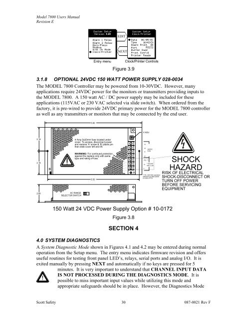
3.1.8 OPTIONAL 24VDC 150 WATT POWER SUPPLY 028-0034<br />
The MODEL <strong>7800</strong> <strong>Controller</strong> may be powered from 10-30VDC. However, many<br />
applications require 24VDC power for the monitors or transmitters providing inputs to<br />
the MODEL <strong>7800</strong>. A 150 watt AC / DC power supply may be included for these<br />
applications (115VAC or 230 VAC selected via slide switch). When ordered from the<br />
factory, it is pre-wired to provide 24VDC primary power for the MODEL <strong>7800</strong> controller<br />
as well as any transmitters or monitors that may be connected by the end user.<br />
Figure 3.8<br />
SECTION 4<br />
4.0 SYSTEM DIAGNOSTICS<br />
A System Diagnostic Mode shown in Figures 4.1 and 4.2 may be entered during normal<br />
operation from the Setup menu. The entry menu indicates firmware revision and offers<br />
useful routines for testing front panel LED’s, relays, serial ports and analog I/O. It is<br />
exited manually by pressing NEXT and automatically if no keys are pressed for 5<br />
minutes. It is very important to understand that CHANNEL INPUT DATA<br />
IS NOT PROCESSED DURING THE DIAGNOSTICS MODE. It is<br />
!<br />
possible to miss important input values while utilizing this mode and<br />
appropriate safeguards should be in place. However, the Diagnostics Mode<br />
<strong>Scott</strong> <strong>Safety</strong><br />
30<br />
087-0021 Rev F