DeNight Special 50 Manual - CMC Versand
DeNight Special 50 Manual - CMC Versand
DeNight Special 50 Manual - CMC Versand

Create successful ePaper yourself
Turn your PDF publications into a flip-book with our unique Google optimized e-Paper software.
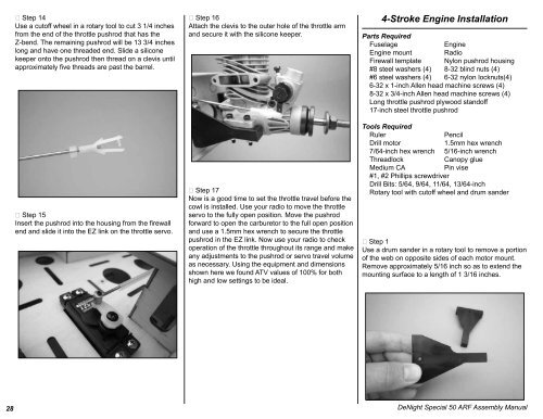
Step 14<br />
Use a cutoff wheel in a rotary tool to cut 3 1/4 inches<br />
from the end of the throttle pushrod that has the<br />
Z-bend. The remaining pushrod will be 13 3/4 inches<br />
long and have one threaded end. Slide a silicone<br />
keeper onto the pushrod then thread on a clevis until<br />
approximately five threads are past the barrel.<br />
Step 15<br />
Insert the pushrod into the housing from the firewall<br />
end and slide it into the EZ link on the throttle servo.<br />
Step 16<br />
Attach the clevis to the outer hole of the throttle arm<br />
and secure it with the silicone keeper.<br />
Step 17<br />
Now is a good time to set the throttle travel before the<br />
cowl is installed. Use your radio to move the throttle<br />
servo to the fully open position. Move the pushrod<br />
forward to open the carburetor to the full open position<br />
and use a 1.5mm hex wrench to secure the throttle<br />
pushrod in the EZ link. Now use your radio to check<br />
operation of the throttle throughout its range and make<br />
any adjustments to the pushrod or servo travel volume<br />
as necessary. Using the equipment and dimensions<br />
shown here we found ATV values of 100% for both<br />
high and low settings to be ideal.<br />
4-Stroke Engine Installation<br />
Parts Required<br />
Fuselage<br />
Engine<br />
Engine mount Radio<br />
Firewall template Nylon pushrod housing<br />
#8 steel washers (4) 8-32 blind nuts (4)<br />
#6 steel washers (4) 6-32 nylon locknuts(4)<br />
6-32 x 1-inch Allen head machine screws (4)<br />
8-32 x 3/4-inch Allen head machine screws (4)<br />
Long throttle pushrod plywood standoff<br />
17-inch steel throttle pushrod<br />
Tools Required<br />
Ruler<br />
Pencil<br />
Drill motor<br />
1.5mm hex wrench<br />
7/64-inch hex wrench 5/16-inch wrench<br />
Threadlock<br />
Canopy glue<br />
Medium CA<br />
Pin vise<br />
#1, #2 Phillips screwdriver<br />
Drill Bits: 5/64, 9/64, 11/64, 13/64-inch<br />
Rotary tool with cutoff wheel and drum sander<br />
Step 1<br />
Use a drum sander in a rotary tool to remove a portion<br />
of the web on opposite sides of each motor mount.<br />
Remove approximately 5/16 inch so as to extend the<br />
mounting surface to a length of 1 3/16 inches.<br />
28 <strong>DeNight</strong> <strong>Special</strong> <strong>50</strong> ARF Assembly <strong>Manual</strong>

![P01(Oxalys EP) [更新済み].ai - Kyosho](https://img.yumpu.com/26948574/1/184x260/p01oxalys-ep-ai-kyosho.jpg?quality=85)