July-August - Air Defense Artillery School
July-August - Air Defense Artillery School
July-August - Air Defense Artillery School

You also want an ePaper? Increase the reach of your titles
YUMPU automatically turns print PDFs into web optimized ePapers that Google loves.
40<br />
Where ex: 0 is 800 mils. Lm is % (206), or 154 mils.<br />
(Actually 161.)<br />
The foreg~ing treatment of angular travel leads should<br />
be of interest to all officers dealing with the subject. Howeyer,<br />
from the standpoint of practical application, the principles<br />
here developed may be summarized as follows:<br />
For machine guns developing muzzle \'elocities of 2600-<br />
2800 ft./sec. and for all target courses having midpoint<br />
ranges (Omln) up to 1200 yards .<br />
THE COAST ARTILLERY ]OllRJ\'AL<br />
(l) The angular trm'el lead (Lm) in mils at the midpoint<br />
is 14 mils for each 20 mi.jhr. target speed;<br />
that is, 70, 140. and 210 mils respectively for<br />
speeds of 100, 200, and 300 miles per hour. It<br />
should be of interest to note that these values are<br />
likewise correct for "lateral" lead as required on<br />
Central Tracer Control equipment, since target<br />
travel at the midpoint is seen as horizontal. Although<br />
this similarity to lateral lead occurs only at<br />
the midpoint, it may provide a valuable check in<br />
using sight equipment where lateral and vertical<br />
leads must be set separately. (For guns having<br />
shorter times of Hight than the Cal. .50 a similar<br />
constant may be determined, varying directly according<br />
to the time of Hight for 1000 yards; for instance,<br />
the constant for the 40mm gun is 13 mils for each<br />
20 mi.,lhr., and the midpoint lead for 200 mi.jhr, is<br />
130 mils.)<br />
(2) The angular travel lead (L.n) for an approaching<br />
target is % of the midpoint lead when the angle of<br />
approach is 45 degrees (800 mils), and ~ of the<br />
midpoint lead when the angle of approach is thirty<br />
degrees (533 mils). These rules are sufficiently accurate<br />
for practical use.<br />
0) Leads for targets on the receding leg of a course are<br />
not generally considered important. However, a<br />
receding angle of approach of 45 degrees requires<br />
about % of the midpoint lead, and a receding angle<br />
of approach of thirty degrees requires about % of<br />
the midpoint lead.<br />
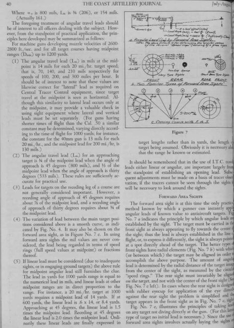
( -+) The variation of lead between the main target positions<br />
considered above is a smooth curve, as indicated<br />
by Fig. No.4. It may also be shown on the<br />
forward area sight, as in Figure No. 7 c. In using<br />
forward area sights the mil values are never considered,<br />
the lead being regarded in terms of speed<br />
rings (full speed values at midpoint) or fractions<br />
thereof.<br />
(5) If linear lead must be considered (due to inadequate<br />
sights, or in engaging ground targets) the above rule<br />
for midpoint angular lead still furnishes the clue.<br />
The lead in yards for 1000 yards range is equal to<br />
the numerical lead in mils, and linear leads at other<br />
midpoint ranges are in direct proportion to the<br />
range. For instance, a 20 mi.jhr. target at 1000<br />
yards requires a midpoint lead of 14 yards. If at<br />
600 yards, the linear lead is .6 x 14, or 8.4 yards.<br />
Approaching at 45 degrees, the linear lead is 1.5<br />
times the midpoint lead. Receding at 45 degrees<br />
the linear lead is 2.0 times the midpoint lead. Ordinarily<br />
these linear leads are finally expressed in<br />
1~._ .~~~::7<br />
. ,- -~- m~;fJS: 0<br />
~<br />
•• ~-.<br />
~. T.<br />
PI.;If~ ~C,,' klL.<br />
lI!I> ...y 7)--,.. .. ~/.s ~ 6oz. ~, .. ~,<br />
'-RONT R€.AR ~ E8.S2!:a.<br />
j, Twn ,&0,,";/10,. e~0/ ro'-JNI::7,.o! 4~ S;.i'h~.s.1<br />
(2) 0 @ 0 @F/,M<br />
(i""<br />
C. cross/nQ CourJe W//h FA .5:<br />
~<br />
Figure 7<br />
target lengths rather than in yards, the length<br />
target being assumed. Obviously it is necessaryal<br />
that the range be known or estimated.<br />
It should be remembered that in the use of I.T.C. tra\,<br />
leads either linear or angular, are important largely fr<br />
the standpoint of establishing an opening lead. Subst<br />
quent adjustments must be made on a basis of tracer obser<br />
vation; if the tracers cannot be seen through the sights<br />
will be necessary to look around the sights.<br />
FORWARD AREA SIGHTS<br />
The forward area sight is at this time the only practi<br />
method known by which a gunner can instantly appl<br />
angular leads of known value to antiaircraft targets. Fi<br />
No. 7 a indicates the principle by which angular leads a<br />
established by the sight. The target must be carried in t<br />
front sight as always appearing to Hy towards the center<br />
the sight; thus the lead is always established in the line 0<br />
Hight, or, to express it differently, the sight is always point<br />
at a spot directly ahead of the target. The better types<br />
front sights have radial elements (Fig. No.7 b) with whic<br />
(or between which) the target may be aligned in order t<br />
accomplish the above purpose. The amount of angul<br />
lead is determined by the radial distance of the target ima<br />
from the center of the sight, as measured by the circu<br />
"speed rings." The rear sight must invariably be alig<br />
011 the target, and not with the center of the front sight.(~<br />
Fig. No.7 c left). In cases where the rear sight is deSign<br />
with rubber eyecup for application of the eye direct!<br />
against the rear sight the problem is simplified and. ~<br />
target appears in the front sight as in Fig. No. 7 c, ng ht<br />
Fig. No. 7 c, illustrates the principles of taking I<br />
on any target not diving directly at the gun. (For this lat<br />
type of target no initial lead is necessary.) Since the use<br />
forward area sights involves actually laying the sightS