July-August - Air Defense Artillery School
July-August - Air Defense Artillery School
July-August - Air Defense Artillery School

Create successful ePaper yourself
Turn your PDF publications into a flip-book with our unique Google optimized e-Paper software.
Improvised Depression Position<br />
By Captain David J. Caldwell, Coast <strong>Artillery</strong> Corps<br />
EDITOR'S NOTE: Tile method of obtaillillg apprCY.I:imate<br />
range as describ~ ill tile folloll'illg article lIatHrally illl'olres<br />
certaill assllmptiolls. Ullder some atmospheric mid<br />
tide cOllditiollS, large errors ma)' be expect~.<br />
The method herein described may be used as an emergency<br />
range finding system to serve when the normal range<br />
finding equipment of a battery is not being manned, or may<br />
be used as an expedient when other range finding equipment<br />
is not available. Frequent use may be made of this<br />
device in equipping observation posts with a simple yet<br />
dependable range finder, thus enhancing the value of intelligence<br />
reported. The system is not adapted to stations<br />
of low elevation, 150 feet above sea level being the practical<br />
minimum. Tests bv the writer over a six months<br />
period at a number of different installations, varying in<br />
height from 220 feet to 850 feet, have proven its accuracy.<br />
Use is made of either a 1910 Al or an M1918 azimuth<br />
instrument. The 1910 A 1 instrument, being of heavier<br />
construction and more stable, is preferable. The azimuth<br />
instrument must have a very stable mounting so that it<br />
will continuously remain level and be free from vibration.<br />
Its height above sea level must be accurately determined.<br />
The operation in brief is as follows: The instrument is<br />
focused on the target and the target water-lined with the<br />
horizontal cross wire. (The 1910 Al instrument has no<br />
horizontal cross wire; however, the tops of the horizontal<br />
scale graduations may be used as such). Care being taken<br />
not to change the depression angle at which the target was<br />
water-lined, the instrument is refocused on a previously<br />
calibrated range pole located in the vicinity of instrument,<br />
turning the instrument in azimuth if necessary, and the<br />
range to the target read on the scale of the range pole with<br />
the horizontal cross wire as an index.<br />
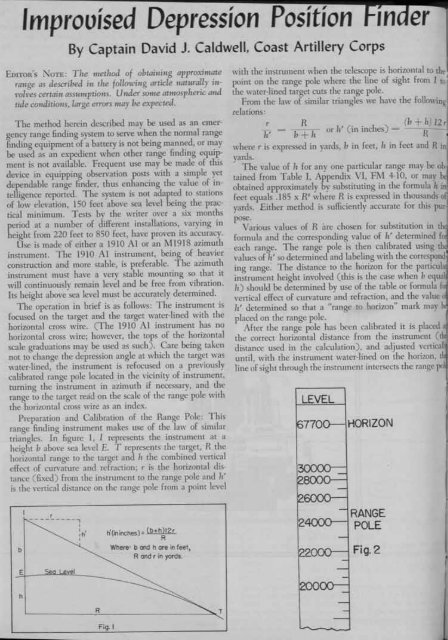
Preparation and Calibration of the Range Pole: This<br />
range finding instrument makes use of the law of similar<br />
triangles. In figure 1, I represents the instrument at a<br />
height b above sea level E. T represents the target, R the<br />
horizontal range to the target and h the combined vertical<br />
effect of curvature and refraction; r is the horizontal distance<br />
(fixed) from the instrument to the range pole and h'<br />
is the vertical distance on the range pole from a point level<br />
b<br />
E<br />
h<br />
r<br />
---------...,<br />
eveI<br />
I<br />
:h' I<br />
R<br />
Fig. I<br />
n(in inches) = ( b+h )12 r<br />
R<br />
Where: b and h are in feel,<br />
Rand r in yards.<br />
T<br />
LEVEL<br />
HORIZON<br />
RANGE<br />
POLE<br />
Fig.2<br />
er<br />
with the instrument when the telescope is horizontal to the<br />
point on the range pole where the line of sight from I toj<br />
the water-lined target cuts the range pole.<br />
From the law of similar triangles we have the following<br />
relations:<br />
r R , .. (b + 11I 12 r<br />
h' b + h or h (m mches) = R •<br />
where r is expressed in yards, b in feet, II in feet and R in<br />
yards.<br />
. The value of h for anyone particular range may be OIr<br />
tained from Table I, Appendix VI, Fi\l 4-10, or may be<br />
obtained approximately by substituting in the formula II inI<br />
feet equals .185 x R2 where R is expressed in thousands of]<br />
yards.<br />
pose.<br />
Either method is sufficiently accurate for this pur-<br />
Various values<br />
formula and the<br />
of R iue chosen for substitution in th~<br />
corresponding value of h' determined 1'0<br />
each range. The range pole is then calibrated using th<br />
values of h' so determined and labeling with the correspond.<br />
ing range. The distance to the horizon for the particula<br />
instrument height involved (this is the case when b equal<br />
h) should be determined by use of the table or formula f<br />
vertical effect of curvature and refraction, and the value 0<br />
h' determined so that a "range to horizon" mark may<br />
placed on the range pole.<br />
After the range pole has been calibrated it is placed a<br />
the correct horizontal distance from the instrument (t<br />
distance used in the calculation), and adjusted vcrticall<br />
until, with the instrument water-lined on the horizon. t<br />
line of sight through the instrument intersects the range po<br />
200