July-August - Air Defense Artillery School
July-August - Air Defense Artillery School
July-August - Air Defense Artillery School

You also want an ePaper? Increase the reach of your titles
YUMPU automatically turns print PDFs into web optimized ePapers that Google loves.
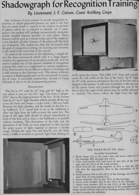
Shadowgraph for Recognition T rainingl<br />
By Lieutenant J. F. Carson, Coast <strong>Artillery</strong> Corps<br />
One \\"eakness of most systems of aircraft recognition instmction<br />
in which projected pictures are used is the fact<br />
that too much detail is exposed to the student in pictures<br />
of planes which he is required to identify. As a consequence,<br />
the student will, perhaps unconsciously, memorize<br />
certain detailed features peculiar to each plane. These<br />
features will be used as a crutch at first and if the tendencv<br />
is not checked, all other features of the plane will slip back<br />
out of memorv. The student has then lost all contact with<br />
the goal of re~ognition training; the learning and retention<br />
in the mind of the total fonn of the aircraft.<br />
To assist in the correction of this deficiency, a simple device<br />
has been constmcted which will, to a large degree,<br />
simulate the appearance of an aeroplane in the sky. It is not<br />
used to replace any of the present methods of recognition<br />
training but rather as a supplement to current equipment.<br />
It has been found to be an effective adjunct to learning and<br />
it adds interest to the classroom work. This device is known<br />
to most as a Shadowgraph and can be constructed in a number<br />
of ways. A successful constmction, devised at Camp<br />
Edwards, is shown in the accompanying picture.<br />
DESCRIPTION<br />
The box is 18" wide by 24" long and 16" high at the<br />
rear where it rests on two 6~" legs. The front is deeper,<br />
22W', due to the sloping bottom of the box. At the bottom<br />
front is a 6" by 6" light chamber which extends all the way<br />
across the front and houses a socket with a 200-watt bulb.<br />
Between the light chamber and the inside of the box is a<br />
tin bulkhead. A 2" round hole is cut in the bulkhead to<br />
allow the light from the bulb to enter the main box. The<br />
bulge of the light bulb should be placed immediately in<br />
front of this hole and as close to the bulkhead as is possible<br />
without touching. The dimensions of the hole and the<br />
placement of the bulb are most important as they provide<br />
the point source of light required to prevent a double<br />
image. \Vithin the main box and directly over the bulkhead,<br />
a balle is installed to prevent light from shining di-<br />
rectly upon the screen. This balle is 6" deep and extends<br />
across the full width of the box at the front. An 8" high<br />
bv 10" wide mirror is centered in the rear of the box and is<br />
hinged at the bottom. A stiff wire is attached to the top rear<br />
of the mirror frame and projects through the rear of the<br />
box so that the angle of the mirror mav be readily adjusted<br />
as required. The mirror reRects the light from the light<br />
THE FOCKE-WULF FW 190A3<br />
Assemb[y Instructions<br />
1. Bend wings (A) at the center line and insert sideways in<br />
the fuselage (B) through slot (A 1).<br />
2. Take cross-section (C) and insert in slot (C) of the fuse-<br />
[age and slot (C2) of the wing section.<br />
3. Bend forward the wing supports of (C) so that the tabs<br />
sl~p into the appropriate slots at the extremities of the<br />
wmgs.<br />
4. Insert section (0) in slot (Dl) of the fuselage and through<br />
s[ot( 02) of cross-section (C).<br />
5. Insert tai[plane (E) in slot (El) of the fuselage.<br />
6. Insert cross member (F) in slot (F 1) of the fuselage.<br />
7. Insert cross member (G) in slot (G 1) of the fuselage.<br />
Note: In certain front and rear aspects of the assembled rno dd<br />
better results will be achieved by bending section (0) upwards<br />
so that it touches the tail plane.