Controller - Institute of Transportation Engineers
Controller - Institute of Transportation Engineers
Controller - Institute of Transportation Engineers

You also want an ePaper? Increase the reach of your titles
YUMPU automatically turns print PDFs into web optimized ePapers that Google loves.
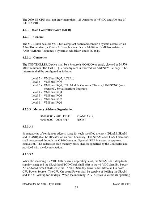
The 2070-1B CPU shall not draw more than 1.25 Amperes <strong>of</strong> +5VDC and 500 mA <strong>of</strong><br />
ISO+12 VDC.<br />
4.2.3 Main <strong>Controller</strong> Board (MCB)<br />
4.2.3.1 General<br />
The MCB shall be a 3U VME bus compliant board and contain a system controller, an<br />
A24-D16 interface, a Master & Slave bus interface, a Multilevel VMEbus Arbiter, a<br />
FAIR VMEbus Requester, a system clock driver, and BTO (64).<br />
4.2.3.2 <strong>Controller</strong><br />
The CONTROLLER Device shall be a Motorola MC68360 or equal, clocked at 24.576<br />
MHz minimum. The Fast IRQ Service System is reserved for AGENCY use only. The<br />
Interrupts shall be configured as follows:<br />
Level 7 - VMEbus IRQ7, ACFAIL<br />
Level 6 - VMEbus IRQ6<br />
Level 5 - VMEbus IRQ5, CPU Module Counters / Timers, LINESYNC (auto<br />
vectored), Serial Interface Interrupts<br />
Level 4 - VMEbus IRQ4<br />
Level 3 - VMEbus IRQ3<br />
Level 2 - VMEbus IRQ2<br />
Level 1 - VMEbus IRQ1<br />
4.2.3.3 Memory Address Organization<br />
4.2.3.3.1<br />
8000 0000 - 80FF FFFF STANDARD<br />
9000 0000 - 9000 FFFF SHORT<br />
16 megabytes <strong>of</strong> contiguous address space for each specified memory (DRAM, SRAM<br />
and FLASH) shall be allocated on an even boundary. The SRAM and FLASH memories<br />
shall be accessed through the OS-9 Operating System's RBF Manager, or approved<br />
equivalent. The address <strong>of</strong> each memory block shall be specified by the Contractor and<br />
provided with the documentation.<br />
4.2.3.3.2<br />
When the incoming +5 VDC falls below its operating level, the SRAM shall drop to its<br />
standby state; and the SRAM and TOD Clock shall shift to the +5 VDC Standby Power.<br />
An on-board circuit shall sense the +5 VDC Standby Power and shift to an On-board<br />
CPU Power Source. The CPU On-board Power shall be capable <strong>of</strong> holding the SRAM<br />
and TOD Clock up for 30 days. When the incoming +5 VDC rises to within its operating<br />
Standard for the ATC – Type 2070 March 29, 2001<br />
29