

INSTALLATION INSTRUCTIONS - Lennox
INSTALLATION INSTRUCTIONS - Lennox
INSTALLATION INSTRUCTIONS - Lennox

You also want an ePaper? Increase the reach of your titles
YUMPU automatically turns print PDFs into web optimized ePapers that Google loves.
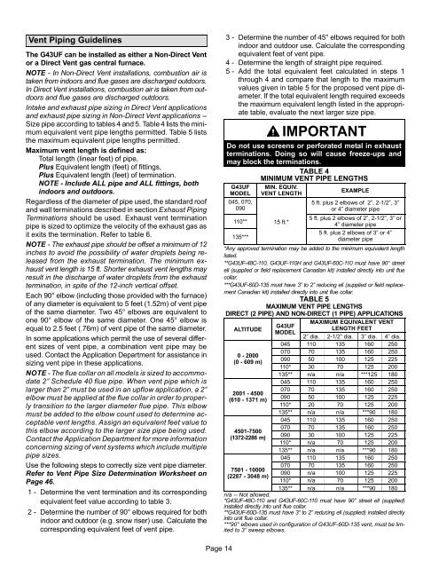
Vent Piping Guidelines<br />
The G43UF can be installed as either a Non−Direct Vent<br />
or a Direct Vent gas central furnace.<br />
NOTE − In Non-Direct Vent installations, combustion air is<br />
taken from indoors and flue gases are discharged outdoors.<br />
In Direct Vent installations, combustion air is taken from outdoors<br />
and flue gases are discharged outdoors.<br />
Intake and exhaust pipe sizing in Direct Vent applications<br />
and exhaust pipe sizing in Non-Direct Vent applications −−<br />
Size pipe according to tables 4 and 5. Table 4 lists the minimum<br />
equivalent vent pipe lengths permitted. Table 5 lists<br />
the maximum equivalent pipe lengths permitted.<br />
Maximum vent length is defined as:<br />
Total length (linear feet) of pipe,<br />
Plus Equivalent length (feet) of fittings,<br />
Plus Equivalent length (feet) of termination.<br />
NOTE − Include ALL pipe and ALL fittings, both<br />
indoors and outdoors.<br />
Regardless of the diameter of pipe used, the standard roof<br />
and wall terminations described in section Exhaust Piping<br />
Terminations should be used. Exhaust vent termination<br />
pipe is sized to optimize the velocity of the exhaust gas as<br />
it exits the termination. Refer to table 6.<br />
NOTE − The exhaust pipe should be offset a minimum of 12<br />
inches to avoid the possibility of water droplets being released<br />
from the exhaust termination. The minimum exhaust<br />
vent length is 15 ft. Shorter exhaust vent lengths may<br />
result in the discharge of water droplets from the exhaust<br />
termination, in spite of the 12−inch vertical offset.<br />
Each 90° elbow (including those provided with the furnace)<br />
of any diameter is equivalent to 5 feet (1.52m) of vent pipe<br />
of the same diameter. Two 45° elbows are equivalent to<br />
one 90° elbow of the same diameter. One 45° elbow is<br />
equal to 2.5 feet (.76m) of vent pipe of the same diameter.<br />
In some applications which permit the use of several different<br />
sizes of vent pipe, a combination vent pipe may be<br />
used. Contact the Application Department for assistance in<br />
sizing vent pipe in these applications.<br />
NOTE − The flue collar on all models is sized to accommodate<br />
2" Schedule 40 flue pipe. When vent pipe which is<br />
larger than 2" must be used in an upflow application, a 2"<br />
elbow must be applied at the flue collar in order to properly<br />
transition to the larger diameter flue pipe. This elbow<br />
must be added to the elbow count used to determine acceptable<br />
vent lengths. Assign an equivalent feet value to<br />
this elbow according to the larger size pipe being used.<br />
Contact the Application Department for more information<br />
concerning sizing of vent systems which include multiple<br />
pipe sizes.<br />
Use the following steps to correctly size vent pipe diameter.<br />
Refer to Vent Pipe Size Determination Worksheet on<br />
Page 46.<br />
1 − Determine the vent termination and its corresponding<br />
equivalent feet value according to table 3.<br />
2 − Determine the number of 90° elbows required for both<br />
indoor and outdoor (e.g. snow riser) use. Calculate the<br />
corresponding equivalent feet of vent pipe.<br />
3 − Determine the number of 45° elbows required for both<br />
indoor and outdoor use. Calculate the corresponding<br />
equivalent feet of vent pipe.<br />
4 − Determine the length of straight pipe required.<br />
5 − Add the total equivalent feet calculated in steps 1<br />
through 4 and compare that length to the maximum<br />
values given in table 5 for the proposed vent pipe diameter.<br />
If the total equivalent length required exceeds<br />
the maximum equivalent length listed in the appropriate<br />
table, evaluate the next larger size pipe.<br />
IMPORTANT<br />
Do not use screens or perforated metal in exhaust<br />
terminations. Doing so will cause freeze−ups and<br />
may block the terminations.<br />
TABLE 4<br />
MINIMUM VENT PIPE LENGTHS<br />
G43UF<br />
MODEL<br />
045, 070,<br />
090<br />
110**<br />
135***<br />
MIN. EQUIV.<br />
VENT LENGTH<br />
15 ft.*<br />
EXAMPLE<br />
5 ft. plus 2 elbows of 2", 2−1/2", 3"<br />
or 4" diameter pipe<br />
5 ft. plus 2 elbows of 2", 2−1/2", 3" or<br />
4" diameter pipe<br />
5 ft. plus 2 elbows of 3" or 4"<br />
diameter pipe<br />
*Any approved termination may be added to the minimum equivalent length<br />
listed.<br />
**G43UF−48C−110, G43UF−110H and G43UF−60C−110 must have 90° street<br />
ell (supplied or field replacement Canadian kit) installed directly into unit flue<br />
collar.<br />
***G43UF−60D−135 must have 3" to 2" reducing ell (supplied or field replacement<br />
Canadian kit) installed directly into unit flue collar.<br />
TABLE 5<br />
MAXIMUM VENT PIPE LENGTHS<br />
DIRECT (2 PIPE) AND NON−DIRECT (1 PIPE) APPLICATIONS<br />
ALTITUDE<br />
0 − 2000<br />
(0 − 609 m)<br />
2001 − 4500<br />
(610 − 1371 m)<br />
4501−7500<br />
(1372−2286 m)<br />
7501 − 10000<br />
(2287 − 3048 m)<br />
G43UF<br />
MODEL<br />
MAXIMUM EQUIVALENT VENT<br />
LENGTH FEET<br />
2" dia. 2−1/2" dia. 3" dia. 4" dia.<br />
045 110 135 160 250<br />
070 70 135 160 250<br />
090 50 100 125 225<br />
110* 30 70 125 200<br />
135** n/a n/a ***125 180<br />
045 110 135 160 250<br />
070 70 135 160 250<br />
090 50 100 125 225<br />
110* 20 70 125 200<br />
135** n/a n/a ***90 180<br />
045 110 135 160 250<br />
070 70 135 160 250<br />
090 30 100 125 225<br />
110* n/a 70 125 200<br />
135** n/a n/a ***90 180<br />
045 110 135 160 250<br />
070 70 135 160 250<br />
090 n/a 100 125 225<br />
110* n/a 70 125 200<br />
135** n/a n/a ***90 180<br />
n/a −− Not allowed.<br />
*G43UF−48C−110 and G43UF−60C−110 must have 90° street ell (supplied)<br />
installed directly into unit flue collar.<br />
**G43UF−60D−135 must have 3" to 2" reducing ell (supplied) installed directly<br />
into unit flue collar.<br />
***90° elbows used in configuration of G43UF−60D−135 vent, must be limited<br />
to 3" sweep elbows.<br />
Page 14


