

INSTALLATION INSTRUCTIONS - Lennox
INSTALLATION INSTRUCTIONS - Lennox
INSTALLATION INSTRUCTIONS - Lennox

Create successful ePaper yourself
Turn your PDF publications into a flip-book with our unique Google optimized e-Paper software.
Other Unit Adjustments<br />
Primary Limit<br />
The primary limit is located on the heating compartment<br />
vestibule panel. This limit is factory set and requires no adjustment.<br />
Flame Rollout Switches (Two)<br />
These manually reset switches are located on the burner<br />
box. If tripped, check for adequate combustion air before<br />
resetting.<br />
Pressure Switch<br />
The pressure switch is located in the heating compartment<br />
on the combustion air inducer. This switch checks for proper<br />
combustion air inducer operation before allowing ignition<br />
trial. The switch is factory−set and requires no adjustment.<br />
Temperature Rise<br />
After the furnace has been started and supply and return air<br />
temperatures have been allowed to stabilize, check the<br />
temperature rise. If necessary, adjust the blower speed to<br />
maintain the temperature rise within the range shown on<br />
the unit nameplate. Increase the blower speed to decrease<br />
the temperature. Decrease the blower speed to increase<br />
the temperature rise. Failure to adjust the temperature rise<br />
may cause erratic limit operation.<br />
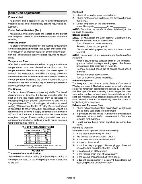
Fan Control<br />
The fan on time of 45 seconds is not adjustable. The fan off<br />
delay(amount of time that the blower operates after the<br />
heat demand has been satisfied) may be adjusted by<br />
changing the jumper position across the five pins on the<br />
integrated control. The unit is shipped with a factory fan off<br />
setting of 90 seconds. The fan off delay affects comfort and<br />
is adjustable to satisfy individual applications. Adjust the<br />
fan off delay to achieve a supply air temperature between<br />
90° and 110°F at the exact moment that the blower is de−<br />
energized. Longer off delay settings provide lower return<br />
air temperatures; shorter settings provide higher return air<br />
temperatures. See figure 45.<br />
FAN-OFF TIME ADJUSTMENT<br />
To adjust fan−off timing, reposition jumper across pins to<br />
achieve desired setting.<br />
FIGURE 45<br />
Thermostat Heat Anticipation<br />
Set the heat anticipator setting (if adjustable) according to<br />
the amp draw listed on the wiring diagram that is attached<br />
to the unit.<br />
Electrical<br />
1 − Check all wiring for loose connections.<br />
2 − Check for the correct voltage at the furnace (furnace<br />
operating).<br />
3 − Check amp-draw on the blower motor.<br />
Motor Nameplate__________Actual__________<br />
NOTE − Do not secure the electrical conduit directly to the<br />
air ducts or structure.<br />
Blower Speeds<br />
NOTE − CFM readings are taken external to unit with a dry<br />
evaporator coil and without accessories.<br />
Turn off electrical power to furnace.<br />
Remove blower access panel.<br />
Disconnect existing speed tap at control board speed<br />
terminal.<br />
NOTE − Termination of any unused motor leads must be<br />
insulated.<br />
Refer to blower speed selection chart on unit wiring diagram<br />
for desired heating or cooling speed. See Blower<br />
performance data beginning on Page 37.<br />
Connect selected speed tap at control board speed<br />
terminal.<br />
Resecure blower access panel.<br />
Turn on electrical power to furnace.<br />
Electronic Ignition<br />
The integrated control has an added feature of an internal<br />
Watchguard control. The feature serves as an automatic reset<br />
device for ignition control lockout caused by ignition failure.<br />
This type of lockout is usually due to low gas line pressure.<br />
After one hour of continuous thermostat demand for<br />
heat, the Watchguard will break and remake thermostat demand<br />
to the furnace and automatically reset the control to<br />
begin the ignition sequence.<br />
Exhaust and Air Intake Pipe<br />
1 − Check exhaust and air intake connections for tightness<br />
and to make sure there is no blockage.<br />
2 − Is pressure switch closed? Obstructed exhaust pipe<br />
will cause unit to shut off at pressure switch. Check termination<br />
for blockages.<br />
3 − Reset manual flame rollout switches on burner box<br />
cover.<br />
Failure To Operate<br />
If the unit fails to operate, check the following:<br />
1 − Is the thermostat calling for heat?<br />
2 − Are access panels securely in place?<br />
3 − Is the main disconnect switch closed?<br />
4 − Is there a blown fuse?<br />
5 − Is the filter dirty or plugged? Dirty or plugged filters will<br />
cause the limit control to shut the unit off.<br />
6 − Is gas turned on at the meter?<br />
7 − Is the manual main shut-off valve open?<br />
8 − Is the internal manual shut-off valve open?<br />
9 − Is the unit ignition system in lock out? If the unit locks out<br />
again, inspect the unit for blockages.<br />
Page 36


