

INSTALLATION INSTRUCTIONS - Lennox
INSTALLATION INSTRUCTIONS - Lennox
INSTALLATION INSTRUCTIONS - Lennox

Create successful ePaper yourself
Turn your PDF publications into a flip-book with our unique Google optimized e-Paper software.
Electrical<br />
ELECTROSTATIC DISCHARGE (ESD)<br />
Precautions and Procedures<br />
CAUTION<br />
Electrostatic discharge can affect electronic components.<br />
Take precautions during furnace installation<br />
and service to protect the furnace’s electronic<br />
controls. Precautions will help to avoid control exposure<br />
to electrostatic discharge by putting the furnace,<br />
the control and the technician at the same<br />
electrostatic potential. Neutralize electrostatic<br />
charge by touching hand and all tools on an unpainted<br />
unit surface, such as the gas valve or blower<br />
deck, before performing any service procedure.<br />
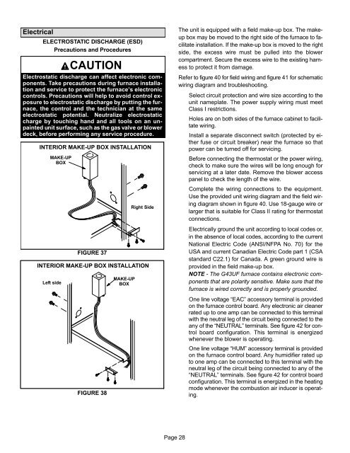
INTERIOR MAKE−UP BOX <strong>INSTALLATION</strong><br />
MAKE−UP<br />
BOX<br />
FIGURE 37<br />
Right Side<br />
INTERIOR MAKE−UP BOX <strong>INSTALLATION</strong><br />
Left side<br />
FIGURE 38<br />
MAKE−UP<br />
BOX<br />
The unit is equipped with a field make−up box. The make−<br />
up box may be moved to the right side of the furnace to facilitate<br />
installation. If the make−up box is moved to the right<br />
side, the excess wire must be pulled into the blower<br />
compartment. Secure the excess wire to the existing harness<br />
to protect it from damage.<br />
Refer to figure 40 for field wiring and figure 41 for schematic<br />
wiring diagram and troubleshooting.<br />
Select circuit protection and wire size according to the<br />
unit nameplate. The power supply wiring must meet<br />
Class I restrictions.<br />
Holes are on both sides of the furnace cabinet to facilitate<br />
wiring.<br />
Install a separate disconnect switch (protected by either<br />
fuse or circuit breaker) near the furnace so that<br />
power can be turned off for servicing.<br />
Before connecting the thermostat or the power wiring,<br />
check to make sure the wires will be long enough for<br />
servicing at a later date. Remove the blower access<br />
panel to check the length of the wire.<br />
Complete the wiring connections to the equipment.<br />
Use the provided unit wiring diagram and the field wiring<br />
diagram shown in figure 40. Use 18−gauge wire or<br />
larger that is suitable for Class II rating for thermostat<br />
connections.<br />
Electrically ground the unit according to local codes or,<br />
in the absence of local codes, according to the current<br />
National Electric Code (ANSI/NFPA No. 70) for the<br />
USA and current Canadian Electric Code part 1 (CSA<br />
standard C22.1) for Canada. A green ground wire is<br />
provided in the field make−up box.<br />
NOTE − The G43UF furnace contains electronic components<br />
that are polarity sensitive. Make sure that the<br />
furnace is wired correctly and is properly grounded.<br />
One line voltage EAC" accessory terminal is provided<br />
on the furnace control board. Any electronic air cleaner<br />
rated up to one amp can be connected to this terminal<br />
with the neutral leg of the circuit being connected to the<br />
any of the NEUTRAL" terminals. See figure 42 for control<br />
board configuration. This terminal is energized<br />
whenever the blower is operating.<br />
One line voltage HUM" accessory terminal is provided<br />
on the furnace control board. Any humidifier rated up<br />
to one amp can be connected to this terminal with the<br />
neutral leg of the circuit being connected to any of the<br />
NEUTRAL" terminals. See figure 42 for control board<br />
configuration. This terminal is energized in the heating<br />
mode whenever the combustion air inducer is operating.<br />
Page 28


