Versamark DS5600 Series - Kodak
Versamark DS5600 Series - Kodak
Versamark DS5600 Series - Kodak

Create successful ePaper yourself
Turn your PDF publications into a flip-book with our unique Google optimized e-Paper software.
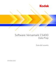
<strong>Versamark</strong> <strong>DS5600</strong> <strong>Series</strong><br />
Printing Systems<br />
Operator Guide<br />
0114332-603
FCC Compliance Statement<br />
This equipment has been tested and found to comply with the limits for a Class A digital device, pursuant to Part 15 of the FCC Rules. These<br />
limits are designed to provide reasonable protection against harmful interference when the equipment is operated in a commercial environment.<br />
This equipment generates, uses, and can radiate radio frequency energy and, if not installed and used in accordance with the instruction manual,<br />
may cause harmful interference to radio communications. Operation of this equipment in a residential area is likely to cause harmful interference,<br />
in which case the user will be required to correct the interference at his own expense.<br />
Note: Good quality, shielded (braided shielded) cables must be used for the RS-232-C and Centronics interfaces.<br />
Canadian EMI Compliance Statement<br />
Le présent appareil numérique n’émet pas de bruits radioélectriques dépassant les limites applicables aux appareils numériques de la classe A<br />
prescrites dans le Règlement sur le brouillage radioélectrique édicté par le ministère des Communications du Canada.<br />
This digital apparatus does not exceed the Class A limits for radio noise emissions from digital apparatus set out in the Radio Interference Regulations<br />
of the Canadian Department of Communications.<br />
EMI-CISPR 22/EN 55 022/CE Marking<br />
Warning: This is a Class A product. In a domestic environment, this product may cause radio interference in which case the user may be<br />
required to take adequate measures.<br />
<strong>Versamark</strong> <strong>DS5600</strong> <strong>Series</strong> Printing Systems Operator Guide<br />
Part Number Media Revision Date Description ECN<br />
0114332-603 PDF 02 09/2010 Revision for CS150 Version 4.0.2.0 K10566<br />
Previous Releases<br />
Part Number Media Revision Date Description ECN<br />
0114332-602<br />
0114332-603<br />
Print<br />
PDF<br />
001 01/2008 Initial release with CS150 and CS150 UTS K7790<br />
© <strong>Kodak</strong>, 2010. All rights reserved.<br />
This document contains proprietary information of Eastman <strong>Kodak</strong> Company or its licensors and is their exclusive property. It may not be<br />
reproduced without a written agreement from Eastman <strong>Kodak</strong> Company. No patent or other license is granted to this information.<br />
The software described in this document is furnished under a license agreement. The software may not be used or copied except as provided in<br />
the license agreement.<br />
Eastman <strong>Kodak</strong> Company makes no warranty of any kind with regard to the contents of this document, including, but not limited to, the implied<br />
warranties of merchantability and fitness for a particular purpose. Eastman <strong>Kodak</strong> Company shall not be liable for any errors or for<br />
compensatory, incidental or consequential damages in connection with the furnishing, performance, or use of this document or the examples<br />
contained herein. Information concerning products not manufactured by Eastman <strong>Kodak</strong> Company. is provided without warranty or<br />
representation of any kind, and Eastman <strong>Kodak</strong> Company will not be liable for any damages resulting from the use of such information.<br />
<strong>Kodak</strong> and <strong>Versamark</strong> are trademarks of Eastman <strong>Kodak</strong> Company.<br />
0114332-603 09/2010
Scope<br />
This guide describes how to operate the <strong>Kodak</strong> <strong>Versamark</strong> <strong>DS5600</strong> <strong>Series</strong><br />
Printing Systems. These printing systems produce letter-quality, variable<br />
data images using continuous inkjet technology at up to 500 fpm<br />
(150 mpm) with print resolutions of 240x240, 240x480, 300x300, or<br />
300x600 dots per inch (dpi).<br />
The <strong>DS5600</strong> series printing systems can be used for business forms, tag<br />
and label, direct mail, booklets, bar coding, numbering, addressing,<br />
personalization, and billing statements with or without spot color. These<br />
printing systems are modular and can be configured for web or sheet-fed<br />
presses, collators, mail bases, folders, and a variety of other inline and<br />
offline finishing equipment.<br />
For <strong>DS5600</strong> operation, the following system requirements apply to the<br />
system components:<br />
• <strong>Kodak</strong> <strong>Versamark</strong> CS150 System Controller Software Dashboard<br />
Version 4.0.1.0 or higher<br />
• Microsoft Windows XP Professional with Service Pack 2.0<br />
• Ethernet-compatible narrow-format printers (with Compact DS Main<br />
board installed)<br />
• Ethernet-compatible wide-format print stations (with Compact DS<br />
Main board installed)<br />
• Fluid Controller Software Release 5.000 or higher<br />
For additional information about the components used in the <strong>DS5600</strong><br />
series printing systems, see the following publications:<br />
• <strong>Kodak</strong> <strong>Versamark</strong> CS150 System Controller Software Getting Started<br />
Guide<br />
• <strong>Kodak</strong> <strong>Versamark</strong> DP5222 and DP5340 Printing Systems Operator’s<br />
Guide<br />
The procedures in this guide should be performed only by an operator<br />
who has received on-site training from <strong>Kodak</strong>.<br />
Operator Guide 3
Scope<br />
Text Notations<br />
This manual uses the following typographical conventions.<br />
This style<br />
Ready<br />
go<br />
ENTER<br />
[NEXT]<br />
Save<br />
File Open<br />
ALT+F1<br />
ALT, TAB<br />
xx,yy<br />
jobfile.dat<br />
Refers to<br />
Text displayed by the software.<br />
Anything you type, exactly as it appears, whether referenced<br />
in text or at a prompt.<br />
Special keys on the keyboard, such as enter, alt, and<br />
spacebar.<br />
Buttons and lights on the printer operator panel.<br />
Software command buttons and sections of dialog boxes,<br />
such as group boxes, text boxes, and text fields.<br />
A menu and a specific menu command.<br />
Pressing more than one key at the same time.<br />
Pressing more than one key in sequence.<br />
Variable in error messages and text.<br />
File names.<br />
Safety Notations<br />
The following definitions indicate safety precautions to the operator.<br />
Note: Information that needs to be brought to the reader’s attention.<br />
Caution: A situation where a mistake could result in the destruction of data or<br />
system-type damage.<br />
! WARNING<br />
A potential hazard that could result in serious injury or death.<br />
! DANGER<br />
An imminent hazard that will result in serious injury or death.<br />
Service and Support<br />
Technical equipment support is available 24 hours a day, 7 days a week.<br />
Software and applications support is available 8:00 a.m. to 5:00 p.m.<br />
EST/EDT, Monday through Friday.<br />
Call for telephone or on-site technical support; to order parts or supplies;<br />
to request documentation or product information.<br />
U.S.A., Canada, and<br />
worldwide<br />
Phone<br />
+1-800-472-4839<br />
+1-937-259-3739<br />
Fax<br />
+1-937-259-3808<br />
Europe +41-22-354-1400 +41-22-354-1480<br />
Asia/Pacific Rim +65 6744 6400 +65 6744 6700<br />
Japan +81-3-5621-2220 +81-3-5621-2221<br />
4 <strong>DS5600</strong> <strong>Series</strong> Printing Systems
Contents<br />
Chapter 1. Overview<br />
<strong>DS5600</strong> Configurations........................................................................................11<br />
<strong>DS5600</strong> Components ..........................................................................................13<br />
System Controller..........................................................................................13<br />
Print Stations.................................................................................................14<br />
Printheads .....................................................................................................15<br />
Fluid Containers ............................................................................................15<br />
System Operation ................................................................................................16<br />
Chapter 2. Operation<br />
System Preparation .............................................................................................18<br />
Startup Procedures..............................................................................................19<br />
System Connections .....................................................................................19<br />
Startup Sequence .........................................................................................20<br />
Controller Operation ............................................................................................21<br />
Menus and Screens ......................................................................................22<br />
Device Configuration.....................................................................................24<br />
Database Configuration ................................................................................25<br />
Job Selection.................................................................................................26<br />
Job Printing ...................................................................................................27<br />
Using Online Help .........................................................................................30<br />
Print Station Operation ........................................................................................31<br />
Keyboard Controls ........................................................................................31<br />
Screen Displays ............................................................................................32<br />
Menu Screens........................................................................................ 32<br />
Status Screens ...................................................................................... 33<br />
Control Menu Procedures .............................................................................35<br />
Service Menu Procedures.............................................................................37<br />
Parameters Menu Procedures ......................................................................38<br />
Pressure Adjustment ............................................................................. 39<br />
Vacuum Adjustment............................................................................... 39<br />
Stim Adjustment..................................................................................... 40<br />
Stim Phase Adjustment ......................................................................... 40<br />
Charge Voltage Adjustment................................................................... 40<br />
Standby.................................................................................................. 41<br />
Setup Menu Procedures ...............................................................................41<br />
Chapter 3. Messages<br />
Message Displays................................................................................................44<br />
Message List........................................................................................................44<br />
Chapter 4. Operator Maintenance<br />
Daily Maintenance ...............................................................................................47<br />
Printhead Bottom Cover Cleaning.................................................................47<br />
Printhead Cleaning........................................................................................47<br />
Weekly Maintenance ...........................................................................................48<br />
Printhead Air Filter ........................................................................................48<br />
Cabinet Air Filter ...........................................................................................48<br />
Operator Guide 5
Figures<br />
Figure 1.1 <strong>DS5600</strong> printing system configuration...........................................12<br />
Figure 1.2 <strong>DS5600</strong> components, single DT3 system......................................13<br />
Figure 1.3 DT3 Print Station ...........................................................................14<br />
Figure 1.4 Typical ink-jet printing system........................................................16<br />
Figure 2.1 Connections, CS150 controller on DT3 cabinet.............................19<br />
Figure 2.2 Network hub and power connections, DT3 print station ................20<br />
Figure 2.3 Main screen, CS150 software........................................................21<br />
Figure 2.4 Diagnostics window .......................................................................22<br />
Figure 2.5 Devices menu, Diagnostics screen................................................22<br />
Figure 2.6 Select service setup window, CS150 software ..............................24<br />
Figure 2.7 Print job selection window .............................................................26<br />
Figure 2.8 Database window ..........................................................................26<br />
Figure 2.9 Configuring New Fields..................................................................27<br />
Figure 2.10 Production window - after set up, CS150 ......................................27<br />
Figure 2.11 Run window, CS150 ......................................................................29<br />
Figure 2.12 Fluid controller software title screen ..............................................31<br />
Figure 2.13 Menu tree, DT3 print station software............................................32<br />
Figure 2.14 Status screen layout ......................................................................33<br />
Figure 2.15 Printhead Ready status screen......................................................33<br />
Figure 2.16 Control Menu, DT3 print station software ......................................35<br />
Figure 2.17 Parameters Adjustments screen, Control Menu ............................35<br />
Figure 2.18 Remote/Service Selection screen, Control Menu ..........................35<br />
Figure 2.19 Service Menu, DT3 print station software......................................37<br />
Figure 2.20 Parameters Menu, DT3 print station software ...............................38<br />
Figure 2.21 Setup Menu, DT3 print station software ........................................41<br />
Figure 3.1 Print station operator terminal screen display................................43<br />
Figure 3.2 Display screen with sample messages..........................................43<br />
Figure 3.3 Error message during startup ........................................................44<br />
Figure 4.1 Printhead air filter, DH6240 ...........................................................48<br />
Figure 4.2 Cabinet filter, DT3 print station .....................................................48<br />
Operator Guide 7
Tables<br />
Table 1.1 Printhead performance ..............................................................15<br />
Table 2.1 System status display summary ................................................34<br />
Table 2.2 Control menu functions..............................................................36<br />
Table 2.3 Service menu function ...............................................................37<br />
Operator Guide 9
Chapter 1.<br />
Overview<br />
This overview describes <strong>Kodak</strong> <strong>Versamark</strong> <strong>DS5600</strong> <strong>Series</strong> Printing<br />
Systems in the following sections:<br />
• <strong>DS5600</strong> Configurations<br />
• <strong>DS5600</strong> Components<br />
Configuration descriptions describe the various combinations of<br />
components that can make up a system.<br />
Component descriptions identify the controller, printers, and print stations<br />
used in the <strong>DS5600</strong>, and the system nomenclature.<br />
<strong>DS5600</strong> Configurations<br />
The <strong>DS5600</strong> series supports up to four printers and print stations in the<br />
following combinations:<br />
• <strong>Kodak</strong> <strong>Versamark</strong> CS150 System Controller with two <strong>Kodak</strong><br />
<strong>Versamark</strong> DP5600 <strong>Series</strong> Print Stations<br />
• <strong>Kodak</strong> <strong>Versamark</strong> CS150 System Controller with one narrow-format<br />
printer (<strong>Kodak</strong> <strong>Versamark</strong> DP5222 Printer or <strong>Kodak</strong> <strong>Versamark</strong><br />
DP5340 Printer) and two <strong>Kodak</strong> <strong>Versamark</strong> DP5600 <strong>Series</strong> Print<br />
Stations<br />
• <strong>Kodak</strong> <strong>Versamark</strong> CS150 System Controller with two narrow-format<br />
printers (<strong>Kodak</strong> <strong>Versamark</strong> DP5222 Printer or <strong>Kodak</strong> <strong>Versamark</strong><br />
DP5340 Printer) and two <strong>Kodak</strong> <strong>Versamark</strong> DP5600 <strong>Series</strong> Print<br />
Stations<br />
• <strong>Kodak</strong> <strong>Versamark</strong> CS150 System Controller with three narrow-format<br />
printers (<strong>Kodak</strong> <strong>Versamark</strong> DP5222 Printer or <strong>Kodak</strong> <strong>Versamark</strong><br />
DP5340 Printer) and one <strong>Kodak</strong> <strong>Versamark</strong> DP5600 <strong>Series</strong> Print<br />
Station<br />
The narrow-format printers support the following printheads:<br />
• <strong>Kodak</strong> <strong>Versamark</strong> DH5222 Printheads, which has a 2.13" (5.41 cm)<br />
print array and prints resolutions of 120x120 or 120x240 dpi<br />
• <strong>Kodak</strong> <strong>Versamark</strong> DH5340 Printheads, which has a 1.07" (2.71 cm)<br />
print array and prints resolutions of 240x240 or 240x480 dpi<br />
The DP5600 series print station can support any of the following<br />
printheads:<br />
• <strong>Kodak</strong> <strong>Versamark</strong> DH5300 Printhead, which has a 2.77" (7.04 cm)<br />
print array and prints resolutions of 300x300 or 300x600<br />
• <strong>Kodak</strong> <strong>Versamark</strong> DH6300 Printhead, which has a 3.41" (8.66 cm)<br />
print array and prints resolutions of 300x300 or 300x600<br />
• <strong>Kodak</strong> <strong>Versamark</strong> DH6240 Printhead, which has a 4.27" (10.85 cm)<br />
print array and prints resolutions of 240x240 or 240x480<br />
Operator Guide 11
Chapter 1. Overview<br />
<strong>DS5600</strong> Configurations<br />
Figure 1.1 shows the different <strong>DS5600</strong> series configurations.<br />
Figure 1.1<br />
<strong>DS5600</strong> printing system configuration<br />
Second, third and fourth printers<br />
CS150 on DS5000<br />
DP5222<br />
or<br />
DP5340<br />
2.13" DH5222<br />
or<br />
1.07" DH5340<br />
CS150 on <strong>DS5600</strong><br />
or<br />
DP5630<br />
DP5640<br />
or<br />
DP5650<br />
2.77" DH5300<br />
3.41" DH6300<br />
or<br />
4.27" DH6240<br />
Second DP5600 series print station<br />
Other system components such as the paper transport, cue sensor, tach<br />
encoder, finishing equipment, and printhead mount(s) are dependent on<br />
the specific combination installed.<br />
The <strong>DS5600</strong> series printing systems are identified as:<br />
• <strong>Kodak</strong> <strong>Versamark</strong> DP5630 Printing System<br />
Narrow-format printers and one or two DP5600 series print stations<br />
with DH5300 Printheads<br />
• <strong>Kodak</strong> <strong>Versamark</strong> DP5640 Printing System<br />
Narrow-format printers and one or two DP5600 series print stations<br />
with DH6240 Printheads<br />
• <strong>Kodak</strong> <strong>Versamark</strong> DP5650 Printing System<br />
Narrow-format printers and one or two DP5600 series print stations<br />
with DH6300 Printheads<br />
All configurations are compatible with the current model of the 38.5"<br />
non-stitch printhead mount.<br />
The specific installation and application requirements determine the other<br />
system components required. This guide provides operating instructions<br />
for a system with either narrow-format or wide-format printheads.<br />
Note: The term DH6240 is used for the 4.27" printhead in some system<br />
configurations, but that term is not used in this guide.<br />
12 <strong>DS5600</strong> <strong>Series</strong> Printing Systems
Chapter 1. Overview<br />
<strong>DS5600</strong> Components<br />
<strong>DS5600</strong> Components<br />
The <strong>DS5600</strong> series has the following standard components:<br />
• <strong>Kodak</strong> <strong>Versamark</strong> CS150 System Controller<br />
• Network hub<br />
• One printer or print station<br />
• Printhead<br />
• Umbilical<br />
• Fluid containers<br />
The system can include the following additional components:<br />
• System enclosure (same used for the <strong>Kodak</strong> <strong>Versamark</strong> DS5000<br />
<strong>Series</strong> Printing Systems)<br />
• Computer mounting shelf (used only on a <strong>Kodak</strong> <strong>Versamark</strong> DT3 Print<br />
Station)<br />
• Second, third, or fourth narrow-format printer<br />
• Second DT3 print station.<br />
Each printer or print station supports one printhead. Each printhead prints<br />
one color. Spot color printing is supported using multiple printheads.<br />
Printheads cannot be stitched.<br />
System Controller<br />
When the system does not include a DP5000 series printer (also called a<br />
narrow-format printer), the CS150 is mounted on a DT3 print station.<br />
Figure 1.2 shows the system components of a system that does not have<br />
a narrow-format printer.<br />
Figure 1.2<br />
<strong>DS5600</strong> components, single DT3 system<br />
Monitor<br />
Network hub<br />
Printhead<br />
PC shelf<br />
CS150 System Controller<br />
Umbilical<br />
DT3 print station cabinet<br />
Operator Guide 13
Chapter 1. Overview<br />
<strong>DS5600</strong> Components<br />
Print Stations<br />
The <strong>Kodak</strong> <strong>Versamark</strong> DP5600 Print Station is a new component used<br />
only in the <strong>DS5600</strong> <strong>Series</strong> Printing Systems.<br />
The DP5600 consists of a fluid controller for the printhead (DH5300,<br />
DH6240, or DH6300) and an operator terminal for the print station<br />
controller software. When the CS150 is mounted on a <strong>Kodak</strong> <strong>Versamark</strong><br />
DT2 cabinet, the same computer serves as the operator terminal for both<br />
the CS150 and the print station using a KVM (keyboard/video/monitor)<br />
switch.<br />
The DT3 cabinet (Figure 1.3) contains the entire fluid system for the<br />
printhead, an internal fluid controller PC, and the Compact DS Main<br />
Board with associated cables. The PC in the DT2 cabinet controls fluidic<br />
and electronic operation of the print station and umbilical. The Compact<br />
DS Main Board relays processes data received over the Ethernet from the<br />
CS150 and transmits rasterized, fiberoptic image data to the printhead.<br />
Figure 1.3<br />
DT3 Print Station<br />
Monitor<br />
Printhead<br />
Keyboard<br />
Fluid cabinet<br />
Data Main Board<br />
Umbilical<br />
14 <strong>DS5600</strong> <strong>Series</strong> Printing Systems
Chapter 1. Overview<br />
<strong>DS5600</strong> Components<br />
Printheads<br />
The printheads used in the <strong>DS5600</strong> series have the performance<br />
characteristics listed in Table 1.1.<br />
Table 1.1<br />
Model<br />
Printhead performance<br />
Print width Resolution (dpi)<br />
Nominal Exact X axis Y axis<br />
DH5340 1 inch 1.06 inch<br />
(2.69 cm)<br />
DH5222 2 inch 2.13 inch<br />
(5.41 cm)<br />
240<br />
240<br />
120<br />
120<br />
DH5300 4 inch 2.77 inch 300<br />
300<br />
DH6300 4 inch 3.41 inch<br />
(8.66cm)<br />
DH6240 4 inch 4.27 inch<br />
(10.85cm)<br />
x<br />
x<br />
x<br />
x<br />
x<br />
x<br />
240<br />
480<br />
120<br />
240<br />
300<br />
600<br />
Speed<br />
(fpm)<br />
500<br />
500<br />
500<br />
300 x 600 500<br />
240 x 240 500<br />
Resolution is measured in dots-per-inch (dpi) along the print array for the<br />
X axis and in the direction of substrate movement for the Y axis.<br />
Maximum speed in feet-per-minute (fpm) was determined printing a 4-line<br />
address with a 1-line Postnet barcode separated by 0.5-inch. Data<br />
prepared in IJPDS format can be printed faster, but the actual speed at<br />
which a given job can be printed is determined by the interaction of the<br />
image data and the inter-document spacing. Simulated imaging can be<br />
used to test the speed at which a job can be run.<br />
For <strong>DS5600</strong> operation, apply the following guidelines to printhead<br />
mounting:<br />
• Maximum height = 6 ft (183 cm) above the base of the printer cabinet.<br />
• Minimum height = 2 ft (61 cm) below the base.<br />
• For narrow-format printheads, the print array should be no more than<br />
0.5 inch (1.27 cm) above the transport belt. Optimum print quality is<br />
obtained with a printhead height of 0.125 inch (0.317 cm).<br />
• For the DH5300 and DH6300 (wide format) printheads, the maximum<br />
height is 0.1 inch above the transport belt.<br />
• For the DH6240 printhead, the maximum height is 0.125 inch above<br />
the transport belt.<br />
Fluid Containers<br />
The system requires external fluid containers for ink and replenisher fluid.<br />
These containers can be any combination of the following types:<br />
• 5.2 gallon (20 L) cubitainer<br />
• 55 gallon (209 L) drum<br />
• 275 gallon (1045 L) tote<br />
Operator Guide 15
Chapter 1. Overview<br />
System Operation<br />
The print station software monitors the level of ink stored in the internal<br />
tank, which is automatically filled from the external supply as ink is used.<br />
Replacing the external supplies can occur without stopping a job. You<br />
must monitor the fluid supplies using the print station software and<br />
replace the external ink or replenisher container when alerted by a “check<br />
external fluid containers” message.<br />
System Operation<br />
The <strong>DS5600</strong> series printing system uses data in the Native Input<br />
Command Version 3 (NIC3) format for narrow-format printers (a system<br />
with only DH6240 printheads can use IJPDS format data). The controller<br />
processes job data and sends image data to the printers and print<br />
stations over an RJ-45 Ethernet connection (Figure 1.4). This connection<br />
uses a network hub mounted behind the CS150 computer.<br />
The CS150 uses setup commands embedded in the NIC3 data to<br />
automatically set job parameters. Alternatively, you can enter job setup<br />
instructions at the CS150 operator terminal.<br />
Figure 1.4<br />
Typical ink-jet printing system<br />
CS160<br />
Data<br />
source<br />
NIC3<br />
Controls and status<br />
Data<br />
station<br />
Bit-mapped<br />
data<br />
Fiberoptic<br />
Controls<br />
and status<br />
Print Station<br />
Umbilical<br />
Fluid<br />
cabinet<br />
Printhead<br />
The job parameters and setup at the CS150 are applied to the data to<br />
determine which part of the bit-mapped data goes to each printhead.<br />
Embedded setup allows jobs to be run without any image positioning at<br />
the controller, however, the CS150 software can be used to correct the<br />
setup or make changes to it if needed.<br />
In a <strong>DS5600</strong> system, narrow-format printers operate with the CS150 just<br />
like they do in a DS5000 series printing system. The presence of one or<br />
two DT3 print stations does not change that relationship. The DT3 print<br />
stations operate with the CS150 in the following manner:<br />
• The CS150 serves the function of a <strong>Kodak</strong> <strong>Versamark</strong> CS220 System<br />
Controller Software or <strong>Kodak</strong> <strong>Versamark</strong> CS400 System Controller<br />
Software in a wide-format printing system such as the DS6240.<br />
• The Compact DS Main Board in the DT3 functions as the <strong>Kodak</strong><br />
<strong>Versamark</strong> CD120 Data Station or <strong>Kodak</strong> <strong>Versamark</strong> CD130 Data<br />
Station in a wide-format printing system.<br />
• The DT3 print station software operates normally, monitoring all<br />
aspects of fluid controller operation.<br />
Operating procedures and controls are described in Chapter 2,<br />
“Operation.”<br />
16 <strong>DS5600</strong> <strong>Series</strong> Printing Systems
Chapter 2.<br />
Operation<br />
Operation of a <strong>Kodak</strong> <strong>Versamark</strong> <strong>DS5600</strong> <strong>Series</strong> Printing System consists<br />
of the following procedures:<br />
• System Preparation<br />
• Startup Procedures<br />
• Controller Operation<br />
• Print Station Operation<br />
The <strong>Kodak</strong> <strong>Versamark</strong> CS150 System Controller Software is used to<br />
control the system. The CS150 can be used to control the fluid systems<br />
and data systems of narrow-format printers, but not <strong>Kodak</strong> <strong>Versamark</strong><br />
DP5600 <strong>Series</strong> Print Stations. When a DP5600 print station is configured,<br />
the Fluid Controller Software that runs on the computer in the DP5600<br />
print station must be used to control that fluid system and printhead.<br />
Note:<br />
If two DP5600 print stations are configured, each one must be operated<br />
using its own operator terminal. The first DP5600 shares the operator<br />
terminal of the CS150, but the second DP5600 has a separate operator<br />
terminal.<br />
The primary reference for all CS150 software procedures is the online<br />
Help (see “System Preparation”).<br />
Note:<br />
Systems ship with the current version of CS150 System Controller<br />
software (Version 4.0.2.0 as of publication of this guide). Systems with<br />
earlier versions of the software, including all versions called <strong>Kodak</strong> <strong>Versamark</strong><br />
Mailscape Software, may not be compatible with the <strong>DS5600</strong> series<br />
printing systems. Contact technical support for information on software<br />
upgrades.<br />
Operator Guide 17
Chapter 2. Operation<br />
System Preparation<br />
System Preparation<br />
Before the system can print, the following CS150 software procedures<br />
must be completed:<br />
• Set up production printers<br />
• Configure databases<br />
• Create print layouts<br />
All these procedures are described in the CS150 online Help. Access this<br />
information from any screen by selecting the Help button (shown below<br />
on the production “Dashboard” screen). Open specific Help topics by<br />
clicking on items in interactive lists or on the pull-down menus.<br />
Help button<br />
The final procedure in this sequence is production (see “Print Jobs”). All<br />
production printers must be configured as devices in the CS150 software,<br />
and each database to be used as a print source must be configured for<br />
printing.<br />
This configuration, which includes field and record definition as well as<br />
print layout, is saved in a configuration file (*. bcf).<br />
When the printers and databases are configured, a print job is started by<br />
selecting a printer and loading a configuration file (*. bcf).<br />
An optional CS150 module called Read and Image allows a CS150 user<br />
with a camera system (or barcode reader, magnetic strip reader, or optical<br />
character reader [OCR] and a production printing system) to personalize<br />
print products based on a customer number. For convenience, this Help<br />
refers to a camera system when discussing the Read and Image<br />
capability.<br />
18 <strong>DS5600</strong> <strong>Series</strong> Printing Systems
Chapter 2. Operation<br />
Startup Procedures<br />
The CS150 System Controller is primarily used with the <strong>Kodak</strong> <strong>Versamark</strong><br />
D-<strong>Series</strong> Printing Systems for applications that require bar coding,<br />
numbering, addressing, and personalizing. The CS150 can operate up to<br />
four printheads in various combinations (See “<strong>DS5600</strong> Configurations” on<br />
page 11). The feature key for the CS150 software must match the number<br />
and type of printheads being used.<br />
Startup Procedures<br />
Narrow-format printers should be powered-up normally before the<br />
controller is started. For a system a with DS5000 series enclosure, startup<br />
is done exactly the same as described in the <strong>Kodak</strong> <strong>Versamark</strong> CS150<br />
System Controller Software Getting Started Guide. Review the following<br />
procedures before starting the system initially:<br />
• System Connections<br />
• Startup Sequence<br />
System Connections<br />
For a system without a DS5000 series enclosure, check all the<br />
connections to the controller mounted under the shelf on the DT3 cabinet<br />
(Figure 2.1).<br />
Figure 2.1<br />
Connections, CS150 controller on DT3 cabinet<br />
Monitor power<br />
Data from controller<br />
Data out to printer<br />
Data from customer network<br />
PC power<br />
KVM for CS150<br />
CS150 software key<br />
KVM switch input<br />
KVM switch<br />
KVM for DT3<br />
Data output<br />
Operator Guide 19
Chapter 2. Operation<br />
Startup Procedures<br />
The <strong>DS5600</strong> series controller on the DT3 cabinet requires the following<br />
connections:<br />
Note:<br />
• Input power<br />
• Monitor<br />
• Keyboard<br />
• Mouse<br />
• Feature key (see note below)<br />
• Data source<br />
One input from the customer data source is required. The data source<br />
is typically a LAN or network drive.<br />
• Network hub data connections<br />
Each printer or print station must have an output cable from the<br />
24-port Ethernet switch installed in the system enclosure or the DT3<br />
shelf (Figure 1.2). Input to the hub is a connection to the system<br />
controller. Hub connections are done at installation and should not be<br />
changed unless a printer is added to the system or permanently<br />
removed. A connected printer does not have to be used. Only printers<br />
active in the current software configuration print.<br />
The CS150 software key (also called a “feature key”) is programmed for<br />
the number of printheads and optional software features of the system. If<br />
a feature is not active that is required, contact technical support.<br />
Startup Sequence<br />
Start the system using this sequence (Figure 2.1 and Figure 2.2):<br />
• Power up the print station(s)<br />
• Power up the narrow-format printer(s)<br />
• Power up the network hub<br />
• Power up the controller PC<br />
Figure 2.2<br />
Network hub and power connections, DT3 print station<br />
Up to four data outputs<br />
Single Data input from controller<br />
CS150 power<br />
DT3 cabinet power<br />
DT3 input power,<br />
PC and monitor power<br />
20 <strong>DS5600</strong> <strong>Series</strong> Printing Systems
Chapter 2. Operation<br />
Controller Operation<br />
Controller Operation<br />
When the controller powers up, the CS150 software main screen appears<br />
(Figure 2.3).<br />
Figure 2.3<br />
Main screen, CS150 software<br />
This section gives an overview of the software and five basic operating<br />
procedures:<br />
• Menus and Screens (overview)<br />
• Device Configuration<br />
• Database Configuration<br />
• Job Selection<br />
• Job Printing<br />
Operator Guide 21
Chapter 2. Operation<br />
Controller Operation<br />
Menus and Screens<br />
Operation of the system from the CS150 is done using selections under<br />
the following main menu buttons:<br />
The selections have the following functions:<br />
Production<br />
Used to select the files needed to print a job and do all other basic<br />
operating procedures.<br />
Configurator<br />
Used to configure a new printer or print station.<br />
Diagnostics<br />
Opens the Diagnostics window (Figure 2.4) that is used primarily for<br />
service procedures, but can be used to check the status of narrowformat<br />
printers fluid and data systems.<br />
Figure 2.4 Diagnostics window<br />
Note:<br />
The Diagnose selection on the main menu runs tests that check the<br />
status of all devices (printers and print stations) connected to the CS150.<br />
If a device is not communicating for any reason, it will show an error. A<br />
device that is powered off will not communicate. This screen is also used<br />
to remove a device from the setup (Figure 2.5). Consult a service technician<br />
before changing the system configuration or running diagnostics.<br />
Figure 2.5<br />
Devices menu, Diagnostics screen<br />
Exit<br />
Closes the CS150 software.<br />
About<br />
Provides the version number of the CS150 software.<br />
22 <strong>DS5600</strong> <strong>Series</strong> Printing Systems
Chapter 2. Operation<br />
Controller Operation<br />
Help<br />
Accesses online help. See “Using Online Help” on page 30.<br />
Clear messages<br />
Removes any active messages.<br />
NL<br />
US<br />
DE<br />
FR<br />
ES<br />
IT<br />
CZ<br />
ZH<br />
Changes the text to Dutch.<br />
Changes the text to English.<br />
Changes the text to German.<br />
Changes the text to French.<br />
Changes the text to Spanish.<br />
Changes the text to Italian.<br />
Changes the text to Czechoslavakian.<br />
Changes the text to traditional Chinese.<br />
Note:<br />
The correct optional components for the Microsoft Windows XP Professional<br />
operating system and the correct fonts must be installed on the<br />
controller PC for this function to work correctly.<br />
When the system is powered up, operation consists of the following<br />
procedures:<br />
• Device Configuration<br />
• Database Configuration<br />
• Job Selection<br />
• Job Printing<br />
• Using Online Help<br />
The 'Getting Started Tutorial’ explains these procedures in detail.<br />
Operator Guide 23
Chapter 2. Operation<br />
Controller Operation<br />
Device Configuration<br />
To print, each printer must be configured in the CS150 software. Use the<br />
following procedure to assign each printer to a service and configure that<br />
printer for use by the system:<br />
1. In the Dashboard window, select Diagnostics. The Diagnostics<br />
window appears.<br />
Unknown<br />
2. Select Services New Service (or press CTRL + INSERT) to create a<br />
service view for each printer or print station connected to the<br />
controller. An Unknown device icon appears (see example at left) and<br />
the Select Service dialog appears (Figure 2.6).<br />
Figure 2.6<br />
Select service setup window, CS150 software<br />
3. Select <strong>Kodak</strong> Service and click OK. The Service Dialog appears.<br />
4. Select the correct IP address for the device from the drop-down<br />
menu and then click OK.<br />
Note:<br />
The address selected must be set using DIP switches on the Compact DS<br />
Main Board in the printer or print station, and two devices cannot have the<br />
same address. If the address does not match the hardware setting, the<br />
warning “this device is not connected” appears when the device icon is<br />
selected. Contact your supervisor or a service technician if a device<br />
address needs to be changed. When the new device connects, select it<br />
by double-clicking the New Device icon in the list under Services. A<br />
dialog appears asking you to name the new device.<br />
24 <strong>DS5600</strong> <strong>Series</strong> Printing Systems
Chapter 2. Operation<br />
Controller Operation<br />
5. Enter an appropriate device name and click OK (the example screen<br />
below shows a DP5640 on port 192.168.200.32 named 5640-32).<br />
6. Repeat the configuration steps for each device in the system.<br />
7. Select File Export System Information (or press CTRL + S) and<br />
create a new system information file (*.bwi) or save the existing file.<br />
8. If adding a device changes any customer information, select Settings<br />
Customer Info and make the necessary changes.<br />
9. Exit Diagnostics.<br />
10. See the online Help for more information on job and printer setup.<br />
Database Configuration<br />
Use the following procedure to set up a print data source:<br />
1. In the Dashboard window, click the Configurator button. The<br />
Configurator window appears.<br />
2. Select File, then New to start the database wizard. Wizard pages 1<br />
through 4, Database selection, appear.<br />
3. From the scroll-able Database type list, select the version of DBASE<br />
that was used to create the database you will be configuring.<br />
4. Click Browse.<br />
5. In the open dialog, locate and select the DBASE file you want.<br />
6. Click the Open button.<br />
7. Back in wizard page 1 of 4, click Next. Wizard page 2 of 4, Table<br />
selection, appears.<br />
8. Select the desired database table form the table name drop-down list,<br />
then click Next. Wizard page 3 and 4, Layout config, appears.<br />
Operator Guide 25
Chapter 2. Operation<br />
Controller Operation<br />
9. You can view a database record by entering its relative number in the<br />
Current record number box. You can also specify the code page<br />
you want to be used for fields of type “string.” Finally, you may be able<br />
to select a database Index. When you are ready, click Next.<br />
10. You can use the Extra Fields window to define postal code fields to<br />
be used in your print layout. When you are finished defining postal<br />
codes (or if you do not want to define any postal codes), then click<br />
Next. Wizard page 4 of 4, Overview, appears. (Note: you can<br />
observe the results of the code page settings in the Overview page).<br />
11. In the Overview page, you can browse through the database<br />
contents. When you are ready, click Finish. The database you have<br />
just configured appears in the Database window, a secondary<br />
window of the Configurator window.<br />
12. Test the database either by selecting Edit and then Test database or<br />
by clicking the Toolbar button. For more information, see the graph in<br />
the online Help topic for data configuration.<br />
Job Selection<br />
Use the following procedure to specify which job is printed:<br />
1. Selecting Production allows you to go into the Configuration<br />
window and select a print job (Figure 2.7)<br />
Figure 2.7<br />
Print job selection window<br />
2. In the Production window, open the database you want to use<br />
(Figure 2.8).<br />
Figure 2.8<br />
Database window<br />
3. With a job and database selected, select a printer on the left side of<br />
the Production window (highlight and double click).<br />
26 <strong>DS5600</strong> <strong>Series</strong> Printing Systems
Chapter 2. Operation<br />
Controller Operation<br />
4. To create a new job setup, or change the setup to add necessary<br />
fields to the labels, drag the selected fields from the Field List and<br />
place them in the template (Figure 2.9).<br />
Figure 2.9<br />
Configuring New Fields<br />
5. When the setup is complete, the job is ready to run. Continue with<br />
“Job Printing.”<br />
Job Printing<br />
When the required files are ready, complete the following steps to print a<br />
job:<br />
1. In the Dashboard window, check the job and setup before starting to<br />
print (Figure 2.10). Also check the transport or mailbase to make sure<br />
it is ready to operate.<br />
Figure 2.10<br />
Production window - after set up, CS150<br />
Operator Guide 27
Chapter 2. Operation<br />
Controller Operation<br />
The Production window has the following buttons and field groups:<br />
Close<br />
Ends the current activity for running the print job and returns you to<br />
the Dashboard window.<br />
Run<br />
Starts printing a job. If necessary, any printers required are brought to<br />
ready before printing begins. When printing is ready, the Run window<br />
shows printing status in real time as the job runs.<br />
Database status<br />
Identifies the current database file for running the print job and<br />
displays the print status of each record.<br />
• A check indicates a record that has printed. You can use the check at<br />
the top right to change the status of selected records.<br />
• A flag indicates a record that has not printed yet. You can use the<br />
check at the top right to change the status of selected records.<br />
• An x indicates a record that has an error. You can use the check at<br />
the top right to change the status of selected records.<br />
Production mode<br />
Allows you to select either of two modes for printing.<br />
• Normal is used to print a job from the beginning or a midpoint.<br />
• Remake is used to print a job’s error records after you’ve corrected<br />
them. Check with the production supervisor for restrictions or special<br />
procedures for reprinting documents.<br />
Range<br />
Allows you to select the records to be printed within a range of record<br />
numbers. After entering a new number for the beginning or ending<br />
record, or for both, you must select Change before the new numbers<br />
can be used for printing.<br />
Counters<br />
Displays the numbers of records selected for printing (in gray),<br />
already printed (in green), and unable to be printed (in red).<br />
Search...<br />
Allows you to search for text in the database. Online Help provides<br />
more detail on the ability to control the search.<br />
28 <strong>DS5600</strong> <strong>Series</strong> Printing Systems
Chapter 2. Operation<br />
Controller Operation<br />
Export results<br />
Allows you to create a file that lists the records that are selected for<br />
printing, already printed, or unable to be printed, or any combination<br />
of these statuses. The file does not indicate more than the record<br />
numbers.<br />
Select Fields...<br />
Allows you to control which database fields are displayed in the<br />
Dashboard window.<br />
Product counter<br />
Allows you to set the number for the counter of the records printed from<br />
the job.<br />
See “Menus and Screens” on page 22 for descriptions of the remaining<br />
controls.<br />
For additional information on job printing, see the “Getting Started<br />
Tutorial” and the Help topic “Printing a job” in the CS150 online Help. For<br />
reference, see also:<br />
• CS150 Getting Started Guide<br />
• <strong>Kodak</strong> <strong>Versamark</strong> Font Tools Getting Started<br />
2. Click on Run to print the job. The Run window appears and the job<br />
begins to print.<br />
Figure 2.11<br />
Run window, CS150<br />
Operator Guide 29
Chapter 2. Operation<br />
Controller Operation<br />
Using Online Help<br />
Online Help is available from any window (see the example windows<br />
below). Use the following steps to access the online Help:<br />
1. Select Help in the lower right corner of the work area.<br />
Production<br />
Run<br />
Dashboard<br />
Help button<br />
2. Select the Find tab.<br />
3. Enter a search term in Field 1. A list of matching terms appears in<br />
Field 2 and a list of topics in Field 3.<br />
4. Select the best match from the list of topics in Field 3, or select a term<br />
in Field 2 to narrow the search.<br />
Use the arrows to scroll through the lists in Field 2 and Field 3. Click<br />
an item in either list to highlight it.<br />
5. Select Display to view the highlighted topic in the Field 3 list, or<br />
select Cancel to end the search.<br />
Field 1.<br />
Field 2.<br />
Field 3.<br />
Display button<br />
30 <strong>DS5600</strong> <strong>Series</strong> Printing Systems
Chapter 2. Operation<br />
Print Station Operation<br />
Print Station Operation<br />
The CS150 cannot control or display status information about a <strong>Kodak</strong><br />
<strong>Versamark</strong> DT3 Print Station or wide-format printhead (<strong>Kodak</strong> <strong>Versamark</strong><br />
DH5300, <strong>Kodak</strong> <strong>Versamark</strong> DH6240 or <strong>Kodak</strong> <strong>Versamark</strong> DH6300). The<br />
DT3 must be controlled using its operator terminal. One DT3 operator<br />
terminal can share the PC used by the CS150, but the second DT3 has its<br />
own separate PC. Operator procedures are the same regardless of which<br />
PC is used. This section describes these procedures.<br />
Keyboard Controls<br />
The keyboard is the primary interface to the DT3 print station software.<br />
The following commands can be entered using the keyboard:<br />
• On a PC shared with the CS150 software, please press: SCROLL,<br />
LOCK, SCROLL LOCK, UP ARROW to switch to the DT3 operator<br />
terminal display.<br />
• Press CTRL + Z to place printhead in standby mode (ink circulating to<br />
printhead).<br />
• Press F1 to see Help information for any screen or menu.<br />
Caution: Pressing F1 after entering standby mode through pressing CTRL + Z locks<br />
up the print station.<br />
• Press F2 for an explanation of a displayed error.<br />
Pressing F2 when no error is present results in a dialog box<br />
containing the message: There are no pending errors.<br />
• Press F8 to clear any error that temporarily prevents printing.<br />
Pressing F8 when no error is present or when a continuous error is<br />
present has no effect on print station operation.<br />
• Press F10 to display information about the hours of operation for the<br />
print station and printhead, the versions of software installed, and the<br />
type of ink in use.<br />
• Press ESC to leave the information screen and return to the previous<br />
menu or screen. Pressing ESC also clears any temporary errors.<br />
• Press any key to progress past the initial screen displayed by the DT3<br />
print station software (Figure 2.12). The next screen displayed is the<br />
Control Menu used for all operator procedures (see the next<br />
section).<br />
Figure 2.12<br />
Fluid controller software title screen<br />
Fluid Controller Software<br />
Release 5.xxx<br />
Serial Number: xxxx<br />
Press any key<br />
(C) Copyright<br />
Eastman <strong>Kodak</strong> Company<br />
1995-2007, All rights reserved<br />
Operator Guide 31
Chapter 2. Operation<br />
Print Station Operation<br />
Screen Displays<br />
The DT3 print station software displays menu screens and status<br />
screens. The following sections describe these two types of displays.<br />
Menu Screens<br />
The DT3 print station software has a simple menu tree made up of four<br />
menu screens (Figure 2.13).<br />
Figure 2.13<br />
Menu tree, DT3 print station software<br />
CONTROL MENU<br />
Quit<br />
SERVICE MENU<br />
PARAMETERS MENU<br />
SETUP MENU<br />
The four menus are used to access screens for all procedures. The<br />
following sections describe the functions on these menus used for<br />
operation. Screens used for service procedures are described only in<br />
relation to operation.<br />
On all four menus, an item can be selected in either of the following ways:<br />
• Type (press) the menu item number.<br />
• Use an Arrow key to highlight the item and then press Enter.<br />
Note:<br />
On any menu, selecting an item without a description has no effect. No<br />
description appears as “--------”, a row of dashes or hyphens.<br />
32 <strong>DS5600</strong> <strong>Series</strong> Printing Systems
Chapter 2. Operation<br />
Print Station Operation<br />
Status Screens<br />
Status screens display when you select a function listed on the Control<br />
Menu or Service Menu.<br />
Status screens display information only; no control functions are available<br />
on a status screen. Help information is available on any status screen<br />
(press F1). Figure 2.14 shows the status screen format.<br />
Figure 2.14<br />
Status screen layout<br />
EYELID STATUS FUNCTION/STATUS TIME REMAINING<br />
TITLE SECTION<br />
STATE NUMBER<br />
STATUS AND MEASUREMENT SECTION<br />
HS SYSTEM STATUS COLUMN MEASUREMENT COLUMN MESSAGE COLUMN<br />
Figure 2.15 shows an example status screen (Printhead Ready reached<br />
from the Control Menu.)<br />
Figure 2.15<br />
Printhead Ready status screen<br />
Print Station # 1<br />
Remote Eyelid PRINTHEAD READY Time: complete<br />
Press ESC to return to previous MENU State # 16<br />
SYSTEM STATUS MEASUREMENTS MESSAGES<br />
Fluid Servo ON 14.99 PSI<br />
Vacuum Servo ON 10.0 In. Hg.<br />
Printhead (S1000) 12345 Serial No.<br />
Stim. Drive ON 0.299 Tab Vrms<br />
Chg. Plt.Heater ON<br />
Ready to Print<br />
PntHd Ink/Amb. Temp. 29./27. Deg. C<br />
Charge Voltage ON (130.7 Volts)<br />
Ink Concentration OK<br />
Ink Level OK<br />
Off Line<br />
Printhead Use 207.5 Hours Exit Save<br />
Print Station Use 1234 Hours<br />
Operator Guide 33
Chapter 2. Operation<br />
Print Station Operation<br />
During operation, the following status displays should be monitored:<br />
Eyelid Status<br />
Shows data station or print station eyelid control. Remote Eyelid is<br />
data station control and Local is print station control.<br />
Function Status<br />
Displays the function name. When the display flashes, the function is<br />
active; otherwise the function is not running or has been completed.<br />
Time Remaining<br />
Displays a countdown (in seconds) until the function is complete.<br />
State Number<br />
Displays which state is active. All states are numbered. The number<br />
changes to indicate the state.<br />
Table 2.1 lists all status information displayed on the various screens.<br />
Table 2.1<br />
System status display summary<br />
Parameter/Component Possible Statuses Range in Ready Description<br />
Fluid servo On 14.00 to 16.00 psi Pressure values below 14 psi occur during<br />
bringup or shutdown.<br />
Vacuum servo<br />
Printhead<br />
Stim drive<br />
On<br />
On hold<br />
(speed)<br />
Link down<br />
Link error<br />
On<br />
Unlocked<br />
9.9 to 14.0 in. Hg Values above 14 in. Hg occur during clean<br />
or shutdown.<br />
Printhead serial<br />
number<br />
Indicates whether the print station can<br />
communicate with the printhead.<br />
0.200 to 0.700 V RMS Unlocked indicates a printhead<br />
malfunction. Values above 0.4 are normal<br />
during clean or bringup. Will go as high as<br />
1.5 V RMS during a sonic cleaning cycle.<br />
Charge plate heater On - Status of the heater that prevents ink<br />
condensation.<br />
Printhead ink/<br />
ambient temperature<br />
Charge voltage<br />
Ink concentration<br />
Ink level<br />
- 15 to 45 C Ink's temperature and the air temperature<br />
in the printhead.<br />
On<br />
Low<br />
OK<br />
Low<br />
High<br />
OK<br />
Low<br />
Empty<br />
Filling<br />
High<br />
50.0 to 150.0VDC Voltage on the charge plate.<br />
Not applicable<br />
Not applicable<br />
Darkness of the ink. Replenisher is added<br />
as necessary. A constant low or high state<br />
may indicate a problem.<br />
Amount of ink in the ink tank. Ink is added<br />
as necessary. A constant empty, filling, or<br />
high state may indicate a problem. 1<br />
Printhead use - 0 to 65000 h Accumulated hours the printhead has<br />
operated.<br />
Print station use - 0 to 65000 h Accumulated hours the print station has<br />
operated. 2<br />
1. OK displayed as light blue text = ink drawn from the external ink supply at the next fill. OK in dark blue = ink drawn from the external<br />
replenisher supply at the next fill.<br />
2. If INSTALL is used when updating software, the accumulated hours will be reset to 0 (zero). Use UPDATE to preserve the hour<br />
record.<br />
34 <strong>DS5600</strong> <strong>Series</strong> Printing Systems
Chapter 2. Operation<br />
Print Station Operation<br />
Control Menu Procedures<br />
Use the Control Menu (Figure 2.16) to access the primary screens used<br />
for operation and to access the other menus.<br />
Figure 2.16<br />
Control Menu, DT3 print station software<br />
** CONTROL MENU **<br />
Function Selections<br />
1 Ready<br />
2 Clean<br />
3 Shut down<br />
4 Clean - long<br />
5 ----------<br />
6 Adjust<br />
7 Remote/Line<br />
8 Service menu<br />
9 Quit<br />
Choose a function, enter the number<br />
Press F1/F2 key for HELP.<br />
Use Adust (6) to adjust print quality. See the documentation shipped with<br />
the printhead for information on identifying defects.<br />
Figure 2.17<br />
Parameters Adjustments screen, Control Menu<br />
PARAMETER ADJUSTMENTS<br />
Press PgDn or PgUp to select.<br />
Press or keys to change values.<br />
Press ESC to EXIT.<br />
STIM. PHASE adjustment (0 to 15 units) : 9 <br />
CHARGE VOLTAGE adjustment (+-10 volts) : 120.1<br />
INK PRESSURE adjustment (+- 1.0 psi) : 15.00<br />
Use Remote/Line (7) to set how the system controls the DT3 and its<br />
printhead.<br />
Figure 2.18<br />
Remote/Service Selection screen, Control Menu<br />
Remote/Service SelectionS<br />
Press PgDn or PgUp to select.<br />
Press or keys to change values.<br />
Press ESC to EXIT.<br />
[X] Remote eyelid, Data/Print Station control of eyelid.<br />
[ ] Local eyelid, Print Station control of eyelid.<br />
[X] On line, send “Ready to Print” only when ready.<br />
[ ] Off line, send “Ready to Print” all the time.<br />
Operator Guide 35
Chapter 2. Operation<br />
Print Station Operation<br />
Table 2.2<br />
Function<br />
Table 2.2 summarizes all the Control Menu selections and procedures.<br />
Caution: A Shutdown MUST be done before quitting, or an ink spill at the printhead<br />
can occur.<br />
Control menu functions<br />
Use<br />
1 Ready Brings the printhead to normal operational condition. Selecting this function displays the<br />
Printhead Ready status screen. When the printhead is ready for normal operation, the<br />
Printhead Ready Cycle status screen displays.<br />
2 Clean Starts a 1-minute printhead clean cycle without sonic stimulation. Typically, this function<br />
is used to clean the printhead after a short shutdown (up to a few hours) or when<br />
removing the eyelid/ installing the catchpan to perform printhead servicing. Selecting this<br />
function displays the Printhead Clean status screen.<br />
3 Shut down Starts a 15-minute shut down cycle to remove all fluid from the printhead. Typically this<br />
function is used to shut down the printhead at the end of the day or anytime after ink<br />
circulation in the printhead has occurred and the quit function will be selected. Selecting<br />
this function displays the Shutdown Printhead status screen.<br />
4 Clean - long Starts a 5-minute printhead clean cycle without sonic stimulation. Typically, this function<br />
is used the clean the printhead after an overnight shutdown. Selecting this function<br />
displays the Long Clean status screen.<br />
5 --------- No function.<br />
6 Adjust Used to change the stimulation phase, charge voltage, and ink pressure settings.<br />
Selecting this function displays the Parameter Adjustments screen (Figure 2.17) used<br />
to change settings and improve printhead performance.<br />
• Stim phase can be changed in 1 segment increments (maximum change of 15<br />
segments possible)<br />
• Charge voltage can be changed in 0.4 VDC increments (maximum change of ± 10<br />
VDC possible within operating range set by supervisor)<br />
• Ink pressure can be changed in 0.07 PSI increments (maximum change of ± 1 PSI<br />
possible)<br />
7 Remote/Line Used to determine whether the print station or the data station controls when the eyelid<br />
opens and closes, or to allow printing by other print stations installed in printing system<br />
when the print station is inactive. The data station normally controls the eyelid when<br />
running a job. Selecting this item displays the Remote/Service screen (Figure 2.18).<br />
• Remote eyelid - data station controls the printhead eyelid positioning. Used for<br />
normal print operations<br />
• Local eyelid - print station controls the printhead eyelid position. Used for printhead<br />
cleaning and maintenance<br />
• On-Line - print station printing is controlled by data station<br />
• Off-line - print station will not print, but other print stations in system can print<br />
8 Service menu Used to access simple maintenance functions. Selecting this function displays the<br />
Service Menu screen.<br />
9 Quit Used to exit the print station software.<br />
36 <strong>DS5600</strong> <strong>Series</strong> Printing Systems
Chapter 2. Operation<br />
Print Station Operation<br />
Service Menu Procedures<br />
Use the Service Menu (Figure 2.19) to access functions used for<br />
operator maintenance procedures. Check with a service technician before<br />
starting these procedures. Some service procedures require specific<br />
information about the system, for example: when using a standard ink<br />
there are 15 steps in the Ready - Steps function, but with a special ink,<br />
there could be more steps.<br />
Figure 2.19<br />
Service Menu, DT3 print station software<br />
** SERVICE MENU **<br />
Function Selections<br />
1 Ready - steps<br />
2 Clean - service<br />
3 Shut down<br />
4 Vacuum/ink fill<br />
5 --------<br />
6 Clean - install<br />
7 Sequence summary<br />
8 Control menu<br />
9 Parameters menu<br />
Choose a function, enter the number<br />
Press F1/F2 key for HELP.<br />
Table 2.3 summarizes the procedures done using the selections on the<br />
Service Menu.<br />
Table 2.3<br />
Service menu function<br />
Item<br />
Description<br />
1 Ready - steps Brings the printhead to Ready under direct operator control. The print station<br />
progresses through states 1-12. However, to progress to states 13, 14, and 15, you<br />
must press the SPACEBAR to advance to ready. Typically used to looks at jets when<br />
trying to determine print quality issues. Selecting this function displays the Step To<br />
Ready status screen. NOTE1<br />
2 Clean - service Starts a 3-minute printhead clean cycle with sonic stimulation. Typically, this function<br />
is used to clear print defects such as streakers, crooked jets, or charge shorts. Refer<br />
to Chapter 3, “Messages” for symptoms of print problems. Selecting this function<br />
displays the Service Clean status screen.<br />
3 Shut down Shuts down the printhead. Typically used at the end of the day or prior to changing<br />
the printhead or ink in use. Selecting this function displays the Shutdown Printhead<br />
status screen.<br />
4 Vacuum/ink fill Used to fill the print station ink tank. Selecting this item displays the Vacuum/Ink Fill<br />
status screen.<br />
5 ----------- No Function.<br />
6 Clean - install Starts a 10-minute printhead clean cycle with sonic stimulation. Typically, this<br />
function is used to clean a newly installed printhead. It can also be used to clean the<br />
printhead after the print station has been shut down for several days. Selecting this<br />
item displays the Clean - Install status screen.<br />
Operator Guide 37
Chapter 2. Operation<br />
Print Station Operation<br />
Table 2.3<br />
Service menu function (Continued)<br />
Item<br />
7 Sequence<br />
summary<br />
Description<br />
Allows you to review the current values, times, and states for print station valves,<br />
motors, and sensors. Selecting this item displays the Sequence Summary screen.<br />
The following sequences can be selected:<br />
• Ready • Shutdown PH<br />
• Standby • Short Recover<br />
• Install Clean • Vacuum/Ink Fill<br />
• Long Clean • Service Clean<br />
• Fast Ready • Step to Ready<br />
• Fast Recover • Clean<br />
• Ink Too High • Shutdown PH<br />
• Carryover<br />
8 Control menu Used to exit to the Control Menu.<br />
9 Parameters menu Used by supervisors, field engineers or maintenance technicians to perform more<br />
detailed maintenance. The Parameter Menu screen is password protected.<br />
Parameters Menu Procedures<br />
Use the selections on the Parameters Menu (Figure 2.20) to configure<br />
the DT3 print station and printhead.<br />
Figure 2.20<br />
Parameters Menu, DT3 print station software<br />
** PARAMETERS MENU **<br />
Function Selections<br />
1 Pressure<br />
2 Vacuum<br />
3 Stim. / Stimgram<br />
4 Stim. phase<br />
5 Charge voltage<br />
6 ---------<br />
7 Standby<br />
8 Service menu<br />
9 Setup menu<br />
Choose a function, enter the number<br />
Press F1/F2 key for HELP.<br />
These settings are critical to proper operation of the equipment and<br />
should be done at installation. Changes should be made only by a service<br />
technician. This menu is password protected.<br />
Note:Press F10 to display information about the hours of operation for the<br />
print station and printhead, the versions of software installed, and the type<br />
of ink in use.<br />
If necessary, make changes to the following parameters after consulting a<br />
service technician or technical support:<br />
• Pressure adjustment<br />
• Vacuum Adjustment<br />
• Stim adjustment<br />
• Stim phase adjustment<br />
• Charge voltage adjustment<br />
38 <strong>DS5600</strong> <strong>Series</strong> Printing Systems
Chapter 2. Operation<br />
Print Station Operation<br />
The following sections describe how the functions of these parameters.<br />
Pressure Adjustment<br />
This procedure should only be done to match adjacent printhead ink<br />
coverage. Consult a service technician before adjusting pressure.<br />
Caution: Do not change the center point of the pressure by more than 1.5 psi<br />
(10.3 kPa).<br />
Note: You have a range of 1 psi (6.8 kPa) above and below the center point for<br />
a total range of 2.0 psi (13.2 kPa). Changes of more than 0.5 psi (3.4 kPa)<br />
may require changes to the charge voltage and stimulation phase. Printhead<br />
operation depends on the correct relationship of pressure, charge<br />
voltage, and stimulation phase.<br />
Use the following procedure to change the center point of the operator ink<br />
pressure adjustment range.<br />
1. From the Control Menu screen, select Service Menu (8).<br />
2. Select Parameters Menu (9), and enter the password.<br />
3. Select Pressure (1).<br />
Note:<br />
The pressure can be changed for one sequence (S) or all sequences (G).<br />
4. Select (G).<br />
Caution: Do not change the center point of the pressure by more than 1.5 psi.<br />
5. Change the pressure setting by small amounts to find the lowest<br />
pressure setting that prints without light print. If the system uses<br />
multiple print stations, compare the print darkness to an adjacent<br />
printhead's test patterns as well.<br />
Lowest pressure setting: ________ psi.<br />
Note:If possible, avoid changing the pressure more than ±1.0 psi from the<br />
value entered on the Printhead Information Sheet.<br />
6. Change the pressure setting by small amounts to find the highest<br />
pressure setting that prints without dark print. If the system uses<br />
multiple print stations, compare the print darkness to an adjacent<br />
printhead's test patterns as well.<br />
Highest pressure setting: ________ psi.<br />
7. Calculate the center of the pressure range by subtracting the lower<br />
pressure from the upper pressure. This value is the operator's<br />
pressure range.<br />
Vacuum Adjustment<br />
The vacuum adjustment should be done only by a trained service<br />
technician. It is never required as part of normal operation. It is done<br />
during installation and then checked and adjusted if the print station,<br />
printhead, or umbilical is moved.<br />
Operator Guide 39
Chapter 2. Operation<br />
Print Station Operation<br />
Stim Adjustment<br />
Stim and stim gram adjustment should be done only by a trained service<br />
technician. It is never required as part of normal operation.<br />
Stim Phase Adjustment<br />
The phase setting may require adjustment when the print station reaches<br />
a maximum operating temperature, or if the operating environment<br />
changes significantly. There are 16 phase settings to choose from. Use<br />
the following procedure to find and record the stim phase window:<br />
1. From the Control screen, select Service Menu (8)<br />
2. Select Parameters Menu (9), and enter the password.<br />
3. Select Stim Phase (4).<br />
4. Select each of the 16 different phase settings. Record all phase<br />
settings that print test patterns of good quality.<br />
5. Examine the printed test patterns. Several adjacent settings should<br />
provide good print quality. These phase settings are the phase<br />
window.<br />
6. Find the center of the Phase window, then set the phase one value<br />
above the center. This is the set point.<br />
Charge Voltage Adjustment<br />
Use the following procedure to find and record the charge voltage<br />
window:<br />
1. From the Control Menu screen, select Service Menu (8).<br />
2. Select Parameters Menu (9),and enter the password.<br />
3. Select Charge Voltage (5).<br />
4. Lower the charge voltage to find the lowest charge voltage that will<br />
allow printing without dark defect.<br />
Lowest charge voltage setting: ________ VDC.<br />
5. Raise the charge voltage to find the highest charge voltage that will<br />
allow printing without pickout.<br />
Highest charge voltage setting: ________VDC.<br />
6. Calculate the set point of the charge voltage range.<br />
a. Subtract the lower charge voltage from the upper charge voltage.<br />
This value is the Charge Voltage window.<br />
b. Divide theCharge Voltage window value by 2 and add the result<br />
to the lower charge voltage.<br />
7. Set the center point of the range to this result.<br />
8. Press ESC, then select Service Menu (9) and Control Menu (8) to<br />
return to the Control Menu screen.<br />
40 <strong>DS5600</strong> <strong>Series</strong> Printing Systems
Chapter 2. Operation<br />
Print Station Operation<br />
9. Print test patterns at the expected job speed. Check the results for<br />
pickout and dark defect.<br />
Caution: Do not change the center point of the pressure by more than 1.5 psi<br />
(10.3 kPa).<br />
Note: The range of 10 VDC above and 10 VDC below the center point for equal<br />
a total range of 20 VDC. Extreme cases of pickout or dark defect may<br />
need changes of 5 to 10 VDC to correct printhead performance. Small<br />
changes of about 2 VDC can correct minor cases of pickout or dark<br />
defect.<br />
Use the following procedure to change the center point of the operator<br />
charge voltage adjustment range:<br />
1. Divide the pressure range by 2.<br />
2. Add the result to the lower pressure.<br />
3. Set the center point of the range to this result.<br />
4. Press ESC, then select Service Menu (9) and Control Menu (8) to<br />
return to the Control Menu screen.<br />
5. Print test patterns at the expected job speed. Check the results for<br />
pickout, dark defect, or ghosting.<br />
6. Print test patterns at the expected job speed. Check the results for<br />
ghosting.<br />
Standby<br />
Select Standby to circulate ink through the print station and printhead.<br />
Note:<br />
Ink circulation can also be accomplished by pressing CTRL + Z any time<br />
while the print station is powered up and ready for operation.<br />
Setup Menu Procedures<br />
Use the selections on Setup Menu (Figure 2.21) only after consulting a<br />
service technician or technical support.<br />
Figure 2.21<br />
Setup Menu, DT3 print station software<br />
** SETUP MENU **<br />
Function Selections<br />
1 PH Height<br />
2 Ink Number<br />
3 Concentration<br />
4 System Language<br />
5 Help Language<br />
6 O.T. Language<br />
7 ---------<br />
8 Parameters menu<br />
9 ---------<br />
Choose a function, enter the number<br />
Press F1/F2 key for HELP.<br />
Operator Guide 41
Chapter 2. Operation<br />
Print Station Operation<br />
Use the following selections on the Setup Menu only after consulting a<br />
service technician. These parameters should never require adjustment<br />
during operation.<br />
PH Height<br />
Used to provide the height of the printhead above the base of the<br />
print station. This information is used to set the default levels for the<br />
print station pressure and vacuum parameters.<br />
Ink Number<br />
Used to provide the ink number to the print station. The ink number is<br />
used to set the default concentration value. The print station must be<br />
shutdown before changing this number.<br />
Concentration<br />
Used to set the resistivity of the R-Cell (concentration). Number is<br />
found on the label of the R-Cell.<br />
System Language<br />
Used to select the language the control terminal uses during<br />
operation. Choices include:<br />
• English<br />
• French<br />
• Spanish<br />
• German<br />
• Japanese<br />
• Default<br />
Help Language<br />
Used to select the language the control terminal uses during<br />
operation. The language choices are the same as for system<br />
language.<br />
O.T. Language<br />
Used to select the language the control terminal uses during<br />
operation. The language choices are the same as for system<br />
language.<br />
42 <strong>DS5600</strong> <strong>Series</strong> Printing Systems
Chapter 3.<br />
Messages<br />
This chapter provides responses to common messages that appear on<br />
the print station operator terminal during operation. For a complete list of<br />
print station messages, refer to the print station Service Guide.<br />
The print station software displays active text and messages in higher<br />
intensity or with reversed colors (Figure 3.1).<br />
Figure 3.1<br />
Print station operator terminal screen display<br />
Messages appear on screen displays in bold text or a contrasting color<br />
(Figure 3.2).<br />
Figure 3.2<br />
Display screen with sample messages<br />
Print Station # 1<br />
Remote Eyelid PRINTHEAD READY Time: complete<br />
Press ESC to return to previous MENU State # 16<br />
SYSTEM STATUS MEASUREMENTS MESSAGES<br />
Messages<br />
Fluid Servo ON 6.84 PSI<br />
Vacuum Servo ON 10. In. Hg.<br />
Printhead OK 0006 Serial No.<br />
Stim. Drive ON 0.775 Tab Vrms<br />
Chg. Plt.Heater ON<br />
PntHd Ink/Amb. Temp. 27/25 Deg. C<br />
Charge Voltage ON ( 123 Volts)<br />
Ink Concentration LOW<br />
Ink Level FILLING<br />
Printhead Use 207.5 Hours<br />
Operator Guide 43
Chapter 3. Messages<br />
Message Displays<br />
Message Displays<br />
Errors are displayed in red text on the screen. Errors prevent printing by<br />
taking the print station out of ‘Ready to Print’ status or by preventing it<br />
from being put in that status (the ‘Ready’ selection inactive). Figure 3.3<br />
shows a sample error message displayed during startup.<br />
When any error occurs, press F2 to display information about the error,<br />
then press F8 to clear the error. Serious errors cannot be cleared by<br />
pressing F8. If such an error occurs, contact your service technician or<br />
contact <strong>Kodak</strong> technical support.<br />
Figure 3.3<br />
Error message during startup<br />
< Print Station Initialization ><br />
Messages<br />
Disk Drive check available_bytes<br />
Checking Station Type<br />
Loading Station Data FLUID.TBL<br />
Printhead Communication<br />
Printhead Communication<br />
Printhead Communication<br />
Printhead Communication<br />
Printhead Communication<br />
Loading Ink Data INKTYPE.VAL<br />
Loading Ink Data INKDEX.DAT<br />
Loading Configuration MACHINE.INI<br />
Reading States Table STATESEQ.TBL<br />
Loading Help<br />
FLUIDHLP.001<br />
Loading Error Help ERRORHLP.001<br />
Loading O.T. Messages<br />
MESSAGE.001<br />
Charge Short Testing<br />
Checking Station Speed<br />
30 seconds Calibration Calibration failed.<br />
Pending error(s). Press any key to continue.<br />
Message List<br />
Messages are listed in alphabetical order. When more than one cause is<br />
listed, the first is the most likely cause of the message. When more than<br />
one action is given, each action should be taken in numerical order.<br />
Check External Containers<br />
Explanation: The ink level has remained incorrect for 5 minutes. Possible cause: 1.<br />
empty external supply; 2. tubing from external supplies; 3. external ink or<br />
replenisher supply solenoid; 4. fluid controller board; 5. ink level switch.<br />
Action: 1. Check the external supplies of ink and replenisher, and replace if<br />
necessary.<br />
2. Check the tubing from the external supplies for kinks or breaks.<br />
3. If the error recurs, have a service technician run diagnostics to check<br />
the solenoids and switches.<br />
44 <strong>DS5600</strong> <strong>Series</strong> Printing Systems
Chapter 3. Messages<br />
Message List<br />
Check Ink Reorder Number<br />
Explanation:<br />
The ink was changed recently, and the print station determined that the<br />
difference in concentration was too great to correct by adding ink or<br />
replenisher. Possible cause: 1. software configuration; 2. resistivity<br />
sensor; 3. fluid controller board.<br />
Action: 1. Check the ink reorder number.<br />
2. If the error recurs, have a service technician reset the ink reorder<br />
number. If the error persists, have a service technician run<br />
diagnostics on the resistivity sensor and fluid controller board.<br />
Ink Concentration HIGH<br />
Explanation:<br />
Ink concentration is higher than normal. The print station may not be<br />
adding replenisher automatically. High concentration can occur if the<br />
printhead is ready for a long period without printing. Possible cause:<br />
1. low ink use in a job or circulating ink without printing; 2. ink leakage;<br />
3. inline filter (replenisher); 4. fluid controller board.<br />
Action: 1. Monitor image darkness for at least one hour to allow the print station<br />
to automatically correct ink concentration. The problem is corrected<br />
when “Ink Concentration OK” displays.<br />
2. Check the external supply for replenisher, and replace the drum if<br />
necessary.<br />
3. If the error recurs, have a service technician check the inline filter for<br />
replenisher. If the error persists, and printing is too dark, have a<br />
service technician make sure that the proper ink reorder number has<br />
been entered, run diagnostics on the inkjet controller board, and<br />
check that ink is not leaking into the print station from the external<br />
containers.<br />
Ink Concentration LOW<br />
Explanation:<br />
Ink concentration is lower than normal. The print station is not<br />
automatically adding ink, or it is adding too much replenisher. Possible<br />
cause: 1. high ink use in a job; 2. replenisher leakage; 3. inline filter (ink);<br />
4. level switches; 5. solenoid valves; 6. fluid controller board.<br />
Action: 1. Monitor image darkness for at least one hour to allow the print station<br />
to automatically correct ink concentration. The problem is corrected<br />
when “Ink Concentration OK” displays. If this message displays for<br />
more than an hour, proceed with the next action.<br />
2. Check the external supply for ink, and replace the drum if necessary.<br />
3. If the error recurs, have a service technician check the inline filter for<br />
ink. If the error persists, and printing is too light, have a service<br />
technician make sure that the proper ink reorder number has been<br />
entered, run diagnostics on the inkjet controller board, check that the<br />
fluid supply lines from the external containers are not blocked, and<br />
that fluid can flow freely to the print station. Next, have the service<br />
technician make sure the level switches in the ink tank are operating<br />
normally and that switch connections are secure. Then check that the<br />
solenoid valves that control fluid flow are operating normally and that<br />
connections are secure.<br />
Ink Level FILLING<br />
Explanation:<br />
Action:<br />
This status message displays when the print station is automatically<br />
adding fluids. Possible cause: 1. empty containers; 2. fluid lines; 3. level<br />
switches; 4. solenoid valves<br />
None required unless this message displays for more than several<br />
minutes. The problem is corrected when “Ink Level OK” displays.<br />
Operator Guide 45
Chapter 3. Messages<br />
Message List<br />
Ink Level LOW<br />
Explanation: Ink level is below normal operating limits. The print station will<br />
automatically add fluids when the operating state allows refilling.<br />
Action: 1. None required unless this message displays for more than an hour.<br />
The problem is corrected when “Ink Level OK” displays.<br />
2. If the error recurs, have a service technician check the vacuum pump<br />
for damage.<br />
No Help Available For This Function<br />
Explanation: There is no online Help for this menu item or screen.<br />
Action:<br />
None is required.<br />
46 <strong>DS5600</strong> <strong>Series</strong> Printing Systems
Chapter 4.<br />
Operator Maintenance<br />
This chapter describes routine maintenance procedures that must be<br />
done to ensure that the system continues to operate properly. These<br />
tasks take only a few minutes and do not require any tools.<br />
Daily Maintenance<br />
For <strong>Kodak</strong> <strong>Versamark</strong> DH5222 Printheads and <strong>Kodak</strong> <strong>Versamark</strong> DH5340<br />
Printheads, the following tasks should be done as needed or every 8<br />
hours of run time, whichever is more frequent.<br />
Printhead Bottom Cover Cleaning<br />
Clean the cover that protects print array on the bottom of the printhead<br />
enclosure by removing the cover and rinsing it off with ordinary tap water<br />
or D.I. water. To remove dried ink, soak the cover in warm water, then<br />
wipe it off. For an illustration of the specific type of cover and its location,<br />
see the document shipped with the printhead.<br />
Printhead Cleaning<br />
Wipe ink, dirt, and paper dust off the exterior of the printhead with a soft,<br />
damp cloth. Mild detergent can be used if needed. Do not spray water or<br />
any cleaning fluid direct on the printhead. Apply water or detergent to the<br />
cloth used to wipe the printhead. Clean the printhead covers under the<br />
following circumstances:<br />
• Before printing, as needed, with POC bypassed or in standby<br />
• When the printhead bottom cover is cleaned<br />
• When visible ink or paper dust accumulates on any part of the covers<br />
• When the printhead is swabbed, or after any other service procedure<br />
Operator Guide 47
Chapter 4. Operator Maintenance<br />
Weekly Maintenance<br />
Weekly Maintenance<br />
The following maintenance procedures are required for <strong>Kodak</strong> <strong>Versamark</strong><br />
<strong>DS5600</strong> Printing Systems components:<br />
• Printhead air filter replacement<br />
Only the wide-format printheads (<strong>Kodak</strong> <strong>Versamark</strong> DH5300, <strong>Kodak</strong><br />
<strong>Versamark</strong> DH6240, and <strong>Kodak</strong> <strong>Versamark</strong> DH6300) have this filter.<br />
• Cabinet air filter<br />
Both printers and print stations have this filter.<br />
Printhead Air Filter<br />
Inspect the printhead air filter on the wide-format printheads for dirt, paper<br />
dust, ink, or any other debris. If the filter is coated, replace it. Remove the<br />
filter from its bracket by pulling up on the tab (Figure 4.1).<br />
Figure 4.1<br />
Printhead air filter, DH6240<br />
Air filter tab<br />
Cabinet Air Filter<br />
Inspect the cabinet air filter for dirt, paper dust, ink, or any other debris. If<br />
the filter is coated, remove it and clean it with ordinary tap water or D.I.<br />
water and mild detergent. Let the filter air dry. Install a replacement filter<br />
while the cleaned filter dries. If cleaning fails to restore the original<br />
appearance of the filter, replace it.<br />
Note: The filter bracket is mounted horizontally on the <strong>Kodak</strong> <strong>Versamark</strong> DT3<br />
Print Station (Figure 4.2), but vertically on narrow-format printers. The<br />
removal and cleaning procedure is the same for both filters.<br />
Figure 4.2<br />
Cabinet filter, DT3 print station<br />
Air filter bracket<br />
48 <strong>DS5600</strong> <strong>Series</strong> Printing Systems
Eastman <strong>Kodak</strong> Company<br />
3000 Research Boulevard<br />
Dayton, OH 45420 U.S.A.<br />
© <strong>Kodak</strong>, 2010<br />
TM: <strong>Kodak</strong>, <strong>Versamark</strong><br />
To learn more about solutions from <strong>Kodak</strong>, visit<br />
graphics.kodak.com.<br />
Subject to technical change without notice.