

Configuration Manual for Catalog LV 10.1 · 2012 - Siemens
Configuration Manual for Catalog LV 10.1 · 2012 - Siemens
Configuration Manual for Catalog LV 10.1 · 2012 - Siemens

You also want an ePaper? Increase the reach of your titles
YUMPU automatically turns print PDFs into web optimized ePapers that Google loves.
© <strong>Siemens</strong> AG 2011<br />
3WL Air Circuit Breakers<br />
3WL Air Circuit Breakers/Non-Automatic Air Circuit Breakers up to 6300 A (AC)<br />
General data<br />
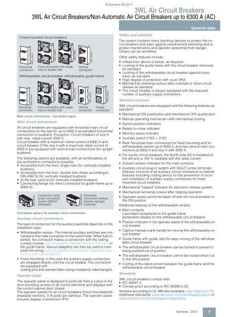
Fixed-mounted circuit breakers<br />
5 - ' $ % ><br />
Horizontal<br />
connection<br />
Horizontal<br />
connection<br />
Main circuit connections – connection types<br />
5 - ' $ & ><br />
Front connection with single<br />
hole or double hole<br />
Main circuit connections<br />
Vertical<br />
connection<br />
Withdrawable circuit breaker, withdrawable guide frame<br />
5 - ' $ % ><br />
All circuit breakers are equipped with horizontal main circuit<br />
connections on the rear <strong>for</strong> up to 5000 A as standard (horizontal<br />
connection to busbars). Exception: Circuit breakers of size II<br />
with max. rated current 4000 A.<br />
Circuit breaker with a maximum rated current of 6300 A and<br />
circuit breaker of the size II with a maximum rated current of<br />
4000 A are equipped with vertical main connections (<strong>for</strong> upright<br />
busbars).<br />
The following options are available, with all combinations of<br />
top and bottom connections possible:<br />
• Accessible from the front, single hole (<strong>for</strong> vertically installed<br />
busbars)<br />
• Accessible from the front, double hole (holes according to<br />
DIN 43673) (<strong>for</strong> vertically installed busbars)<br />
• At the rear, vertical (<strong>for</strong> vertically installed busbars)<br />
• Connecting flange (<strong>for</strong> direct connection to guide frame up to<br />
4000 A).<br />
5 - ' % # ><br />
5 - ' % ><br />
Front connection with single<br />
hole or double hole<br />
Connection using<br />
screw connection<br />
system (SIGUT)<br />
(standard)<br />
Vertical<br />
connection<br />
Flange<br />
connection<br />
Connection options <strong>for</strong> auxiliary circuit connections<br />
Auxiliary circuit connections<br />
The type of connection <strong>for</strong> the auxiliary switches depends on the<br />
installation type:<br />
• Withdrawable version: The internal auxiliary switches are connected<br />
to the male connector on the switch side. When fully inserted,<br />
the connector makes a connection with the sliding<br />
contact module (see the graphic "Guide Frame" in "Design") in<br />
the guide frame. Various adapters can then be used to complete<br />
the wiring (see the graphic "Connection Options <strong>for</strong> Auxiliary<br />
Circuit Connections").<br />
• Fixed mounting: In this case the auxiliary supply connectors<br />
are engaged directly onto the circuit breaker. The connectors<br />
are equipped with<br />
coding pins that prevent them being mistakenly interchanged.<br />
Operator panel<br />
The operator panel is designed to protrude from a cutout in the<br />
door providing access to all control elements and displays with<br />
the control cabinet door closed.<br />
The operator panels <strong>for</strong> all circuit breakers (fixed-mounted/withdrawable<br />
versions, 3-/4-pole) are identical. The operator panel<br />
ensures degree of protection IP41.<br />
5 - ' $ ' ><br />
5 - ' % ><br />
5 - ' % $ ><br />
5 - ' % ' =<br />
5 - ' % ><br />
5 - ' % ! ><br />
Screwless<br />
connection method<br />
(tension springs)<br />
(optional)<br />
Safety and reliability<br />
The system contains many blocking devices to protect the circuit<br />
breakers and plant against unauthorized switching and to<br />
protect maintenance and operator personnel from danger.<br />
Others can be retrofitted.<br />
Other safety features include:<br />
• Infeed from above or below, as required<br />
• Locking of the guide frame with the circuit breaker removed,<br />
as standard<br />
• Locking of the withdrawable circuit breaker against movement,<br />
as standard<br />
• High degree of protection with cover IP55<br />
• Mechanical reclosing lockout after overload or short-circuit<br />
release as standard<br />
• The circuit breaker is always equipped with the required<br />
number of auxiliary supply connectors<br />
Standard versions<br />
3WL circuit breakers are equipped with the following features as<br />
standard:<br />
• Mechanical ON pushbutton and mechanical OFF pushbutton<br />
• <strong>Manual</strong> operating mechanism with mechanical closing<br />
• Switch position indication<br />
• Ready-to-close indicator<br />
• Memory status indicator<br />
• Auxiliary switch 2 NO + 2 NC<br />
• Rear horizontal main connectors <strong>for</strong> fixed mounting and <strong>for</strong><br />
withdrawable version up to 5000 A, and rear vertical main connections<br />
at 6300 A and size II with 4000 A<br />
• For 4-pole circuit breakers, the fourth pole (N) is installed on<br />
the left and is 100 % loadable with the rated current<br />
• Contact erosion indicator <strong>for</strong> the main contacts<br />
• Auxiliary circuit plug-in system with SIGUT screw terminals<br />
Delivery inclusive of all auxiliary circuit connectors to internal<br />
features including coding device <strong>for</strong> the prevention of incorrect<br />
installation of auxiliary supply connectors <strong>for</strong> fixedmounted<br />
circuit breakers<br />
• Mechanical "tripped" indicator <strong>for</strong> electronic release system<br />
• Mechanical reclosing lockout after tripping operation<br />
• Operator panel cannot be taken off with the circuit breaker in<br />
the ON position<br />
Additional features of the withdrawable version:<br />
• Main contacts:<br />
Laminated receptacles in the guide frame,<br />
penetration blades on the withdrawable circuit breaker<br />
• Position indicator in the operator panel of the withdrawable circuit<br />
breaker<br />
• Captive manual crank handle <strong>for</strong> moving the withdrawable circuit<br />
breaker<br />
• Guide frame with guide rails <strong>for</strong> easy moving of the withdrawable<br />
circuit breaker<br />
• The withdrawable circuit breaker can be locked to prevent it<br />
being pushed out of position<br />
• The withdrawable circuit breaker cannot be moved when it is<br />
in the ON position<br />
• Coding of the rated current between the guide frame and the<br />
withdrawable circuit breaker<br />
Standards<br />
3WL circuit breakers comply with:<br />
• IEC 60947-2<br />
• Climate-proof according to IEC 60068-2-30.<br />
Versions according to UL 489 also available, see <strong>Catalog</strong> <strong>LV</strong> 16.<br />
Additional standards: www.siemens.com/lowvoltage/support or<br />
www.siemens.com/lowvoltage/configurators.<br />
<strong>Siemens</strong> · <strong>2012</strong><br />
7


