36 MB pdf download - VIR History
36 MB pdf download - VIR History
36 MB pdf download - VIR History

You also want an ePaper? Increase the reach of your titles
YUMPU automatically turns print PDFs into web optimized ePapers that Google loves.
NAYSHIPS 9T.O47<br />
s<br />
{t<br />
INSTRUCTTON BSOK<br />
for<br />
RF AND AF SIGI\TAL<br />
DISTRIBUTION UNIT<br />
AIRFLANE & MAruNE INSTRUMET{TS, INC,<br />
CLHARFIEI,D. PA.<br />
BUREAU OF SHTPS<br />
NAVY DEPAETTMENT<br />
*
NAV,SHIPS 91047<br />
RESTRICTED<br />
I TTSTRUCTION BOOK<br />
for<br />
tt<br />
RF AND AF SIGNAL<br />
IILSTRIBUTION UNIT<br />
AIRPLANE & MARINE INSTRUMENTS, INC.<br />
CLEARFIELD, PA.<br />
BUREAU OF SHIPS<br />
NAVY DEPARTMENT<br />
Contract: Nobsr ' 30,000 1948
Effective Poges<br />
NAVSHTPS 9rO47<br />
FRONT MATTER<br />
41<br />
LIST OF EFFECTIVE PAGES<br />
.i I<br />
1<br />
I<br />
'1 'r<br />
.l '<br />
'l-i<br />
.l\ * ,<br />
r'. 1 \<br />
\ il \<br />
t:t<br />
*tl<br />
-Li<br />
,t,-. -1<br />
'..:<br />
,r!;<br />
\i.-<br />
.. t r'{<br />
l<br />
t.j<br />
| .'<br />
\,<br />
f<br />
\ \ \<br />
I<br />
.,r1,<br />
i_,1"'-'<br />
PAGE<br />
NU'tABERS<br />
CHANGE IN I PAGE I CNANGE IN<br />
EFFECTITTU<strong>MB</strong>ERSEFFECT<br />
Title Page<br />
AtoC<br />
i to vii<br />
I-0 to I-24<br />
Original | 2-0 to 2-52 | Original<br />
Original I g-O to 3-8 , Original<br />
Original I 4-0 to 4-26 | Original<br />
Original<br />
,,f's<br />
\<br />
1<br />
A<br />
RESTRICTED ORIG!NA[.
FRONT MATTER, NAVSHTPS 9rO47 Promulgoting letter<br />
'/ .*"*$?' -^<br />
ttt"-<br />
"o1 1<br />
t'eq ^*o$l+'' ^^ ^ro:t$ *^ ''-^ ,rt** {'o" "t' -..**'<br />
,,o9.f ^+p-<br />
^"p*7frou f =<br />
^^^os' ^o n*.}-o<br />
'SRiGf NAt<br />
R,ESTRICTED
Correction Poge<br />
NAVSHTPS 9rO47<br />
FRONT $AT I cR<br />
RECORD OF CORRECTIONS MADE<br />
CHANGE NO.<br />
DATE<br />
SIGNATURE OF OFFICER MAKING CORRECTION<br />
I<br />
l--<br />
I<br />
c<br />
RESTRICTED<br />
ORIG!NA]
Fr r tP1 +IATTER NAVSHTPS 9rO47 Contents<br />
TABLE OF CONTENTS<br />
I<br />
f';:'" .<br />
SEeTIOr\i |<br />
-GENERAI<br />
DESCRIPTION<br />
't'<br />
t"ltl#escriPtion<br />
c. Overall Function<br />
d. Features<br />
2. N{ajor Typ" Units and Associated Equipment<br />
:t,. Types<br />
(1) Typ" A Unit<br />
(2) Typ" B Unit r<br />
(3) Typ" C Unit<br />
3. Components of the Signal Distribution<br />
Units<br />
n. Standard Components<br />
(1) Cabinet AN TYPE CY-597 /C<br />
( a) Blank Panels<br />
/- [;i ;:'':"lJ:il'$il;:T;'-tiS4/G<br />
( c,) Connector-Adapter, Navy Typ"<br />
cr[-491652<br />
(4) Jack Panel AN Type J-238/C<br />
( a) jack Box Navy Typ" CIA-<br />
491729<br />
(5) Switch Panel AN Types SA-f<strong>36</strong> /G,<br />
SA-I37 /C, and SA-138 /C<br />
( a) Arttenna Selector Switch AN<br />
Types, SA-139/U<br />
(6) ]ack Panel AN Typ" I-239/C<br />
( a) RF Jack Switch Navy Typ"<br />
CIA.491388<br />
(7) Jack Panel AN Typ" I-237 /G<br />
(S) Control AN Typ" C-443/G<br />
(9) Terminal Board Assembly AN Typ"<br />
I-212/C<br />
(10) ]ack Mountittg Strip, Navv Typ"<br />
-491394<br />
( a) Receiver Output Panel<br />
(b) Miscellaneous Apparatus Panel<br />
(ll) Retair ier-Pull"y Assembly AN<br />
Typ" MX-813/C<br />
(12) Patchcord Storage Panel AN Typ"<br />
rux-814/G<br />
(I3) Switch Panel AN Typ" SA-f35 /C<br />
( n) K"y Compartrnent<br />
(b ) Atr Channel Selector Switch,<br />
Page<br />
1-1<br />
1-1<br />
r-1<br />
t-1<br />
t-1<br />
r-2<br />
L-2<br />
L-2<br />
L-2<br />
L-2<br />
1-3<br />
I-3<br />
r-s<br />
L-4<br />
L-4<br />
L-4<br />
L-4<br />
r-5<br />
1-5<br />
1-6<br />
L-7<br />
L-7<br />
r-7<br />
r-7<br />
1-B<br />
1-B<br />
1-B<br />
1-9<br />
l-9<br />
l-9<br />
1-10<br />
r-10<br />
1-10<br />
v<br />
Paragraph<br />
Page<br />
Navy Typ" CSM -24L259 1-11<br />
(14) Speaker Assembly AN Typ"<br />
LS-r39 /C<br />
l-tr<br />
(15) Ohmmeter Navv Model ZM-L/U L-Iz<br />
(16) Volt - Ohm - Milliammeter Navy<br />
Model OBQ-4<br />
(17) Frequency Meter Navy Model<br />
L-Lz<br />
LR.l<br />
T-Lz<br />
(a) Mountitrg AN Typ" MT-57L/G 1-I3<br />
(t,) Jack Panel AN Typ" I-265/G 1-13<br />
(18) Volume Level Indicator AN Typ"<br />
T5.629/ U<br />
(19) Frequency Meter Navy Model<br />
LN{-15a<br />
(20) Cathode R"y Oscilloscope Navy<br />
Model OBL-3<br />
L-L4<br />
l-I4<br />
I-L4<br />
(21) Navv N{odel RBC Receiver I-I4<br />
(a) Porver Supply Navy Typ" CRV-<br />
20130 For RBC Receiver 1-15<br />
(22) Switchboard Shelf AN Typ"<br />
FN-28/G 1-15<br />
4. Reference Data l-f 6<br />
SECTION 2-INSTALLATION AND OPERATION<br />
1. Installation 2-L<br />
ct . General 2-L<br />
lr. Location of Signal Distribution Units 2-I<br />
c. Unpacking and Handliug of Cornponents<br />
2-L<br />
d,. Preparation of Mounting Surface 2-l<br />
e. Installation of Antenna Lead-Ins 2-3<br />
(I) Method I, Installation of Connector-Adapters<br />
Navy Typ" CIA-<br />
49L652 Within the Cabinets AN<br />
Typ" CY-597 /G 2-3<br />
(2) Method 2, Installation of Connector-Adapters<br />
Navy Typ" CIA-<br />
491652 Outside the Cabinets AN<br />
Typ" CY-597 /G 2-g<br />
f . Installation of the Cabinets AN Typ"<br />
cY-5e7 /C 2-3<br />
g. N,Iounting of Components 2-3<br />
'lL.<br />
Internal Wiring 2-6<br />
(1) Antenna Lead-Ins 2-9<br />
(2) RF Wiring 2-g<br />
(3) AF Wiring 2-I0<br />
ORIGINAI<br />
RESTRICTED
Contents<br />
NAVSHIPS 91047<br />
FRONT MATTER<br />
Paragraph<br />
( u) AF Jack Panels<br />
(b) Terminal Boards<br />
( c) AF Selector Switch Wiring<br />
i. External Interconnecting Cables<br />
(t) RF Wiring<br />
(2) Operator's Position<br />
(3) External AF Wiring<br />
i. Primary Power Connections<br />
k. Installation Tests<br />
(1) Continuity Tests<br />
(2) Insulation Tests<br />
l. AF |umper Cables<br />
nL. Marking<br />
(1) RF Circuits<br />
(2) AF Circuits<br />
n. Moisture Proofing Around Cut-Outs<br />
2. Operation<br />
&. General<br />
b. Operating Procedure, RF Section<br />
(1) "Normal Through" Operation<br />
(2) Parallel Connections<br />
(3) Switching Receiver Inputs<br />
(4) Use of the Multicoupler With the<br />
Signal Distribution Unit<br />
(5) Use of the Antenna Selector Switch<br />
(6) Monitor Receiver<br />
(7) Frequency Meter<br />
c. Operating Procedure AF Section<br />
(1) "Normal Through" Operation<br />
( a) "Normal Thr:ough" Circuit Alterations<br />
(2) Patching Operation<br />
( a) Parallel Patching<br />
(b) Load Exchange Patching<br />
7. Substitution of Loads<br />
2. Two Audio Inputs to One Load<br />
3. Combination Load Exchange<br />
and Parallel Patching<br />
d. Speaker Panel<br />
e. Control AN Typ" C-443/G<br />
f . Test Equipment<br />
SECTION 3_MAINTENANCE<br />
l. Operator's Maintenance<br />
cL. Cleaning<br />
Page<br />
2-r0<br />
2-L2<br />
2-L2<br />
2-r4<br />
2-I4<br />
2-L4<br />
2-r4<br />
2-L6<br />
2-L6<br />
2-L6<br />
2-L6<br />
2-L6<br />
2-L6<br />
2-L9<br />
2-L9<br />
2-L9<br />
2-L9<br />
2-L9<br />
2-20<br />
2-20<br />
2-20<br />
2-2L<br />
2-2L<br />
2-2L<br />
2-2L<br />
2-22<br />
2-22<br />
2-22<br />
2-23<br />
2-22<br />
2-24<br />
2-24<br />
2-21<br />
2-24<br />
2-21<br />
2-26<br />
2-26<br />
2-27<br />
3-1<br />
3-1<br />
3-1<br />
Paragraph<br />
c. Ventilation<br />
2. Preventive Maintenance<br />
cL. Inspection<br />
(l ) Overheating<br />
(2) Placernent<br />
(3) Cleanliness<br />
(4) Tightness<br />
b. Routine Tests and Checks<br />
(t) Insulation Tests<br />
(2) Cround Tests<br />
(3) Ventilator Screens<br />
(4) Ground Connections<br />
(5) Electronic Components<br />
(6) AF Patchcords<br />
(7) Crounding of Shields<br />
(B) Tropicalization<br />
(9) Re-Tro picalization<br />
c. Corrective Maintenance<br />
(1) Wiring<br />
(a) Ground or Partiallv Grounded<br />
Circuits<br />
(b) Crounds in*k AF Section<br />
( c.) Crounds in the RF Section<br />
( d) Shorted or Crossed Circuits<br />
( e) Open Circuits<br />
( f ) Improperly Grounded Shield in<br />
AF Section<br />
( g ) Improperly Grounded Shield in<br />
;. RF Section<br />
(2) Antenna Selector Switch, Trouble<br />
Shooting<br />
(3) Antenna Selector Switch, Corrective<br />
Action<br />
(4) AF Selector Switch Navy Typ"<br />
CSM-2 4L259, Trouble Shooting<br />
(a) Short Circuits<br />
( b ) High Contact Resistance<br />
( c) Lack of Continuity On All Positions<br />
( d) Lack of Continuity on One<br />
Position<br />
( e) Improper Detent Action<br />
( f ) Wafers Mechanically Damaged<br />
(5) RF Jack Switch Navv Typ" CIA-<br />
491388<br />
(6) Connector-Adapters Navy Type<br />
CIA-49T652<br />
Pu"ge<br />
3-1<br />
3-r<br />
3-2<br />
3-2<br />
3-2<br />
3-2<br />
3-2<br />
3-3<br />
3-3<br />
()o<br />
o-o<br />
3-B<br />
oct<br />
o-o<br />
3.3<br />
3-3<br />
c()<br />
trO<br />
l-,-3<br />
o-3<br />
3-4<br />
3-4<br />
3-4<br />
3-4<br />
3-ti<br />
3-4<br />
3-5<br />
o-D<br />
3-5<br />
3-5<br />
oe<br />
r' ;t<br />
o4<br />
o-/<br />
o4<br />
o-l<br />
3-8<br />
3-B<br />
3-B<br />
3-B<br />
3-8<br />
3-B<br />
3-8<br />
RESTRICTED<br />
ORIGINAL
FRONT MATTER NAVSHTPS 9rO47 lllustrqtions<br />
LIST OF ILLUSTRATIONS<br />
SECTION I DESCRIPTION<br />
Figur -GENERAL Ti!,le P age<br />
1-1 iignal Distribution Unit Typ" A Assem-<br />
bled For Operation<br />
L-2 Cabinet, AN Ty"p" CY-597 /G, Rear View<br />
i-3 Switch Panel AN Typ" SA-134 /G, Installed<br />
in Cabinet AN Typ" CY-597 /G<br />
I 4 Jack Panel AN Typ" I-243/C With Connector-Adapters<br />
Navy Typ" CIA-<br />
49L652 in Place<br />
1-5 Jack Panel AN Typ" I-238/C, Front<br />
View<br />
1-6 Jack Box Navy Typ" CIA-49L729, Part<br />
of I-238/G, Isometric View With<br />
Cover Removed<br />
7-7 Switch Panel AN Typ" SA-138/C, Front<br />
View<br />
1-B Antenna Selector Switch. AN Typ" SA-<br />
I40/I. Cutawa' View<br />
l-y Jack t,, .r AN Typ" I-239/C, F'ront View<br />
With One Rtr Jack Switch Navy<br />
'^'yp., CIA-491388 Rernoved<br />
1-f0 RF Jack Srvitch Navy Typ" CIA-491388,<br />
Functional Diagram<br />
l-f I Jack Panel AN Typ" J-237 /G, Front<br />
View With One Jack AN Typ" UC-<br />
294/tJ Removed<br />
I-I2 Control AN Typ" C-443/C, Front View<br />
t-13 Terminal Board Assembly AN Typ"<br />
I-242/C, Rear View<br />
L-L4 Jack Mounting Strip Navy Typ" -49L394,<br />
Front View With One ]ack Navy Typ"<br />
-491395 Removed<br />
1-15 Retainer-Pull"y Assembly, AN Typ"<br />
MX-BL}/C<br />
1-16 Patchcord Storage Panel, AN Type<br />
N4X-814/ C, Front View<br />
L-L7 Switch Panel AN Typ* SA-135 /C, F'ront<br />
View<br />
1-IB K")' Compurtment, Part of Switch Panel<br />
t-19<br />
r-20<br />
I-27<br />
AN Typ" SA-135 /C<br />
AF Channel Selector Switch. Nrvv Typ*<br />
CSM -24L259<br />
Speaker Assembly AN Typ" LS-f39/C,<br />
Front View<br />
Ohmmeter Navy llodel ZM-L/IJ, Front<br />
\'"-i.ew<br />
t-0<br />
L-2<br />
1-3<br />
L-4<br />
1-5<br />
r-5<br />
1-6<br />
r-6<br />
L-7<br />
L-7<br />
1-8<br />
1-B<br />
1-9<br />
1-9<br />
1-9<br />
1-r0<br />
1-10<br />
1-i I<br />
1-11<br />
1-1 t<br />
L-I2<br />
Figure Title Page<br />
L-22 \/olt-Ohm-Milliammeter Navv Model<br />
J<br />
oBQ-4<br />
L-Lz<br />
L-23 Frequency Meter Navy Model LR-l<br />
Mounted in Signal Distribution Unit L-Lz<br />
I-24 Mounting AN Typ" MT-57L/G,Isometric<br />
View 1-13<br />
I-25 Ju:k Panel AN Typ" I-265/G, Front<br />
View With One Adapter AN Typ"<br />
UC-294/U Removed 1-13<br />
L-26 \'olume Level Indicator, AN Typ" TS-<br />
629/tJ, Front View<br />
L-27 Frequency NIeter Navy Model LM-15a,<br />
Front View<br />
1-28 Cathode Ruy Oscilloscope, Navy Model<br />
OBL-3a, Front View<br />
l-29 Radio Receiver Navy Model IIBC-2,<br />
Mounted in Rack Mounting Cabinet<br />
Navy Type -fm50, Front View<br />
L-L4<br />
L-L4<br />
I-L4<br />
L-L4<br />
1-30 Power Supply Navy Typ" CRV-20130<br />
For Use With Navy Model RBB/RBC<br />
Radio Receiver, Rear View 1-15<br />
I-31 Switchboard Shelf AN Typ" FN-28/G<br />
Mounted on Front of Cabinet 1-f5<br />
SECTION 2-INSTAIIATION AND OPERATION<br />
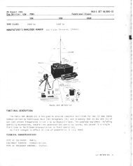
2-L Typical Station Floor Plan Showing<br />
Location of Signal Distribution Unit 2-0<br />
2-2 Drilling and Cutting Plan for Preparation<br />
of Mountitrg Surface for Signal<br />
Distribution Unit 2-2<br />
2-3 Installation of Connector-Adapter Navy<br />
Typ" CIA-49L652 on Cable AN Typ"<br />
RC.Bs,/U 2-4<br />
2-4 Cable Support for RG-85 /V Cable Fabricated<br />
Accorditrg to BuShips Drawing<br />
RW6F<strong>36</strong>6D 2-5<br />
2-S Cable Vault Fabricated Accorditrg to Bu-<br />
Ships Sketch #977F3-K1-B Dated 15<br />
August 1947 2-6<br />
2-6 Signal Distribution Unit Typ" A Showitrg<br />
Internal Wiring 2-7<br />
2-7 Signal Distribution Unit Type A, Ilear<br />
View Showing Connector-Adapters<br />
Navv Typ" CIA-49I652 Installed in<br />
the Cabinets 2-B<br />
GRiGINAT<br />
U<br />
RESTRICTED<br />
ltl
lllustrotions qnd Tobles<br />
NAVSHTPS 91047<br />
FRONT V1ATTER<br />
F igure<br />
T itle<br />
2-B Installation of Connectors Nar,'y Typ"<br />
-49f 90 on RC -LL/IJ Cable<br />
2-9 Typ" A, Close-Up View of RF Cabinet<br />
Wiring With Connector-Adapters<br />
Navv Typ" CIA-49L652 Installed in<br />
Cabinet<br />
2-I0 Typ" A, Close-Up View of AF Cabinet<br />
Wiring<br />
z-LI Typ" A, Close-Up View of AF Cabinet<br />
Wiring Showing Method of Lacing<br />
and Clampitrg<br />
2-I2 AF ]ack Panel Wired Using Thomas and<br />
Betts Grounding Ferrules #200-30006<br />
2-13 Close-Up Showing Method of Wiring<br />
Telephone Jacks on llear of Jack<br />
Mountittg Strips Navy Typ" -491394<br />
2-L4 Top View Showing Alternate Method of<br />
Mountitrg Terminal Boards<br />
z-LS Fabrication of Internal AF Wiring Using<br />
Thomas and Betts Groundin! Ferrules<br />
#2A080006<br />
2-16 Terminal Board Wired Using N{odified<br />
TTRS Cable and Thomas and Betts<br />
Grounding Ferrules #200-30006<br />
2-I7 Primarv Power Distribution<br />
z-LB Overall Functional Block Diagram (AF<br />
and RF)<br />
2-I9 RF Circuits Showing "Normal Through"<br />
2-20 - JL1,.Y,T*' ;:* *nff;;r"'"To<br />
p e r ati o n<br />
of Two Receivers From One Antenua<br />
2-21 Wiring Convention, AF Section<br />
2-22 "Nonnal Through" Operation, AF Section<br />
2-23 Changittg "Normal Through" Circuits<br />
By Altering Flexible Connections<br />
Page<br />
2-9<br />
2-L0<br />
2.LL<br />
2-L2<br />
2-I3<br />
2-r3<br />
2-r1<br />
2-L5<br />
2-L6<br />
2-r7<br />
2-LB<br />
2-L9<br />
2-20<br />
2-22<br />
2-22<br />
2-23<br />
Figure T t,lie l' _t.:la<br />
2-24 Wiring Convenlitln F-,-rr r,,' Jack Panel:, 2-23<br />
2-25 Operation of A tr Pr.i ,ircori.ls 2-21<br />
2-26 Substitution ol' Load Circ '' C | 't F<br />
Circuit A Z-25<br />
2-27 Combination Load Exc,hange and Far-<br />
allel Patching<br />
2-28 Speaker Assembly AN Typ" LS-139 /G,<br />
Schematic<br />
2-29 Control AN Typ" C-443/G, Scherr tfic<br />
2-30 RF Cabinets, Internal Wiring L)i tgrarn,<br />
Typ" A<br />
2-31 T,,rp" A. Outline Dimensions<br />
2-32 J1,pe B^ Outline Dimensions<br />
2-33 'f',u:p" C, Outline Dimernsions<br />
2-34 Typ" A, Pictorial<br />
2-35 f'yp" B, Pictorial<br />
2-<strong>36</strong> Typ" C, Pictorial<br />
2-37 Ty.pe A, Interconnecting Diagram<br />
2-38 Tvpe B, Interconnecting Diagram<br />
2-39 Type C, Interconnectitrg Diagram<br />
2-40 Typical Connection Diagram, AF Section<br />
2-4I Tvpical Connection Diagram, RF Section<br />
SECTION 3-MAINTENf,\NCE<br />
2-25<br />
2-24<br />
2-26<br />
2-29<br />
2-3I<br />
2 -33<br />
)1-35<br />
2-37<br />
2-39<br />
2-4L<br />
2-43<br />
2-45<br />
2-17<br />
2-19<br />
2-5r<br />
3-1 Frrse Locations in Prirnary Power Distri-<br />
"'.o bution Panel SA-134/C 3-2<br />
3-2 Antenna Selector Srn'itch AN Typ" SA-<br />
L40 /lJ, Ctrteway 3-6<br />
3-3 Stationarv Contact Partially Rernoved<br />
From 'Contact Ring 3-7<br />
3-1 Cutaway View of Rotor End Contact<br />
Assernbly 3-7<br />
LIST OF TABLES<br />
SECTION I DESCRIPTION<br />
Figure -GENERAL Title<br />
1-1 Equipmetrt Supplied, Typ" A Unit<br />
L-2 Equipmeut Supplied, Type B Urtit<br />
f-3 Equipment Supplied. Typ" C Unit<br />
I-4 Ecluiprnent and Ptrblications Recluired<br />
But Not Supplied TYP" A Unit<br />
1-5 Equipment and Publications Required<br />
But Not SupPlied, TyPe B Unit<br />
f -6 Equipmeut and Publications Required<br />
But Not Supplied, TvPe C Unit<br />
L-7 Shipping Data<br />
Page<br />
r-r7<br />
I.TB<br />
1- 19<br />
r-20<br />
L-2L<br />
r-22<br />
1-23<br />
SECTION 2-INSTALTATION AND OPERATION<br />
Figure Title Page<br />
2-I Tools lle'iuired for Installartjon 2-27<br />
SECTION 4-PARTS LIST<br />
4-L Weights and l)imensions of Spare Parrs<br />
Roxes<br />
4-2 List of Major Units<br />
1-3 Combined Parts and Spare Parts List<br />
4-4 Cross Reference Parts List<br />
4-5 List of Manufact,rrer',!<br />
4-0<br />
1-r<br />
4-,3<br />
4-26<br />
4-26<br />
iv<br />
RESTRICTED<br />
(}lil('l^tAI
FRONT YIATTER NAVSHTPS 91047 Guqrqnlee qnd Instqllcrtion Record<br />
GUARANTEE<br />
i 're<br />
Contractor guarantees that at the time of delivery thereof the articles provided for under this contract<br />
will '- r fr. e lrom any defects in material or workmanship and will conform to the requirements of this contract.<br />
Notice of 'n,v such defect or non-conformance shall be given by the Government to the contractor within one<br />
year of the delivery of the defective or nonconforming article, unless a different period of Guarantee is<br />
specified in ti.e schedule. If required by the Government within a reasonable time after such notice, the Contraetor<br />
shall with all possible speed correct or replace the defective or noncomforming article or part thereof.<br />
When ' :h correction or replacement requires transportation of the article or part thereof, shipping costs, not<br />
excee\r .5; usual charges, from the delivery point to the Contractor's plant and return, shall be borne by the<br />
Co- :tor; the Government shall bear all other shipping costs. This Guarantee shall then continue as to corrected<br />
or replacing articles or, if only parts of such articles are corrected or replaced, to such corrected or replac;ng<br />
parts, until one vear after the date of redelivery, unless a different period of Guarantee is specified in the<br />
schedule. If the Government does not require correction or replacement of a defective or non-conforming<br />
article, the Contractor, if required by the contracting officer within a reasonable time after the notice of defect<br />
or non-conformance, shall repav such portion of the contract price of the article as is equitable in the circumstances.<br />
INSTALLATION RECORD<br />
Contract Number NObsr-30,000 Date of Contract, 23 April 1946<br />
Serial Number "f<br />
equipment. . .<br />
Date of acceptance bg the Nat)a. .<br />
Date of delit)era to contract destination .<br />
Date of completion "f<br />
installation<br />
[]ate placed in sert)ice<br />
blank spaces on this page shall be filled in at time of installation. Operating personnel shall also mark the<br />
"date 1,ln,,ed in service" orr the date of acceptance plate located below the model nameplate on the equipment,<br />
using suiiab.lc method.r and care to avoid damaging the equipment.<br />
OR GIN It<br />
?<br />
RESTRICTED<br />
V
Miscellqneous Dotq<br />
NAVSHTPS 9rO47<br />
REPORT OF FAILURE<br />
Report of failure of any part of this equipment, during its entire service life,'shall be :ade' fhe Surerrtr of<br />
Ships in accordance with current regulations using form NAVSHIPS NBS 383 (revised) except fr v'iar'ine t. .rps<br />
equipment, in which case the "Signal Equipment Failure Report" form shall be used and disti, r -ed in ai:, rrdance<br />
with instructions pertaining thereto. The report shall cover all details of the failure and give the date ',<br />
f iirstallation<br />
of the equipment. For procedure in reporting failures see Chapter 67 of the Bureau oJ Sluips Mt:nual<br />
or superseding instructions.<br />
ORDERING PARTS<br />
All requests or requisitions for replacement material should includerthe following data:<br />
1. Federal stock numbe, o., *hei ordering from a Marine Corps # Signal Corfs ,rrpply depot, tirt' Signal<br />
Corps stock number.<br />
2. Name and short description of part. :<br />
1<br />
If the appropriate stock number is not available the following shall be specified:<br />
t. Equipment model or type designation, circuit symbol, and item number.<br />
2. Name of part and complete description.<br />
3. Manufacturer's designation.<br />
4. Contractor's drawing and part number.<br />
5. JAN or Navy type number.<br />
DESTRUCTION CF<br />
ABANDONED MATERIAL {N THE CO<strong>MB</strong>AT ZONE<br />
In case it should become necessary to prevent the bapture of this equipment, and when orclered to do so,<br />
DESTROY IT SO THAT NO PART OF IT CAN BE SALVAGED, RECOGNIZED, OR USED BY THE<br />
ENEMY. BURN ALL PAPERS AND BOOKS.<br />
Means:<br />
1. Explosives, when provided'<br />
2. Hammers, axes, sledges, rnachetes, or whatever heavv object is readilrz available.<br />
3. Burning by means of incendiaries such as gasoline, oil, paper or wood.<br />
4. Grenades and shots from available firearms.<br />
r<br />
5. Burying all debris, where possible and when time perrnits.<br />
6. Throwing overboard or disposing of in streams or other bodies of water.<br />
Proced,ure:<br />
L Obliterate all identifying marks. Destroy nameplates and circuit labels.<br />
2. Demolish all panels, castings, switch and instrument boards.<br />
'].<br />
3. Destroy all controls, switches, relays, connections and meters.<br />
4. Rip out all wiring and cut interconnections of electrical equipment Smash gas, oil, and water cooir1i'."<br />
systems in gas engine generators, etc.<br />
5. Smash every electrical or mechanical part, whether rotating, moviirg or ffxed<br />
6. Break up all operating instruments such as keys, phones, microphones, etc.<br />
7. Destroy all classes of carrying cases, straps, containers, etc.<br />
8. Bury or scatter all debris.<br />
DESTROY EVERYTHING!<br />
RESTRICTED<br />
fitttl-,r NAI-
[:'::N MAT'TER NAVSHTPS 9rO47 Sofety Notice qnd Resuscitqtion<br />
'i i..;i-l atlr.rli "rrl , (,f OffiCe.'S i, ! i1 I -eratit'g pefsonnel iS<br />
dir(-,*',,r, t.l ."-'har i;.r 67 of ', -, l, 'REAU QF SHIPS<br />
N{Ai,il' .i.. c: sup( , 'r.ling instructions on the subiect<br />
of r tdio -s. .i ety ;)recai'<br />
" nns to be observed.<br />
'I,'r:is e(, ,;;, 'nt enri .oys voltages (1200 volts) which<br />
ar€ langelou nf may he fatal if contacted by operatit,<br />
I liersonrre.!. Extreme caution should be exerciseci<br />
when working with the equipment.<br />
Wiri]e ever)i practicable safcty precaution has been<br />
inccrporated in this equipment, the followittg rules<br />
mt st be strictl , otrserved:<br />
KEE} I flAY FROM LIVE CIRCUITS:<br />
Op" atrng personnel must at all time observe all<br />
tsf"tv regulptior.s. Do not change tubes or make adjtist<br />
erlts inside ')quipment.with high voltage supply<br />
o1r. T l'*Jr certain conditions dangerous potentials<br />
',may<br />
exfst r circuits with po!\'er controls in the off<br />
positi,rn dr to charges retatned by capacitors. To<br />
SAFETY NOTICE<br />
RESUSCITATION<br />
AN APPROVED POSTER ILLUSTRATING THE<br />
RULES FOR RESUSCITATION BY THE PRONE<br />
PRESSURE METHOD SHALL BE PROMINENTLY<br />
DISPLAYED IN EACH RADIO, RADAR, OR<br />
SONAR ENCLOSURE. POSTERS MAY BE OB-<br />
TAINED UPON REQUEST TO THE BUREAU<br />
OF }IEDICINE AND SURGERY.<br />
avoid casualties always renrove power and discharge<br />
and ground circuits prior to touching them.<br />
DON'T SERVICE OR ADJUST ATONE:<br />
Under no circumstances should any person reach<br />
within or enter the enclosure for the purpose of servicing<br />
or adjusting the equipment rvithout the immediate<br />
presence or assistance of arrother person capable<br />
of rendering aid.<br />
DON'T TAMPER WITH INTERIOCKS:<br />
Do not depend upon door switches or interlocks<br />
for protection but always shut down motor generators<br />
or other power equipment. Under no circurnstances<br />
should any access gate, door, or safety interlock switch<br />
be removed, short-circuited, or tampered with in any<br />
w?/, by other than authorized mtrintenance personnel,<br />
nor should reliance be placed upon the interlock<br />
switches for removitrg voltages fronr the equipment.<br />
WARNING:<br />
NEVER MEASURE POTENTIALS IN EX-<br />
CESS OF IOOO VOLTS BY MEANS OF<br />
FLEXIBLE TEST }LEADS<br />
OR PROBES.<br />
RESTRICTED<br />
vii
1<br />
Section NAVSHIPS 91047<br />
t<br />
GENERAL DESCRiBTION<br />
a,<br />
Figure l-1. Signol Distribution Unit Type<br />
RESTRICTED<br />
A Assembled For Operotion<br />
t<br />
r llrcliiAt
GENIJ IAL ()<br />
DESCRlPTtOr.l<br />
NAVSHIPS 9rO47 Section 1<br />
Porogroph I<br />
f<br />
4-tr'<br />
sEcTroN 1<br />
GENERAL DESCRIPTION<br />
t'. t .'<br />
a<br />
I. GENERAL DESCRIPTION. r4B-f<br />
cL. PURFOSE -fh6 Navy Sigqal Distribution Unit<br />
, ^ is a standa cil:BF and AF't'lnanually operated<br />
-'ct t .r<br />
tftur ti'Amfrg ar', I trCdt;nng equipment:fur use in Naval<br />
:*.t'5[gr€<br />
col]t- r,, rnication,centers.<br />
equiprntn t .&mitJ' standardization of compon-<br />
-thods of , stallation and l, ittg of AF lrd RF<br />
slgna :rc'--is, r. -d . provides ma .-i a "irnum<br />
.r^<br />
operational<br />
fexibr,,i \,,L ^:] ;.'.+ff I i'l<br />
lw. ''<br />
r<br />
{*t<br />
J-b<br />
+ ')EsIf;<br />
>,J_\:r: - fd mee +L requir its of paragit.<br />
r.. I, &, .darCized 'r-rr-e available<br />
from rvzv/<br />
'<br />
s which have bec .<br />
r+in<br />
sraL.Iard r relay rack -:.h' . i., ly .<br />
desired<br />
order. Blani.<br />
p&IlSlt,rl .'ru Z.'J,<br />
necesgl lo.<br />
obtaihd' ' lI<br />
orization.<br />
The Typ. A Sigr ' Dist.'ibution Unit, which con-<br />
;ists of three caL,^ret. s t";scribed in this section.<br />
Type.s B and C are similar in ccnstruction but consist<br />
of two :nd -.r€ cabinet 'resF:cl'.'el:2. Basic operating<br />
procer',trrc- ld components are the sarne for all three<br />
types, but the numl-or arrar\peme.,., and mounting of.<br />
li<br />
; curnp( rent: ',lre alte- ,J to ftt trre space available.<br />
^c" J"/ERALL F -ICTIOI{"-Tire Signal Distributfrr<br />
Unit consists of twc sections, the ttadio Frequency<br />
lRh and the Audio Frequ€r..-, (AF). Suitable monitoring<br />
equipment is included.<br />
I to mount 'f<br />
r 'l space is i", *r"" iled -v permit ex-<br />
- \al comp^.-.ent<br />
?A " .1Uired. The<br />
'fent furni hed coirrponents may be<br />
' - iy su^:ply . rrce . proper auth-<br />
,n<br />
fD T nc RF section provid€s co', ction facilities for all<br />
'- *fttennae of the station network. Ihe internal wiring<br />
is such that "normal through" cirn' its from antennae<br />
to statior: r eceivers andi or multr. plers are used.<br />
Howe\zer, suitable panels and patchcords permit the<br />
' op"#tion of any receiver or multicoupler from any<br />
station l::rtenna. In addition, the normal signal source<br />
to a re :civer inay be interrupted, and the signal obtainert<br />
from a different source which may be either<br />
a multicoupior or an antenna. A rotary antenna selector<br />
.witch is provided which permits rapid comparison<br />
of :, ntennae to determine the best input response for<br />
a particul.rr signal by comparison of reception on variorrS<br />
antc -,o.e of the network. The antenna selector<br />
switc.h _il"V also be used to determine roughly the ,'<br />
oR1,';lrvBt<br />
bearing of a given signal or interlse noise source, provided<br />
the antenna network coverage is sufficiently<br />
large and the transmission lines have approximately<br />
the same attenuation characteristics.<br />
The AF section provides connection facilities for the<br />
audio outputs of the station receivers. Direct 'normal<br />
through" circuits connect the receiver outputs to their<br />
normal loads. An arrangement of jack panels and<br />
suitable AF patchcords permits the normal load circuits<br />
to be switched so that any receiver can be connected<br />
to any load with minimum interruption. Or,<br />
if so desired, the normal load circuit of a receiver may<br />
be connected to another load in parallel for monitoring<br />
without interrupting communications. The interconnecting<br />
terminal boards, in series between receiver<br />
output terminal boards and connected load terminal<br />
boards, furnish a means for making tempo rary or permanent<br />
circuit connections to eliminate the use of<br />
patchcords in permanent or semi-permanent circuits.<br />
An audio frequenc;r selector switch with parallel connections<br />
frorn the receiver output terminal boards is<br />
used to tnonitor or rneasure any receiver output circuit<br />
without interrupting connections.<br />
Patchcord switching enables the operator to set up<br />
circuits other than the "normal through" circuits as<br />
desired. However, since the needs of individual stations<br />
differ, the system must be adapted to the specific<br />
case.<br />
RESTRICTED<br />
d. FEATURES.-In each type of the Signal Distribution<br />
unit, provision is made for mounting Government<br />
furnished equipments which may be used to<br />
measure frequency, insulation resistance, volume level,<br />
voltage, and current, and provide visual and aural<br />
monitoring. The Signal Distribution units are wired<br />
for a 1r5 volt AC power solrrce. Switch panel AN<br />
Typ" SA-r34 / C mounts in the rear of each cabinet to<br />
serve as a fused primary power line control. Each<br />
cabinet contains convenience outlets on the front and<br />
rear, a strip outlet with a common ON-OFF Switch<br />
for electrically operated components, and a trouble<br />
light. A writing shelf and a dual utility speaker<br />
panel are included for use by the operator.<br />
The Typ" A unit provides space for a Navy Model<br />
RBC Radio Receiver with Power Supply Unit Navy<br />
Type CRV-20130 for 1L0/rL5/rz0 VAC operation.<br />
1-1
1 Section<br />
Porogroph I d<br />
NAVSHTPS 9rO47<br />
GE. li;itAl<br />
Dni,'R' r'lcN<br />
This receiver is intended prirn.i 'ly foi nr(<br />
purposes.<br />
Lr-I$<br />
Figure | -2. Cobinel,<br />
1-2<br />
AN Type CY-597 /G, Reqr View<br />
RESTRICTED<br />
2. MAJOR TYPE UNITS AND ASSOCIATED FT P.<br />
MENT.<br />
cL. The Signal Distribution Unit is furrrishld *,^ .,'rree<br />
types to suit the needs of different size stat:or.q. The<br />
components mounted in each type unil a, interchangeable<br />
with the components in the other two<br />
types. The units are designated as Types A, B, and C.<br />
Types may be readily converted to the larger or<br />
smaller size by rearrarrgement and irddition of eer \,-<br />
ponents.<br />
' 'Ft<br />
(1) TYPE A UNIT.-The typ" A S,,: al Distribrrtion<br />
Llnit, used singly or in rnultiple, is *.esigned to<br />
meet the needs of the largest shore cornmrrnication<br />
centers. Provision i,s rnade for connecting thirty-two<br />
antennae and thirtv-two receil-ers. The Typ" A Unit,<br />
consisting of three cabinets, is approxinrately 67 J /B<br />
inches wide, 26 inches Ceep, and 87 9/16 iuches high<br />
wherr completely assembled. A typi .l Typ. A installation<br />
includes the components list..' in Table I-I<br />
arrd Table I-1. See figure 2-31 for the arlandement<br />
of cornpclnents.<br />
(2) TYPE B UNIT.-The Typ" Il Signal Distribution<br />
Unit is designed to meet the needs of a medium<br />
size shore communication center. Provision is made<br />
for connecting twenty-two antennae and trventy-two<br />
receivers. The T)'p" ts Urrit, consistit g of two cabinets,<br />
is approxirnately 443/4 inches wide, 26 inches<br />
deep, and 87 I / 16 inches high. Shoulcl the needs of<br />
a meditrm sized station expand so that twenty-two<br />
,circtrits are instrfficient, the T1'pe B Unit can easily he<br />
converted to a Type A Unit merelv bv the addition of<br />
olre cabinet and the necessary components and rearrangement<br />
of the cornponents within the three cabinets.<br />
The cabinets are identical with those used in<br />
the Typ" A [Jnit. A typical Type B installation contains,<br />
when completely assemblecl, the components<br />
listed in Table L-2 ar,d Table I -5. See figuie 2-32 for<br />
the arrangement of the cornponents.<br />
(3) TYPE C UNIT.-Ther Type C Signal Distribution<br />
Unit is designed to rneet the neecls ol e srnalleg,shore<br />
communication centers. Provision is inade<br />
for connecting eleven antennae and eleven rt'r-: Jivers.<br />
The Typ" C Unit consists of one cabinet. Its o'.rerall<br />
dimensions are approximatell' 223/8 inches ' , 26<br />
inches deep, and 87 glLG inches high. Shoi, the<br />
needs of a srnall station expand so thar el,- .' n circuits<br />
are insufficient, the Typ* C Unit can t, - rr1' be expanded<br />
to become a Typ" B or Typ" A Lj r, I by ihe<br />
addition of cabinets and componeltts anci i'eai ariltement<br />
of components. A typical Typre C i::;iailati n<br />
contairls, r when completely assernbled, col,:.'1oneri s<br />
O, GiF{;.1
lis<br />
tht<br />
i :l,A[<br />
'qtPTtoN<br />
. ; Tal-,le 1-3 ird Trble 1-6. I ee ftgure<br />
".i^:1Y6'*er--t oI the cornponents"<br />
NAVSHTPS 9rO47<br />
2-33 for<br />
3. or'IPONFNTS OF THE SIGNAI DISTRIBUTION<br />
: f ltllTS.<br />
(1. S'I--ANDAP.D COMPONENTS.-The Signal DistriL*ii<br />
.,n iInit u rs designed to include certain Government-<br />
.-^,d contrarctor furnished components. A brief<br />
description of the appearance and function of each<br />
component is included belo'w. It is anticipated, however,<br />
that new components will be designed or adapted<br />
5 become pa rt of the Signal Distribution System. All<br />
molntini' panek are spot-faced around. the holes for<br />
the mourJ nt ,,J screws to ground the chassis of the component<br />
to -he cabinet.<br />
(1) CABINET AN TYPE CY-597 /G (Figure<br />
1-2).-Cabinet AN _Typ" CY-597/G is of steel construction<br />
and stre- gthened throughout by an arrangement<br />
of supporting cross members and corner angle<br />
Section 1<br />
Porogroph 2 q (3)<br />
gussets. The cabinet is designed to accommodate<br />
cornponents r,vhich are fitted with 19" front mountitrg<br />
panels. The panel mounting angles, which provide<br />
77 " of ,6neunting space vertically, are drilled and tapped<br />
alternately on I L/4" and Liz" centers for #10-32<br />
screws and are movable in L/2" steps from front to<br />
rear of the cabinet. Sufficient blank panels are provided<br />
to cover all front panel space not taken up by<br />
mounted components. An additional set of panel<br />
mounting angles is provided for mounting 19" panels<br />
within the cabinets. The vertical panel mounting<br />
angles are .secured to cross members which are drilled<br />
and tapped for #10-32 screws every I/2" from front<br />
to rear of the cabinet are mounted to provide L0 L/2"<br />
vertical spacing between these rows of holes.<br />
The sides of the cabinet is closed by removable<br />
side panels. Small filler panels are included at the<br />
top and bottom which may be removed to provide<br />
cable entrances. The rear of the cabirret is fitted with<br />
a steel door to allow access to the rear of the mounted<br />
Figure l-3. Swilch PqnelAN Type sA-|3{./G, lnstolled in cqbiner AN Type cy-s97/G<br />
RESTRICTED
1 Seclion<br />
Porogroph 3 q (l)<br />
components. The door and the top of the cabinet are<br />
fitted with adjustable louvers which provide controlled<br />
ventilation. A conduit box r,vith removable fittings<br />
for interconnecting cable nrns and cable hangers<br />
are included, The Switch Panel AN Type SA-134/G<br />
is mounted in the botton-r rear of the cabinet to provide<br />
a 115 VAC control for operatiorr of components<br />
rnounted within the cabinet.<br />
(u) BLANK PANtrLS.-Blank panels, which<br />
conform with the standard sizes found throughout the<br />
service, are provided by the contractor for fillitrg front<br />
panel space not taken up by mounted components.<br />
Their designations and vertical dimensions are as follows:<br />
Size A - 123/32"; B - 3 15 /32" ; C - 57 /32" ;<br />
D - 6 3Il32",E - 8 23/32"; F - I0 15,/32"; C - I27 /32" ;<br />
trrrd H - 13 31 /32" .<br />
(2) SWITCH PANEL AN TYPE SA-L}4,/C (fisure<br />
1-3).-switch Panel AN Typ" SA-134/G controls<br />
the prirnary power input to each cabinet and is<br />
mounted in the bottom rear of the cabinet. The<br />
Switch Panel is wirecl trnd fused for 115 volts AC f5<br />
arnperes. If desired, it rnay be corlnected to 230 volts<br />
AC, but the 15 arnp fuses rnust be replaced with 5 arnp<br />
frrses. A trouble light is included which is fusecl separately<br />
with two one arnpere cartridge fuses. It is<br />
NAVSHIPS 9rO47<br />
GENHKAI,<br />
DSSCRIPTIOi{<br />
coutrolled by n "bat" handle double pole singic thi'.rw<br />
switch. The rnain power double pole sirrgle thlc,.v<br />
switch disconnects all circuits ercept thc two double<br />
colrvenience outlets and trouble lanrp.<br />
Knockonts in orle sicle clf the Switch Pancl ;.)e ,.rit<br />
the installation of up to four receptacles ror d ry" r g<br />
larnps. These bulbs, if installecl, are wir ''J to 1l-'. rnain<br />
fuses. The power inptrt cable enters the Srvitc:h farrel<br />
throtrgh a krrockout in the bottom for L/2 or 3/+ inch<br />
conduit.<br />
(3) JACK PANEL AN TYPtr I-213//G (Fig,ure<br />
1-L).-Ju"k Panel AN Typ" I-243/G rnounts internali."<br />
in the cabinet between the horizontal cabinet mernbers<br />
on the vertical movable mounting channels. It consists<br />
of eleven Cclnnector-Adapters N'lvy Typ" CIA-<br />
491652 rnounted on a steel channel 7" x 20 |i2" fitted<br />
'vith rnounting brackets. Eleven I 17 i32" holes are<br />
provided for rnounting the Connectrlr-Adapters. Since<br />
the Jack Panel rnotrnts inter:nally, the front panel space<br />
may be utilizercl fur othr-'r components which do not<br />
project too far inside the cabinet, or is fillercl rvith blank<br />
panels. The Connector-Adapters are secured in the<br />
panel by stritable rnoturting nuts.<br />
( c() CONNECTOR-ADAPTEIi, NAVY TYPE<br />
CIA-491652 ( F'i,gure 1 -4).-The Connector'-Acllpter<br />
Figure l-4. Jock Ponel AN Type J-2431G With Conneclor-Adcrpfers Novy Type CIA-491652 in Plcrce.<br />
REsrRrcrED<br />
1_4<br />
ontGIh'!At
GENNF{At<br />
DFSL'RIPTIC'N!<br />
NAVSHIPS 9rO47 Section 1<br />
Porogroph3q(3)(q)<br />
#'<br />
Figure l -5. Jqck Pqnel AN Type J-238/G, Fronf View<br />
Wifh One Jcrck Box Novy Type -491729 Removed<br />
is arl RF coaxial b'pe fitting which pr:ovides coupling<br />
between the incorning RG-85 /V antenrla coaxial cable<br />
and the internal cabinet wiring (RG-I2 /U cable). All<br />
metal parts are cadmium plated brass. Gaskets are<br />
provided to keep the cables water tight at the fitting.<br />
Navy Typ" -49190 Connectors are used to connect the<br />
IiG-I2,'U internal cables to the Navy Typ" -49191<br />
receptacles on the output end of the Connector-Adapters.<br />
See figure 2-3 for an exploded view of the Connector-,\dapter.<br />
(4) JACK PANEL AN TYPE I-238/'G ( F'isure<br />
1-5).-l*"k Panel AN Typ" I-238/G is a size C panel<br />
which mounts on the front of the cabinet. It contains6l<br />
eleven jack boxes, Nar,'y Typ" CIA-29L729, in each of<br />
which a cable from one Connector-Adapter Navy Typr;<br />
CIA-49L652 terminates<br />
(u) IACK BoX NAVY TYPE CIA-49L729<br />
(F'i.gr,tre 1-6).-The front, or panel end of the jack<br />
box contains four receptacles Navv Typ" -49L20 which<br />
mate with Navy Typ" -49I2IA patchcord plugs. The<br />
rear end contains three receptacles Navy Type -49194<br />
which mate rn'ith Navy Typ" -49190 connectors. All<br />
receptac]es are connected in parallel internally (see<br />
figure I-6). The incomitrg antenna signal is applied<br />
to the lower receptacle on the rear of each jack boxf<br />
the center receptacle distributes this signal to Jack<br />
Panel AN Typ* I-239/C; and the upper rear receptacle<br />
connects to the RF Antenna Selector Switch on Switch<br />
PaneX AN Typ" SA-f37 /C. The four receptacles Navy<br />
Typ. -49L20 on the front of each ]ack Box provide<br />
poir"n , for rnaking parallel connections by means of RF<br />
patchcords"<br />
Figure i' ,:,. Jqck Box Novy Type CIA-491729, Pqrt<br />
of .i -2,33 / G lsometric View With Cover Removed ,<br />
ORECII i,E L<br />
*<br />
-o-<br />
RESTRICTED<br />
RECEPTACLE<br />
NAVY TYPE<br />
- 49194<br />
RECEPTAGLE<br />
NAVY TYPE<br />
- 49120
1 Section<br />
Porogroph 3 q (5)<br />
NAVSHTPS 9rO47<br />
GENERAI<br />
DESCRIPTION<br />
(5) S\ /rTCH PANEL AN TypES 5A_1<strong>36</strong> /C, SA-<br />
L37/C, and SA-I38 /c.-The Switch Panel consists of<br />
an Antenna Selector Switch mounted on a srze G panel.<br />
It has appropriate control markings on the face of the<br />
panel to indicate the switch positions. It includes two<br />
card holders for tabulating the necess ary informatir n<br />
concerning the.antenna array. It comes in three types<br />
as follows:<br />
SA-1<strong>36</strong>/C.-This type includes the 20 posjtion<br />
switch AN Typ" SA-139 /IJ.<br />
Figure l-7. Switch Pqnel AN Type SA-138/G,<br />
Fronl View.<br />
SA-f S7lG.-This type includes the 10 p. sition<br />
switch AN Typ" SA-140 /TJ.<br />
SA-138/C.-This type includes the 60 position<br />
switch AN Typ" SA-141 /V.<br />
CENTERING SLEEVE<br />
E-253<br />
INSULATOR _<br />
E-260<br />
CONTACT SLEEVE<br />
L-25?<br />
2O2 SPRING<br />
swrTcH coNTAcT E-263<br />
BEARING O-2OI<br />
E-?c,zA CONTACT<br />
\<br />
l.li<br />
LOCKING NUT<br />
CONNECTOR J-2OI<br />
NAVY TYPE-4919I<br />
(neceerncle)<br />
BEARING O-2O7<br />
SPRING WASHER H-2O2<br />
SPROCKET 0-205<br />
DETENT MOUNTING<br />
FRAME<br />
ADJUSTER<br />
e-2o2c<br />
INSULATOR<br />
g{-sEr scREw<br />
E-253 CENTERING SLEEVE<br />
LOCKING NUT<br />
CONTACT SLEEVE<br />
CAP NUT<br />
5 INSULATOR<br />
E-2O2A CONTAC<br />
Figure l-8. Antennq Selector Switch, AN Type 6A-I4O/U, Cutowoy View.<br />
RESTRICTED<br />
ORIGiT\IAL
GENERAL<br />
DESCRIPTION<br />
NAVSHTPS 9rO47<br />
Section 1<br />
Porogroph3d(5)(o)<br />
Figure I-9. Jqck PqnelANType J-239/G, FrontViewWith One RF Jqck Switch Novy Type CIA-491388 Removed<br />
(u) ANTtrNNA SEI,ECTOR SWITCH AN<br />
TYPES, SA-139 / U , SA-140 ,/U , and SA-14f /V .-The<br />
A .'crrna Selector Switch cornes in three sizes | 20 position<br />
designated as AN Type SA-IS9./U, 40 position<br />
Cesignated rrs AN Typ" SA-I4}/U, and 60 position<br />
designated as AN Typ" SA-I4I/U. The constrtrction<br />
of all three tvpes is similar, the difference being in the<br />
nunlb:'r' of contacts provided.<br />
The 10 and 60 position srvitches consist of a rillzerr<br />
plated brass contact ring in which specially constructed<br />
coaxial silver plated contacts are arranged in two concentric<br />
circles, each circle containing half the total<br />
ntrrnirer (see figtrre 1-B). Each contact is slrrl'ounded<br />
by a poll'styrene instrlator rvhich is fitted into arl<br />
appropriate hole in the contact ring. A Connector<br />
Nil'i'\' Typ" -49191 screws into thc- bottorn of the contact<br />
ring to rnat€' with the silver contac:ts. The contacts<br />
protrtrcle slightl'v riirove the plane of the contact<br />
ring. The rotor of the switch consists of an arm ftttecl<br />
q<br />
with specially designed RF spring loaded coaxial fittings<br />
on each end which make contact with the colr- ;,<br />
tacts in the contact ring. The arms are of different 'ilengths<br />
so that one rnakes contact rvith the inner<br />
circle of contacts and the clther rnakes contact with the<br />
outer circle. The contacts in the contact ring are staggered<br />
so that one arrn is rnaking contact while the<br />
other is between the contacts. A suitable detent<br />
rnechanism is includecl which insures positive positioning<br />
of the rotor at the point of proper contact. The<br />
coaxial fittings on the encls of the rotor anns are connected<br />
in parallel to a coaxial fitting at the exact center<br />
of rotation which serves as the output connection for<br />
the switch. The arm is grounded to the contact ring<br />
lry sliding brass contacts on either: end. The rotor is<br />
moturted on ball bearings which allow it to turn freely.<br />
The whole switch is enclosed in a cadrnium plated<br />
steel box of welded construction.<br />
The 20 position srvitch is sirnilar in construction<br />
except that the rotor has only one arm and the contacts<br />
al'e spaced in one circle on the contact ring.<br />
(6) IACK PANFTL AN<br />
I-i:) "-- [.rck Panerl AN Ty'p"<br />
oR,!6lliA[<br />
TYPE I-239/C ( Figure<br />
I-239/C rnounts on the r<br />
RESTRICTED<br />
front of the cabinet and cclntains eleven Jack Switches<br />
Navy T,tp" CIA-49IBBB. It is normally used to distribute<br />
IIF signals from Jack Panel AN Typ" I-238/G<br />
to the station receivers and,/ or multi-couplers and auxiliarv<br />
ecluipment. It is a srze A panel.<br />
(C,.) RF JACK SWITCH NAVY TYPE CIA.<br />
49I3BB (Figure 1-10).-The rear of each RF Jack<br />
Switch is eqtripped with trvo coaxial cable connectors,<br />
Navy Typ" -49f91. The design of the Jack Switch is<br />
such that when no patchcord plug is inserted into the<br />
front receptacle (Navy Typ" -19L20) the two rear connectors<br />
in the Jack Switch are bridged together with<br />
a sliding silver alloy contact. The received signal is<br />
therefore applied to a receiver or multicotrpler. When<br />
a Navy Typ" -4912fA patchcord plug is inserted in<br />
the front receptacle, the upper rear connector (antenna<br />
input) is disconnected from the circuit and the<br />
lower rear connector (receiver input) is connected with<br />
the inserted plug. This enables the operator to disconnect<br />
the receiver from the nonnal antenna and by<br />
patchcord connect another antenna to receiver.<br />
(7) IACK PANEL AN TYPE I-237/C (Fisure<br />
1 -11) .-I"ck Panel AN Typ" I-237 / C is a size A panel,<br />
NORMAL CONNECTION<br />
BTOG<br />
PATCHGORD CONNECTION<br />
ATO B<br />
NAVY TYPE- 49I9I<br />
COAXIAL CONNECTOR<br />
Jo RECETvER<br />
NAVY TYPE -49I9I<br />
TO ANTENNA<br />
Figure l-10. RF Jqck Switch Novy Type CIA-491388,<br />
Functionol Diogrqm
3q(7)<br />
NAVSHIPS 91047<br />
GE \'ERAL<br />
DESCRIPT!ON<br />
Figure l-ll.<br />
Jqck Pqnel AN Type J-237/G, FrontView With One Connector AN Type UG-294/U Removed<br />
which mounts orl the front of the cabinet, containing<br />
eleven RF Connectors AN Typ" UG-294/U. The front<br />
or panel ends mate with Navy Typ" -49I2LA patchcord<br />
plugs and are used to patch multicoupler or miscellaneous<br />
sources to the input lines of the station<br />
receivers through Jack Panel AN Typ" I-239/G. The<br />
rear ends mate with Navv Typ" -49190 connectors and<br />
erternal cable from multicoupler outputs or miscellaneou<br />
s sources.<br />
(8) CONTROL AN TYPE C-143/G (figure<br />
1-12).-Control AN T.rzpe C-443/G is the connecting<br />
link betvr,'een the Signal Distribution Unit and the AF<br />
output from two radio receivers at each operator's position<br />
within the station, or any remote position included<br />
in the Distribution Systern. This component which is<br />
ciesigned for mountitrg under the front edge of a<br />
Standard Navy Operator's Table (see figure 2-34) consists<br />
essentially of a three position rotary selector<br />
switch used for selection of either or both receiver outputs<br />
to the operator's phones, a set of toggle switches<br />
for connecting the receiver audio circuits to the Distribution<br />
[-init, and four pairs of phone jacks for the<br />
operator's headset connections. The operator's headset<br />
is normally connected to the set of jacks designated<br />
"SEL" which permits either or both receiver<br />
outptrts to be impressed on the phones by the action of<br />
the three position rotary selector switch. The set of<br />
jacks designated "lJ" may be connected from a utility<br />
line to the operator's position. The jacks marked Receiver<br />
" ^" and Receiver "8" are coltnected in parallel<br />
with the receiver outputs and are used to connect the<br />
operator's headset to each receiver without the use of<br />
the selector switch. The construction of all jacks is<br />
such that headsets equipped with Navy Typ" -49109<br />
single plugs are inserted in the left hand jack, and<br />
those equipped with Navy Typ" -49L242 twin plugs<br />
are inserted in both jacks.<br />
The toggle switches connect the receiver outputs to<br />
the audio lines between Control AN Typ" C-443/C<br />
and the Receiver Otrtput Terminal Boards AN Typ"<br />
I-242/G. With the switches open, the operator has<br />
the receiver outputs available at his phoues, and the<br />
selector switch permits either or both receiver outputs<br />
to be heard.<br />
(9) TERMINAL BOARD ASSE<strong>MB</strong>LY AN TYPE<br />
I-242/ G ( F'igure 1-13 ).-Terminal Board Assembly<br />
RESTRICTED<br />
AN Typ" I-242/G consists of a size B p,tr^e . on the rear<br />
of which four barrier typ" terminal boards mount.<br />
Each is equipped with thirteen double screw type terminals.<br />
The terminal boards are offset from the panel<br />
by brackets to allow space for the connecting internal<br />
AF cables, which are fabricated from modified TTRS<br />
series cable. Terminal designation strips are numbered<br />
consecutively in pairs from 1-13 inclusive on the<br />
two top terminal boards and 14-26 inclusive on the<br />
two bottom terminal boards. For a description of the<br />
wiring, refer to paragraph L, lL (3) of section 2.<br />
(10) JACK MOUNTING STRIP, NAVY TYPE<br />
-491394 ( Fi,gure 1-14) .-The Jack Mounting Strip<br />
Navy Typ" -491394 is a size A panel which includes<br />
mountitrg for 52 Telephone Jacks, Navy Typ" -491395,<br />
arranged in two rows of 26 jacks each. Wiring, which<br />
is installed by the installation activity, is so connected<br />
that horizontally adjacent pairs connect to the two<br />
sides of a single circuit. Only the tips of the twin plug<br />
patchcords make connection. The vertically adjacent<br />
iacks are connected in parallel in such a fashion that<br />
when a patchcord is inserted into the top pair, the<br />
norrnal circuit to the load is broken and a new connection<br />
substituted; but when a patchcord plug is inserted<br />
into the bottom jacks., the normal circuit is unaltered<br />
and the patchcord is then in parallel. Thus, a total of<br />
13 circuits may be connected into any one lack Mounting<br />
Strip.<br />
Figure lr-12. Control AN Type C'443/G, Frcnl' View<br />
QRIGINAT
GENHLAL<br />
DESIiTIPTION<br />
NAVSHIPS 9rO47<br />
Section 1<br />
Porogroph 3 q (10)<br />
Figure f -I3. Terminql Boqrd Assembly AN Type J-242/G, Reqr View.<br />
The Jack N4oturting Strip. Ntrvy Type. -491394 has<br />
trvo trses in the Sigrral Distribution Systern as follows<br />
(see figtrre 2-21):<br />
( q,) RECtrI\'trR OLTTPUT PANEL.-The otrtptrts<br />
of the receivers connect to the Receiver Otrtput<br />
Panel rvhich has a "nonnal throtrgh" circrrit to the l'ec-'eiver<br />
loacls. These conrlections can be arltered by<br />
phrgging into the upper ro\v of jacks or can be perralled<br />
bv pltrgging irrto the lowerr row of jacks.<br />
(11) RETAINEIT-PULLEY ASSENIBLY AN TYPE<br />
NlX-Sr},/ C ( F'igure 1-1 5 ).-.rhe Retainer-Pulley Asser'nbh,<br />
AN Typ" MX-Bl3iC consists of eleven spring<br />
loaded retuiners rnounted on a steel bracket. The<br />
bracket is sectrred at each encl bv two rrertical channels<br />
mouuted between adjacent cross rnernbers in the<br />
sides of the AF cabinet. The purpose of the Retainer-<br />
Pulley Assernbly is to furnish a rnethocl b1' which<br />
patchcords carn be stclu.'ed in an
1 Section<br />
Porogroph 3 q (lI)<br />
NAVSHIPS 9rO47<br />
GENERAT<br />
DESCRIPTIO}:<br />
Figure l-16. Pqtchcord Storoge Ponel, AN Type MX-814/G, Front View<br />
the circumference with one end anchored to a l.tg.<br />
The free end of the tape is connected to a clip on a<br />
small pulley through which the patchcord is passed.<br />
This provides spring tension on the patchcord loop at<br />
all times and insures positive return of the patchcords<br />
to the Patchcord Storage Panel AN Typ" N'IX-814/C,<br />
(12) PATCHCORD STORACE PANEL AN<br />
TYPE N{X-81 /G.-The Patchcord Storage Panel AN<br />
Typ" \4X-814/ C is a size A panel which provides partially<br />
recessed storage compartments for eleven individual<br />
patchcords. The Panel Assembly consists of<br />
two stainless steel frames (top and bottom) between<br />
which is secured a phenolic retainer strip. The retainer<br />
strip contains guide slots for each patchcord.<br />
An angle fitting perrnits the panel to be mounted on<br />
the panel mountit g angles of the cabinet. Patchcords<br />
are retained in the panel when not in use bv the action<br />
of the Retainer-Pulley Assembly AN Typ" MX-8f 4/G.<br />
The assembly contains eleven AF twin plug patchcords<br />
Navy Typ" -491397 which have notches on one side<br />
of the plug to indicate polarity.<br />
(13) SWITCH PANEL AN TYPE SA-r35 /c (Figure<br />
1-17).-switch Panel AN Typ" SA-135 /C consists<br />
of a size C panel on which is mclunted a 60 position<br />
rotary typ" audio channel selector switch, Navy Typ.<br />
CSN4-241259, a toggle bwitch, and a k"y compartment.<br />
(a) KEY COMPARTMENT (Figure 7-78).-<br />
A key compartment 4" x 4" x7" is mounted on Switch<br />
Panel AN Typ" SA-135 / G behind a 4" x 4" panel<br />
opening. A terminal board is mounted on the rear'<br />
surface of the k"y compartment for making connections<br />
and mounting k"y click filter components. Electrical<br />
connections are made to the K"y Cornpartment<br />
throtrgh a tenninal tube in the rear. A removable<br />
1-1 0<br />
Figure l-17. Switch Pqnel AN Type SA-135 /5, Front qnd Reqr Views<br />
RESTRICTED<br />
OR.IGINAt
GENTIIAI<br />
DESCT{IPT!ON<br />
NAVSHIPS<br />
.shielcl cover, soc:ru'ed by si: 'rng clips, fits over the terrninal<br />
board of the K"y Cornlartment.<br />
(b) AF CHANNEL SELECTOR SWITCH,<br />
NAVf TYPE CSM-24L259 (f i,gure 1-19).-The AF<br />
Channel Selector Switch is of non-shorting, nongrounding<br />
corrstruction and contains two sections, one<br />
for each side of the circuit. It consists of two synthane<br />
l"'afers with silver plated contacts. It is continuously<br />
rotatable to arly of the 60 positions by the knob control.<br />
Connections to the stationary contacts of the<br />
switch are rnade from the Audio Selector Terminal<br />
Board, rvhich contains 60 nurnbered pairs of terminals<br />
and trvo pairs of ternrintrls marked A and B. The cornrnolr<br />
clr rotor terrninals of the .switch are connected to<br />
the A terr nirral.s. The B terminals are provided for<br />
91o47<br />
Figure l-18. Key<br />
Pqnel<br />
Section 1<br />
Porogroph3q(13)(q)<br />
Com po rlment, Pq rt<br />
AN Type SA-135/G<br />
of Switch<br />
Figure f -19. AF Chqnnel Selector Switch, Novy Type CSM-241259<br />
conrlecting the DPST toggle switch (5-1002) in series<br />
with the cornrnon switch lead. The terrninals or] the<br />
Audio Selector Terminal Board are intended for corlnectiou<br />
in parallel rvith the ]oad circuits at the Receiver<br />
Output Tc'rrninal Board. The AF Selector<br />
Switch permits rapid selection of channels fclr monitorin5,<br />
t'sting, etc, without extensive patching and<br />
r,vithout serious internrption of colnmunications.<br />
(14) SPEAKER ASSE<strong>MB</strong>LY AN Typtr LS_139/c<br />
( F'igure 1 -20 ).-Speaker Assernbly AN Typ" LS-<br />
L39,/ C is i. size E panel on which are rnounted two<br />
Nar.y Typ" CPS-4grBr4 permanent magnet speakers<br />
with all attenttator for euch. Output transfonners are<br />
r'not,ilrterl oI] the sllettker frarrues for irnpedance mtrtch-<br />
Figure | -20. Speoker Assembly AN Type tS- | 39 / G,<br />
Front View<br />
ORIGINAL<br />
RESTRICTED<br />
1-11
1 Section<br />
Porogrcph 3 s (14)<br />
NAVSHIPS 9rO47<br />
GEN*RAt<br />
DESCRIP"!ON<br />
ing. A terrninal board containing two screw connectors<br />
is provided for each speaker.<br />
(15) OHMN4ETER NAVY MODEL ZM-L/U<br />
(Fi,gu're 1-21).-The Ohmrneter Navy Model ZMl/IJ<br />
measlrres resistance between .5 and 200 megohms<br />
and is designed specifically to rneasure the leakage<br />
of balanced and unbalanced communication lines.<br />
The equipment consists of a 500 volt regulated power<br />
supply, a precision l0 megohm resistor, a D. C. microammeter,<br />
and various control switches. It operates<br />
from a 95-130 volt 50-60 cycle solrrce. For more complete<br />
information refer to NavShips 900,948. This<br />
Figure l-23. Frequency Meter Novy Model tR-t<br />
Mounted in Signol Distribution Unif<br />
Figure l-21. Ohmmeler Novy Model ZM-l/U, Front<br />
View<br />
Figure | -22.<br />
Volt-Ohm-Milliqmmeter Novy Modei<br />
OBQ.4<br />
component is Covernment furnished, and is not included<br />
in the contractor's shipment of equipment.<br />
(16) voLT - oHM - N{TLLTAMMETER NAVY<br />
MODEL OBQ-4 ( f igure 1-22 ).-\/acuum-Tube<br />
Volt-Ohm-N4illiammeter Navy Model OBQ-4 is a combination<br />
electronic A-C and D-C volt meter, ohmmeter,<br />
and milliammeter which can be used wherever it is<br />
necessary to make voltage, resistance, and current<br />
measuremqnt. For more complete inforrnation refer<br />
to NavShips 900,988. This component is Government<br />
furnished, and is not included in the contractor's shipment<br />
of equipment.<br />
(I7) FREQUENCY METER NAVY MODEL<br />
LR-l ( tr'i,gure 1-23 ).-The Frequency Meter Navy<br />
Model LR-l is intended to measure frequencies from<br />
f60 - 30,000 KCS. It consists of a single unit containing<br />
the power supply, heterodyne frequency meter,<br />
crystal calibrator, detector - audio amplifier, and electronic<br />
frequency meter. It operates from a 110-120<br />
volt 60 cycle power source. It requires 160 watts for<br />
operation. For more complete information refer to<br />
the instruction book entitled "Cornbined Hetero,Jyne<br />
Frequency Meter and Crystal Controlled Calibrator<br />
Equipment, Model LR-l." This compor;enr i.s Government<br />
furnished, and is not included in the contractor's<br />
shigment of equipment. Nzlounting AN Ti pe<br />
1-12<br />
RESTRICTED QfrlGrNAI
GEh;ERAL<br />
DES::p tP IrOt$<br />
NAVSHTPS 9rO47<br />
Section 1<br />
Porogroph 3 q (17)<br />
Figure l-24. Mounting AN Type MT-s71/G, lsometric View<br />
N{T-S7L/C and Jack Panel AN Typ" J-265/G are required<br />
for installation of the Model LR-I in the Cabinet<br />
AN Type CY-597 /C.<br />
(a) MOUNTING AN TYPE MT-57I/C (tris-<br />
It?'e 1-:2f*).-N4ounting AN Typ" MT-57I/C is a rack<br />
constructed of steel chunnels with a size A panel which<br />
motrnts or] the front of the cabinet. The rear of the<br />
rack is secured between two suitably placed movable<br />
vertical mounting channels with steel angle brackets.<br />
The rack supports the Navy N{odel LR-I Frequency<br />
Meter. A stainless steel writing panel located between<br />
the two side channels of the rack directly below the<br />
front of the LR-t equipment is included which pulls<br />
out from the front of the cabinet. This component is<br />
ftrrnished bv the contractor.<br />
(b.) JACK PANEL AN TYPE I-265ic (Fis-<br />
LLt"e 1-25).-Io"k Panel AN Typ" J-265/G is a size A<br />
panel which rnounts on the front of the cabinet. It<br />
contains two RF Aclapters AN Typ" UG-29 4/TJ , which<br />
rnate with Navv Typ" -49I2LA patchcord plugs used<br />
to connect to the RF inptrt and output jacks of the<br />
Navy N'{odel LR-l Frecluency N4eter Calibrator Equiprnent.<br />
The rear ends mate with Navy Typ" -49190<br />
, connectors carrying the r-f signal frorn Jack Panel AN<br />
Typ" J-237 / C to allow convenient measurement of all<br />
RF circuits. This provides a convenient point for<br />
patching connections into any RF circuit for frequency<br />
measurement. This component is furnished by the<br />
contractor.<br />
F[gure l-25" Jqck Ponel AN Type J-265/G, Fronf Vjew With<br />
ORIS!iliAf.<br />
RESTRICTED<br />
One Adqpter AN Type UG-294/U Removed<br />
1-1 3
1 Section<br />
Porogroph 3 q (18)<br />
Figure l-26. Volume Level Indicotor, AN Type<br />
T5-629/U, Fronl View<br />
(18) VOLUME LEVEL INDICATOR AN TYPE<br />
T5-629 /V ( Figure 1-26).-This equipment is intended<br />
to measure the relative volume of audio signals.<br />
For a complete description of the physical properties<br />
and operation of this equiprnent, refer to the applicable<br />
instruction book. This component is Government<br />
furnished, and is not included in the contractor's<br />
shipment of equipment.<br />
(19) FREQUENCY METER NAVY MODEL<br />
LM-lSa ( Figure 1-27 ) .-Frequency Meter Navy<br />
Motel LM-15a is substituted for the Model LR-l Frequency<br />
Nleter in the Typ" C Signal Distribution Unit.<br />
The Frequencv Meter Navy N{odel LM-15 is crystal<br />
calibrated to rneasure frequencies from L25 - 20,000<br />
KCS. It consists of a single unit containing a heterodyne<br />
frequerlcv meter, a rectifier power trnit, and the<br />
necessary mechanical parts. It operates from a I00<br />
130 \/, 50-60 cycle power source and recluires 28 watts<br />
for operation. hr order to mount the meter in the relay<br />
rack, it is fitted with a rnodification Kit Navy Typ"<br />
RL-10624. For rnore cornplete information, refer to<br />
NavShips 900,27 4. This cornponent is Covenrtnent<br />
furnished, and is not included in the c
GENERAL<br />
DESCRIPTION<br />
ject'on tc ltigh temperatru'es ernd high relative humidity.<br />
It has ar fr''
1 Section<br />
Porogroph 4<br />
NAVSHTPS 9rO47<br />
4. REFERENCE DATA:<br />
{'i:ir\).;;q A !<br />
DE5Cr lF'n()rd<br />
a.,. NOMENCLATURE.-signal Distribution Syrtem<br />
(AF and RF).<br />
b. CONTRACT.-NObsr-30,000, dated 23 April<br />
I946.<br />
c. CONTRACTOR.-Airplane and Marine Instruments,<br />
Inc., Clearfield, Pa.<br />
d. COCNIZANT NAVAL INSPECTOR.-Inspector<br />
of Naval Material, 23 Federal Courthouse Building,<br />
Erie, Pa.<br />
e. NU<strong>MB</strong>ER OF PACKAGES PER CON,{PLETE<br />
SHIPN4ENT.<br />
Type A Type B Type C<br />
Equipment* 4 3 2<br />
EquipmentSpares I I I<br />
Stock Spares 8<br />
f ,TOTAL CUBIC CONTENTS UNCRATED.<br />
(cubic feet):<br />
Type A Type B Type C<br />
Equipment 88.5<br />
Equipment Spares 3.8<br />
feet).<br />
Type A<br />
Equipment f48<br />
Eqtripment Spares 7.2<br />
Crated<br />
Uncrated<br />
Type A<br />
I81<br />
L25<br />
59.0<br />
3.1<br />
29.5<br />
2.5<br />
s.TOTAL CUBIC CONTENTS CRATED (cubic<br />
Stock Spares 62.9<br />
Type B Type C<br />
100 51<br />
6.0 4.9<br />
,''T<br />
lL. TOTAL WEIGHT EQUIPMENT (pouti6r).<br />
Type A Type B Type C<br />
Cratedo 1951 L377 664<br />
Uncrated.o o<br />
1169 578<br />
i. TOTAL WEICHT EQUIPMENT SPARES<br />
(pounds).<br />
Type B Type C<br />
L46 110<br />
10b 6e<br />
i.IMPEDANCE OF RF COMPONENTS.-7O<br />
ohms (nominal)<br />
k. IMPEDANCE OF RF LOADS.-600 ohms<br />
(nominal)<br />
l. ANTENNA CHARACTERISTICS.-Dependent<br />
upon characteristics of connected equipment.<br />
m. PRIMARY POWER INPUT.-II5 VAC -+_ L0%<br />
58 to 60 cycle, Unit fused for 15 amps. 230 VAC -F<br />
I0% 58 to 60 cycle may be substituted if all internally<br />
mounted components served are capable of operation<br />
on 230 v and 5 amps fuses are substituted for the 15<br />
amps fuses.<br />
*Does not include Connector-Adapters Navy Type -49L652 which are<br />
supplied to stock and must be requisitioned separately.<br />
+*Included Government furnished equipment required for operatic.n of<br />
the system and Connector-Adapters Navy Type -491e52.<br />
1-1 6<br />
RESTRICTED SRir-1 ,5i f ,'
I<br />
I<br />
I<br />
I<br />
S,Ei ii".f,qriI'<br />
E'ESCRIv IfON<br />
TAB.IE I.I<br />
NAVSHTPS 9rO47<br />
EQUIPMENT SUPPLIED, TYPE A UNIT<br />
Secfion 1<br />
Toble l -l<br />
e;<br />
1'<br />
I<br />
ie<<br />
'lI<br />
NAME OF COMPONENT<br />
AN-NAVY<br />
TYPE<br />
DESIG.<br />
OVERATI DIMENSIONS<br />
DEPTH<br />
lN.<br />
vot-<br />
UME<br />
cu. FT.<br />
UN IT<br />
WEIGHT<br />
tBs.<br />
87 L/2<br />
22 3/8<br />
26<br />
29.5<br />
276<br />
sA-134/G<br />
6 3r/92<br />
20 5/8<br />
27/8<br />
o.24<br />
10<br />
r<br />
j switcrr Panel<br />
16<br />
| Control<br />
sA-135/G<br />
sA-137/c<br />
c-448/G<br />
57/82<br />
1,2 7 /32<br />
57/32<br />
19<br />
19<br />
t'7 I<br />
LL 3/4<br />
I2<br />
7 3/4<br />
0.68<br />
t.62<br />
o.r7<br />
10.3<br />
25<br />
D<br />
I<br />
2 | Jack Panel<br />
3<br />
i<br />
,,,"u Panel<br />
j Jact< Panel<br />
*'rB<br />
l-237 /G<br />
I-238/G<br />
I-23e/G<br />
L 23/s2<br />
57/82<br />
L 23/32<br />
19<br />
19<br />
19<br />
2 L/8<br />
o<br />
1I/4<br />
0.04<br />
0.17<br />
0.08<br />
2.9<br />
10.2<br />
4.9<br />
I<br />
3 i Jack Panel<br />
I<br />
I Jact< Panel<br />
J-243/G<br />
J-265/G<br />
8 28/32<br />
L 23/32<br />
19<br />
19<br />
na<br />
2 r/8<br />
0.62<br />
0.04<br />
70.3<br />
t4<br />
6 t"r*ioul Board Assembly<br />
|<br />
I-242/G<br />
3 L5/82<br />
19<br />
4<br />
0.15<br />
2.9<br />
1 i sp"ut Assembly Panel<br />
",<br />
I<br />
i s*i."rr Board Shelf<br />
.l<br />
I<br />
i Mounting<br />
I<br />
6 I Jact< l',Iounting Strip<br />
2<br />
] Patchcord Storage Parrel<br />
2 i Retainer-Pulley Assr Assembly<br />
2<br />
3<br />
I<br />
I<br />
I<br />
1<br />
263<br />
20<br />
Blank Panels Size "L"<br />
Blank Panels Size "B"<br />
Blank Panels Size "C"<br />
Blank Panels Size 'D"<br />
Blank Panels Size "E"<br />
Blank Panels Size "F"<br />
Blank Panels Size "G"<br />
Blank Panels Size "H"<br />
Connectors<br />
Panel Screws #l-O/32 x L/2 B H.<br />
LS-r39/G<br />
FN-28/G<br />
}|.IT-57L/G<br />
-49t394<br />
MX-814/G<br />
MX-8r3/c<br />
-49190<br />
8 23/32<br />
B 23/32<br />
L 23/32<br />
L 23/32<br />
L 23/32<br />
2 3/4<br />
L 23/32<br />
3 15/32<br />
5 7 /32<br />
6 3L/32<br />
8 23/32<br />
LO 15/32<br />
12 7 /32<br />
13 3r/32<br />
19<br />
22 L/2<br />
19<br />
r9<br />
19<br />
20 r/4<br />
19<br />
19<br />
l9<br />
19<br />
19<br />
l9<br />
19<br />
19<br />
6 L/4<br />
16 3/4<br />
16 7 /8<br />
3 3/8<br />
L r/4<br />
3 3/4<br />
3/r6<br />
3/r6<br />
3/ 16<br />
3/ 16<br />
3/ L6<br />
3/ L6<br />
3/ L6<br />
3/16<br />
0.6c<br />
I .91<br />
0.33<br />
0.07<br />
0.02<br />
0.r2<br />
8.9<br />
+D.D<br />
12.L<br />
5.8<br />
c).<br />
8.5<br />
0.6<br />
1.3<br />
1.9<br />
2.5<br />
3.1<br />
3.7<br />
4.4<br />
5<br />
0.05<br />
2<br />
Code Marker Sets<br />
TENGTH<br />
t<br />
AF- Patchcords installed in MX-8I4/G<br />
Total Type A Unit Completely Assembled<br />
Spool ff6 lacing twine<br />
-491397A<br />
I ft.<br />
87 r/2<br />
67 L/8 88.5<br />
T2<br />
Cabinet holding-down bolts (l/2" x 8" lag bolts)<br />
tEN GTH<br />
3t<br />
Clanrp bars each complete with 3 #LO/32 x L"<br />
roundhead screws<br />
Equipment Spare Parts box<br />
LL 3/4',<br />
l2<br />
' \l''eig;tt iles nul<br />
CriiGf i.{AL<br />
** Connebtor-Adapters NT-49 1652 furnished to Navy Stock. Requisition required number.<br />
RESTRICTED<br />
1-17
1 Section<br />
Toble l-2<br />
NAVSHIPS 9rO47<br />
TABTE 1.2. EQUIPMENT SUPPLIED, TYPE B UNIT<br />
GETIERAL<br />
DESCTIPTION<br />
QUAN.<br />
TITY<br />
PER,<br />
EQUIP.<br />
NAME OF COTAPONENT<br />
AN.NAVY<br />
TYPE<br />
DE5IG.<br />
HEIGHT<br />
lN.<br />
OVERALT DIMENSIONS<br />
WIDTH<br />
lN.<br />
voL-<br />
U'IfiE<br />
cu. FT.<br />
--l<br />
uh'lT<br />
WEINHT<br />
LBS.<br />
2<br />
Cabinet each including:<br />
cY-597./G<br />
87 r/2<br />
q<br />
Moulding strips and appropriate mounting clips<br />
I<br />
Switch Panel<br />
sA-r34/G<br />
6 3L/32<br />
20 5/8<br />
10<br />
I<br />
Conduit end cover<br />
I<br />
Switch Panel<br />
sA-r35/G<br />
5 7/32<br />
19<br />
11 3/4<br />
0.68<br />
i0.8<br />
I<br />
Switch Panel<br />
sA-137/G<br />
L2 7 /32<br />
I9<br />
I2<br />
r.62<br />
25<br />
11<br />
Control<br />
c-443/G<br />
s 7 /32<br />
7<br />
7 3/4<br />
0.r7<br />
D<br />
I<br />
2<br />
2<br />
*+2<br />
I<br />
Jack Panel<br />
Jack Panel<br />
Jack Panel<br />
Jack Panel<br />
Jack Panel<br />
J-237 /G<br />
J-238/G<br />
J-zse/G<br />
I-243/G<br />
l-265/G<br />
L 2s/32<br />
5 7 /32<br />
| 23/32<br />
8 23/32<br />
r 23ig2<br />
19<br />
r9<br />
19<br />
i9<br />
t9<br />
2 1/8<br />
3<br />
4 L/4<br />
7<br />
2 L/8<br />
0.04<br />
o.L7<br />
0.08<br />
0.62<br />
0.o4<br />
2.8<br />
10.2<br />
4"9<br />
70.3<br />
T4<br />
D<br />
I<br />
I<br />
Terminal Board Assembly<br />
Speaker Assembly Panel<br />
Switch Board Shelf<br />
J-242/G<br />
LS-r 39/G<br />
FN-28/G<br />
3 13/32<br />
8 23/32<br />
8 2s/32<br />
19<br />
19<br />
22 r/2<br />
4<br />
6<br />
r/4<br />
3/4<br />
0.1.5<br />
0.60<br />
1.91<br />
2.9<br />
8.9<br />
45.5<br />
I<br />
Mounting<br />
}.{T-57L/G<br />
r 23/s2<br />
19<br />
16 7/8<br />
0.33<br />
t2.L<br />
b<br />
(,<br />
Jack Mounting Strip<br />
Patchcord Storage Panel<br />
-491394<br />
MX-814/G<br />
r 23/32<br />
L 23/32<br />
19<br />
19<br />
(1<br />
o<br />
I r/4<br />
0.07<br />
o.o2<br />
5.8<br />
2<br />
2<br />
Retainer-Pulley Assembly<br />
MX-813/G<br />
2 3/4<br />
20 L i,+<br />
3 8/4<br />
0.12<br />
E..-<br />
6<br />
Blank Panels Size "A"<br />
I 2,,: i 32<br />
r9<br />
3/r6<br />
0.6<br />
I<br />
Blank Panels Size "B"<br />
31"5/32<br />
l9<br />
s/L6<br />
r.3<br />
2<br />
Blank Panels Size "C"<br />
s7/32<br />
r9<br />
3/r6<br />
r.9<br />
q.<br />
Blank Panels Size "D"<br />
6 31/32<br />
19<br />
3/16<br />
2.5<br />
I<br />
Blank Panels Size "E"<br />
8 23/32<br />
19<br />
3/L6<br />
3.r<br />
1<br />
Blank Panels Size "F"<br />
ro L5 /92<br />
I9<br />
3/16<br />
9.7<br />
186<br />
Connectors<br />
-49r90<br />
0.05<br />
15<br />
Panel Screws #lO/32 x L/2 B. H.<br />
2<br />
Code Marker Sets<br />
LENGTH<br />
22<br />
AF Patchcords installed in MX-S14/G<br />
Total Type B Unit Completely Assembled<br />
-41397A<br />
44 3/4<br />
26<br />
0.5<br />
*r004<br />
Spool #6 lacing twine<br />
Cabinet holding-down bolts (I/2" x 8" lag bolts)<br />
LENGTH<br />
Clamp bars each complete with 3 #10/32 x L"<br />
roundhead screws<br />
rr 3/ 4"<br />
Equipment Spare Parts box<br />
15<br />
15<br />
* Weight does not include GFE Components.<br />
1-1 8<br />
** Connector-Adapters NT-491652 furnished to Navy Stotk.<br />
RESTRICTED<br />
Requisition relrrire;[ nurnbcr,<br />
OR!{iINAT
tl<br />
l|-f-!''|!|'||||||||||E--<br />
i<br />
I<br />
I<br />
I<br />
I<br />
GENERA L<br />
DESCnIPTIOi i<br />
NAVS!'IIPS 91047<br />
TABI"E I.3. EQUIPMENT SUPPIIED, TYPE C UNIT<br />
Section 1<br />
Tqble | -3<br />
I OUAN-<br />
I<br />
i<br />
l?rni<br />
lt]-Y I<br />
i EourP.<br />
rl<br />
fl<br />
rl<br />
*..rrviE oF coMPoNENr<br />
AN.NAVY<br />
TYPE<br />
DESIG.<br />
cY-59t7 i(3<br />
87 L/2<br />
HEIGHT<br />
lN.<br />
OvERAtt DlrtlENS|ONS<br />
22 3/8<br />
WIDTH<br />
IN.<br />
26<br />
DEPTH<br />
IN.<br />
vot-<br />
UME<br />
cu. FT.<br />
29.5<br />
UN IT<br />
WEIGHT<br />
LBs.<br />
rl<br />
2 I \r'uulding strips and appropriate mounting clips<br />
r I Sr tch Panel<br />
sA-r34/G<br />
6 3L/32<br />
20 5/8<br />
27/8<br />
0.24<br />
2 t C'rnduit end covers<br />
I i Jack Panel<br />
I I Jack Panel<br />
I I Jack Panel<br />
*+l<br />
I Jack Parnel<br />
2 I T"^^nirral Birard. Arr"*tly<br />
I i Speaker Assemb' Panel<br />
1 I Srvitchboard Shelf<br />
2 I Jack },lounting Strip<br />
f i Patr:hcord Storage Panel<br />
I I Retairrer-Pulley Assc nbly<br />
3 |BlankPanel"'Ie"A"<br />
2 I Blank Panels Size "B"<br />
1 | Rlank Panels Size 'C"<br />
I I Rlank Panels Size "D"<br />
I I Blank Ptrnels Size "E"<br />
f I Blank Panels Size "G"<br />
I-237 /G<br />
J-288/G<br />
I-23e/G<br />
I-243/G<br />
J-242/G<br />
LS-1ll9 r'G<br />
FN -28lC<br />
-491394<br />
MX-8 14/G<br />
\4.'^-8r3/G<br />
L 23/82 19<br />
s 7/82<br />
19<br />
| 2s/32 19<br />
8 23/82 r9<br />
3 15 /32 I9<br />
8 23/32 19<br />
8 23/32 22 r/2<br />
r 23/32 I9<br />
L 23/82 l9<br />
2 3/4 20 L/4<br />
L 28/32 l9<br />
3 t5/32 19<br />
s 7 /32<br />
19<br />
6 3r/32 19<br />
8 23/32 19<br />
L2 7 /32 19<br />
2 r/8<br />
3<br />
4 L/4<br />
r'/ ,<br />
4<br />
6 r/4<br />
16 3/4<br />
3 3/8<br />
I r/4<br />
3 8/4<br />
3/ 16<br />
3/ 16<br />
3/ L6<br />
3/ 16<br />
3/r6<br />
3/ L6<br />
0.04<br />
o.r7<br />
0.08<br />
o.62<br />
0.15<br />
0.60<br />
1.91<br />
0.07<br />
0.02<br />
o.l2<br />
2.3<br />
LO.2<br />
4.9<br />
70.3<br />
2.9<br />
8.9<br />
+D.D<br />
5.8<br />
2<br />
8.5<br />
0.6<br />
1.3<br />
1.9<br />
2.5<br />
3.r<br />
4.4<br />
77 i Connectors<br />
-49r90<br />
0.05<br />
I0 | Panel Scrervs #IO/32 x I/2 B. H.<br />
2 | Code Marker Sets<br />
[ENGTH<br />
lt<br />
i AF Patchcords installed in MX-8L4/G<br />
I ft.<br />
0.5<br />
I total Type C Unit Completely Assembled<br />
87 L/2 44 3/4<br />
29.5<br />
*472<br />
f<br />
I Spool S6 lacing twine<br />
4 I , .binet holding-down bolts (I/2" x 3" lag bolts)<br />
l "- | Cla.r. o hars each complete with 3 #tO/32 x L"<br />
I I ( .' 'ihead screws<br />
[ENGTH<br />
LL 8/4"<br />
Brlrri^;ment Spare Parts box<br />
* \\rr-iglrl- dees not inclu'{e ,FE Components.<br />
oRlf;ll\$A[<br />
* * Cqnnector-Adapters NT-49 1652 furnished to Navy Stock. Requisition required number.<br />
RESTRICTED<br />
1-19
1 Section<br />
Tqble l-4<br />
TABTE I.4.<br />
NAVSHIPS 91047<br />
EQUIPMENT AND PUBTICATIONS REQUIRED<br />
TYPE A UNIT<br />
BUT NOT SUPP-IHI}<br />
GENKitAI<br />
DESCRII "i.)N<br />
QUAN.<br />
TITY<br />
PER<br />
EQUIP.<br />
NAME OF COMPONENT<br />
AN-NAVY<br />
TYPE<br />
DESIG.<br />
HEIGHT<br />
lN.<br />
OVERAtt<br />
',1 L-<br />
[,ftiE<br />
cu. FT.<br />
I<br />
Ohmmeter<br />
zM-L/V<br />
3 L5/32<br />
19<br />
(t ,,, ,,<br />
1<br />
Volt-Ohm-Milliammeter<br />
oBQ-4<br />
lt 7 /92<br />
19<br />
I<br />
Combined Heterodyne Frequency Meter and<br />
Crystal Controlled Calibrator Equipment<br />
LR.I<br />
22 3/4<br />
19<br />
4.88<br />
15t<br />
I<br />
Receiver with Rack Mounting Cabinet Navy Type<br />
-r0350<br />
RBC Series<br />
14 3/4<br />
19<br />
8.29<br />
82<br />
I<br />
Power Supply with Rectifier Mounting Shelf Navy<br />
Type -10848<br />
cRV-20180<br />
l4<br />
19<br />
't''-<br />
D..<br />
I<br />
Volume Level Indicator<br />
TS-629/U<br />
8 L5/82<br />
l9<br />
*2,1t<br />
I<br />
Oscilloscope, with Mounting Adapter Kit Navy<br />
Type RL-10625<br />
OBL-3a<br />
6 8L/82<br />
19<br />
1.18<br />
26.7<br />
Total GFE Components<br />
867.6<br />
I. B. for Ohmmeter Model ZM-I/U -<br />
Navships<br />
900,948<br />
I. B. for Volt-Ohm-Milliammeter Model OBQ-4<br />
Navships 900,988<br />
-<br />
I. B. for Combined Heterodyne Frequency Meter<br />
and Crystal Controlled Calibrator Equipment<br />
Model LR-l (Unnumbered)<br />
I. B. for Receiver Model RBC NavShips<br />
900,477<br />
I. B. for Volume Level Indicator Model TS-<br />
62e/V<br />
I. B. for Oscilloscope Model OBL-8 Nav-<br />
Ships 9OO,224<br />
Qt. fungacide varnish for printing internal AF<br />
wlrrng<br />
I<br />
60<br />
1500<br />
***<br />
Box (1,000) Thomas and Betts Grounding Ferrules<br />
#200-80006<br />
Ft. L / 4" grounding braid<br />
Ft. shielded twisted pair cable similar to TTRS<br />
RF Patchcords, 70 ohm<br />
49t22-B<br />
49 r 28-B<br />
49r50-B<br />
l8'<br />
<strong>36</strong>',<br />
48"<br />
TENGTH<br />
300<br />
60<br />
6<br />
Ferrules<br />
Ft. #9 radio grade spaghetti<br />
F-t. #f radio grade spaghetti<br />
-10670<br />
Tools listed in Table 2-1<br />
** Information not availablel<br />
RESTRICTED<br />
..,tation
I<br />
I<br />
I<br />
I<br />
I<br />
I<br />
I<br />
I<br />
I<br />
I<br />
I<br />
I<br />
I<br />
I<br />
I<br />
l<br />
I<br />
I<br />
I<br />
I<br />
I<br />
GLftERAT<br />
DE } - RIPTIO}<br />
3<br />
rABLE l -5.<br />
NAVSHTPS 91047<br />
EQUIPMENT AND PUBTICATIONS REQUIRED BUT<br />
TYPE B UNIT<br />
NOT SUPPIIED<br />
Section 1<br />
Tqble I -5<br />
NAME OF COMPONENT<br />
AN-NAVY<br />
TYPE<br />
DESIG.<br />
HEIGHT<br />
OVERAIL DIMENSIONS<br />
WIDTH i<br />
lN.<br />
DEPTH<br />
tN.<br />
UNIT<br />
WEIGHT<br />
tBs.<br />
I<br />
I<br />
D<br />
t<br />
1<br />
DD<br />
r200<br />
***<br />
200<br />
DD<br />
6<br />
r Approximate.<br />
ORIGINAT<br />
Volt-Ohm-Milliammeter<br />
Combined Heterodyne Frequency<br />
)rystal Controlled Calibrator<br />
Volume Level Indicator<br />
Meter and<br />
Equipment<br />
Oscilioscope, (with Mounting Adapter<br />
Navy Type RL-10625)<br />
'Total GFE Components<br />
I. B. for Ohmmeter Mo
1 Section<br />
Tqble l -6<br />
TABTE I.6.<br />
NAVSHTPS 91047<br />
EQUIPMENT AND PUBTICATIONS<br />
TYPE C UNIT<br />
REQUIRED BUT<br />
NOT SUPPTIED<br />
GENERAI<br />
DESCRIPTION<br />
QUAN.<br />
TITY<br />
PER<br />
EQUIP.<br />
NAME OF COMPONENT<br />
ovERAtt Dtrr^ENstoNs<br />
| *,o*<br />
VOt- I UNIT<br />
UME<br />
cu. FT.<br />
WEIG}iI<br />
LBs.<br />
1 Ohmmeter<br />
1 Volt-Ohm-<br />
1 Volume Level<br />
I<br />
Total GFE<br />
I. B. for Ohmmeter<br />
900,948<br />
I. B. for Volt-Ohm-Milliammeter<br />
Navships<br />
-<br />
I. B. for<br />
629/U<br />
I. B. for<br />
NavShips<br />
I. B. for Oscilloscope<br />
900,224<br />
Quart funcicide<br />
wrnng<br />
Box (500)<br />
#200-30006<br />
Ft. l/4" grounding<br />
Ft. Shielded,<br />
RF Patchcords,<br />
t25 Ferrules<br />
18 Ft. #9 radio<br />
6 Ft. #1 radio<br />
Tools listed<br />
+ Approximate.<br />
zM-r/v<br />
oBQ-4<br />
TS-629/U<br />
LM-l5a<br />
OBL-3a<br />
NavShips<br />
-<br />
Model OBQ-4<br />
Indicator Model TS<br />
LM-15<br />
NavShips<br />
-<br />
internal AF<br />
Grounding Fernrles<br />
similar to<br />
49r28-B<br />
49150-B<br />
-r0670<br />
** fnformation not available.<br />
33 15/32<br />
5 7/32<br />
3 L5/32<br />
8 2s/32<br />
6 3r/82<br />
,<br />
I.ENGTH<br />
r8'<br />
<strong>36</strong>',<br />
49"<br />
Milliammeter<br />
fndicator<br />
Components<br />
Model ZM-I/U<br />
900,988<br />
Volume Level<br />
Frequency Meter Model<br />
9OO,274<br />
Model OBL-3<br />
varnish for painting<br />
Thomas and Betts<br />
braid<br />
twisted pair cable<br />
70 Ohms<br />
grade spaghetti<br />
grade spaghetti<br />
in Table 2-1<br />
1-22<br />
RESTRICTED<br />
**<br />
l6<br />
r5 r/2<br />
o.42 11.9<br />
*20<br />
*** f)glsrmined by station allowance.<br />
*20<br />
44.5<br />
26.7<br />
128.1<br />
ORIGINA{.
GENERAT<br />
NESCRIPTION<br />
TABLE I.7 .<br />
NAVSHTPS 91047<br />
SHIPPING DATA<br />
Section 1<br />
Toble l-7<br />
*}i.IANTITY<br />
iN BOX<br />
NAME<br />
CONTENTS<br />
DESIGNATION<br />
VOLUME<br />
(cu FT)<br />
WEIGHT<br />
(t Bs")<br />
I<br />
1<br />
I<br />
3<br />
2<br />
2*<br />
2<br />
2<br />
2<br />
Cahinet<br />
Sw-itch Panel<br />
Jack Panel<br />
Jack Panel<br />
Jack Panel<br />
Jack Panel<br />
Blank Panel<br />
Blank Panel<br />
Blank Panel<br />
TNE A<br />
BOX T<br />
cY-597 /G<br />
sA-r37/G<br />
I-238/G<br />
I-23e/G<br />
J-237 t G<br />
J-243/G<br />
Size B<br />
Size C<br />
Size D<br />
I<br />
l*<br />
ItI<br />
1<br />
Cabinet<br />
Jack Panel<br />
Jack Panel<br />
Mounting<br />
Blank Panel<br />
Blank Panel<br />
:uX 2<br />
cY-5s7 /G<br />
J-243 / G<br />
J-265 / G<br />
r\{x-s7 r /G<br />
Size A<br />
Size B<br />
1<br />
I<br />
o<br />
2<br />
6<br />
I<br />
1<br />
I<br />
2<br />
BOX 3<br />
Cabinet<br />
Jack Mounting Strip<br />
Patcheord Storage Panel<br />
Retainer-Pulley Assembly<br />
Terminal Board Assemblv<br />
Blank Panel<br />
Blank Panel<br />
Blank Panel<br />
cY-s97 /G<br />
-49r394<br />
MX-8r4/G<br />
MX-813/G<br />
l-242/G<br />
Size B<br />
Size G<br />
Size F<br />
BOX 4<br />
1<br />
1<br />
1<br />
Equiprnent Instruction Book<br />
Box of Miscellan€ous Hardware,<br />
Connectors, I.i.r:ing Twine, etc.<br />
Speaker Assembly<br />
AF Switch Panel<br />
Control<br />
Switchboard Shelf<br />
NavShips 91047<br />
LS-139/G<br />
sA-r85/G<br />
c-443/G<br />
FN-28/G<br />
r6<br />
I<br />
I<br />
II<br />
1<br />
q.<br />
,.<br />
t-<br />
2#<br />
I<br />
t<br />
I<br />
5<br />
ii<br />
Cabinet<br />
Jack Panel<br />
Mounting<br />
Switch Panel<br />
Jack Panel<br />
Jack Panel<br />
Jack Panel<br />
Jack Panel<br />
Blank Panel<br />
Blank Panel<br />
TYPE B<br />
BOX 1<br />
BOX 2<br />
Cabinet<br />
Jack lvlounting Strip<br />
Patchcord Storage Panel<br />
Retainer-Pulley Assembly<br />
Terminal Board<br />
Blank Panel<br />
Blank Panel<br />
cY-5e7 /G<br />
J-265/G<br />
MT-57r/G<br />
sA-r87/G<br />
I-2s8/G<br />
I-28e/G<br />
I-237 /G<br />
J-24s/G<br />
Size B<br />
Size C<br />
cY-s97 /G<br />
-49t394<br />
MX-8L4/G<br />
MX-8r8/G<br />
I-242/G<br />
Size A<br />
Size F<br />
578<br />
570<br />
BOX 3<br />
I<br />
1<br />
11<br />
I<br />
Equiprnent Instruction Book<br />
Box of Miscellaneous Hardware,<br />
Co-nectors, Lacing Twine, etc.<br />
Srreakcr Asserr''bJ.y<br />
AF Switch Pancl<br />
Control<br />
Switchboard Sheli<br />
NavShips 91047<br />
LS-r39/G<br />
sA-135/G<br />
c-44s/G<br />
FN-28/G<br />
* Connector-Adapters Navy Type -49165 :aot included.<br />
ORIGINAI<br />
RESTRICTED 1-23
1 Section<br />
Tqble l-7<br />
NAVSHIPS 9rO47<br />
i''l+''<br />
iF<br />
GENERAT<br />
DESCRIPTION<br />
TABTE 1.7. SHIPPING DATA<br />
QUANTITY<br />
IN BOX<br />
NAfrTE<br />
DESIGNATION<br />
voturr^E<br />
(cu FT)<br />
WEIGHT<br />
(LBS.)<br />
I<br />
I<br />
I<br />
I<br />
1*<br />
2<br />
I<br />
1<br />
2<br />
I<br />
I<br />
TWE C<br />
BOX I<br />
Cabinet<br />
Jack Panel<br />
Jack Panel<br />
Jack Panel<br />
Jack Panel<br />
Jack Mounting Strip<br />
Patchcord Storage Panel<br />
Retainer-Pulley Assembly<br />
Terminal Board Assembly<br />
Blank Panel<br />
Blank Panel<br />
cY-597 /G<br />
I-287 /G<br />
l-288/G<br />
I-28e/G<br />
l-248/G<br />
-491894<br />
MX-814/G<br />
MX818/G<br />
J-242/G<br />
Size A<br />
Size E<br />
BOX 2<br />
2<br />
I<br />
I<br />
I<br />
Equipment Instruction Book<br />
Box of Miscellaneous Hardware,<br />
Connectors, Lacing Twine, etc.<br />
Speaker Assembly<br />
Switchboard Shelf<br />
NavShips 91047<br />
LS-r89/G<br />
FN-28/G<br />
* Connector-Adapters Navy Type -49f 65 not included.<br />
.tF*<br />
1-24<br />
RESTRICTED ORIGINAT
2 Section \,,\r\..-<br />
NAVSHIPS 9rO47<br />
.,' sTA:,L ., )tl AND<br />
CI, .TATION<br />
\ \<br />
V<br />
u ir t( D<br />
O,VE<br />
v<br />
$i<br />
B ETS AN TYP<br />
RC MO N<br />
RECEIVERS<br />
I<br />
LEAVE AT LEAST 42 BETWEEN REAR<br />
OF CAAINETS ANO BULKHEAO<br />
._.lu<br />
ALL L|GHTTNG TO 8E TNCANOESCENT -NO FLUORESCENT.<br />
sEE NOTE 5<br />
3 ENTERING INSULATORS OR SIMILAR MEANS SHALL 8E<br />
PROVIOEO THROUGH BUILDING OUTER WALLS TO<br />
CABLEWAYS ALONG EACH WALL FOR CONNECTION OF<br />
OOUELETS ANO SIMILAR ANTENNAE NEAR OPERATING<br />
BU ILD ING<br />
4 INTERIOR WALLS ARE FIRE RESISTANT DEMOUNTASLE<br />
CONSTRUCTION TO ALLOW FOR EXPANSION OF<br />
EOUIPMENT LAYOUT<br />
cl<br />
5 CONNECTOR.ADAPTER NAVY TYPE CtA.49I652<br />
FOR TERMINATING RG.85/U CAELE MAY 8E INSTALLED<br />
DIRECTLY IN SIGNAL DISTRIBUTION UNIT OR MAY BE<br />
INSTALLED IN RACX IN BASEMENT AND CONNECTIONS TO<br />
SIGNAL OISTRIBUTION UNIT MADE WITH RG.I2/U CAELE<br />
THROUGH VERTICAL OUCT<br />
6 STANOARO OPERATING DESXS FOR USE WITH RACK MOUNTED<br />
RECEIVERS AR€ BEING DESIGNED 8Y EUSHIPS FOR ISSUE TO 7HE SERVICE<br />
Figure 2-1 . Typicol Stqtion Floor Plqn Showing Locqtion of<br />
Signol Distribution Unif."<br />
l'{l|r<br />
RESTRICTED<br />
OR,?r"lNAI
INSTAI:.A,"lOtt An\t"<br />
NAVSHIPS 91047 Section 2<br />
OPERI '','aN Porogroph I<br />
SECTION 2<br />
:;.,j.i ' I CN AND OPERATION<br />
I. INSTA ;.<br />
I.<br />
a,. GE^ I -r- -This secti. n inffiides j ,tions<br />
rel4tive to ins{artAt:.J,- ui T;tpes A, B, arlL Ulitg of<br />
2i !-.. . - v!,:i^- Since -*ipment<br />
JSx .r,-. ' ',. ^d in' Iication,<br />
-ctio'rs alje bas<br />
'cal i on only.<br />
Th,#"ii '--ll;n[ aci, "'it; ''ill find ].- -recr.isa !- f r-'part<br />
from t ' r'' ': l..r.,s o.lt,l.^.ed herein I qh,ost all cases.<br />
t It i'b, horr. ( ) cres.:: r r 't mainta' lndardization<br />
!. througir. -.. -ll Naval ir'.''',llations in r , far as practical<br />
in order that in ..lns at all stations will be<br />
iirnil. excettt ior actu.. r 'rtities of RF and AF com-<br />
.fbtfeatr. A i ' tternal wiring of th. Sigr--.I. Drstribution<br />
'tlnit is ro L fabrir;oled by the ;'',stalliilg" activity<br />
is '.rown irt ig-'*es 2-7 and 2-L0. Tl^e installittg activity<br />
i* not to dt - i fronr the standar aLrar;;ement of<br />
components ShG,n r^ rrl figures 2-31 . 2-32, and 2-33 except<br />
upol, ;pe I ' authorization from B,rS]rr^/s.<br />
b. I OGATION t, -' SIC\AL DISTRIBUTION<br />
UNITS.-;-, s- 'cting<br />
i^,te loc.-.ron for the Signal Distribution<br />
LJ nit witlr,n ir station. several factors must be<br />
considereci. In gene'al, it sirould he centraftrypl"ced<br />
so as to h- t:eadily accessible to the supervisor of the<br />
watch and i., ,rch a position that he will have unobstructed<br />
\ i,'' . of the operators riorrr his normal position<br />
ir r' ^nt of the Unit. All installations nrust be indoors<br />
' protected from moisture as the Units are not<br />
drip .--i.-j. At least <strong>36</strong>' but preferabl;, 42" must be<br />
allcrwed to the rear of the cabinets to permit maintena;r,,")<br />
po nel to rvork with the rear doors open.<br />
Wherqver if;Ssible, sufficient space should be allowed<br />
to cofrvert the Unit to the next larger size with minirffi<br />
, I:l".Hi,if ill ;ff :l" *T?"il"<br />
tion of the Signal Distribution Unit and the associated<br />
operating posrtions and receivers. Note<br />
"iil"'Ji'llt:<br />
the "Q" flooritrg<br />
which steldardizes the method of running the interconnecting<br />
cables. Refer to the ( 'line dimension<br />
drawing; frgures 2-3I . 2-32, and 2-33 to determine the<br />
space reouirements.<br />
c. UNPACKII\"] AND HANDLINC a*: CO]vIPO-<br />
NL^{TS r - .. -'ier to facilitate installation, all components<br />
which are provided b)r the con11r.;for except<br />
thos*,' '. "'hich Jecause of some reason such as size or<br />
weig",r - : ^ot be .shipped ir place, are nro-uirrted in<br />
the cabinets. The boxes in which components are<br />
packed separatelv are clearly marked with identification<br />
data to facilitate assembly of the units in the field.<br />
'" j Electronic components and other delicate devices<br />
'.#are specially packed to prevent damage in shipping.<br />
Unpacking requires particular attention. The use of<br />
heavy hammers or pry bars must be avoided in opening<br />
the cases, or considerable damage to equipment may<br />
result. Remove at least three sides with a nail puller<br />
to insure that the equipment is not damaged while<br />
being removed from the box. The contents should be<br />
checked against the packing list, and any shortage of<br />
or damage to equipment reported in writing to the<br />
proper authority. See tables 1-1 through 1-6 for components<br />
supplied and those required for installation<br />
but not supplied by the contractor.<br />
RESTRICTED<br />
Equipment which is not to be immediately installed<br />
should not be unpacked, but should be stored in a<br />
clean, dty place.<br />
d. PREPARATION OF MOUNTING SURFACE.-<br />
Since the cabinets butt together, it is necessary that the<br />
mountitrg surface be true and level or gaps will appear<br />
between the cabinets when they are set in place. Since<br />
these equipments are quite heavy, it is necess ary for the<br />
installittg activity to determine that sufficient supportittg<br />
members are included to safely support the weight<br />
(see tables 1-1 through 1-6 to determine the actual<br />
weight of each typ"). Certain drilling and cutting is<br />
required, but care must be taken in placing the units<br />
that no structural members of the flooring are cut.<br />
lnstallation of additional stanchions below units may<br />
be found necess ary in certain cases.<br />
In paragraph l, e below, two methods of installing<br />
the antenna lead-ins are described. The installation<br />
activity will receive specific instructions from BuShips<br />
as to the particular method to use. If the Connector-<br />
Adapters Navy Typ" CIA-49L652 are to be installed<br />
inside the cabinets as described in method 1, they<br />
should be installed on the ends of the RG-85/U cable<br />
before the cabinets are set in place.<br />
A drilling template should be made from the plan<br />
shown in figure 2-2, and the holes drilled before the<br />
cabinets are set in place. It will be necessary to stuff<br />
around the cables after they are installed to prevent
2 Section<br />
eI<br />
,3* '6#<br />
z$<br />
NAVSHTPS 9rO4V<br />
NOTE IAz<br />
INSTAIIA t;girl A]"It]<br />
NOTE 5<br />
OF'.'iATlON<br />
TYPE<br />
l*'&<br />
lft<br />
tl<br />
r6<br />
rlo o<br />
F19<br />
lf<br />
?o% 9o? iill rlLu<br />
-lc<br />
F<br />
-t9 N<br />
l'.-l@<br />
@<br />
t-<br />
fl<br />
- 1(g<br />
-l<br />
-s!1 *l<br />
8 g -l -t<br />
|<br />
FRoNr<br />
----r -------l<br />
s ,'t _-.| Az A3<br />
_NOTE tAz<br />
-NnrR<br />
ra, -/<br />
NOTE 5<br />
s$<br />
TYPE B<br />
NOTE I - EXGEPT FOR PLACE-<br />
it o<br />
-._:^l I l- l- a<br />
MENT, DRTLLtNG DTMENSTONS FOR<br />
ALL JAcK PANELS J-243/c , ,^ ,AF tDE- \t I^t<br />
I -l\-/ I n (J<br />
NTICAL WITH THAT SHOTVN FOR<br />
ll<br />
IYPE c. ALL HoLEs FoR RG-85/u I i (.)<br />
cABLE2"DrA. I i il<br />
I<br />
l-<br />
E<br />
I<br />
2 " l-C<br />
NOTE 3 - CORNER HOLES FOR HOLDING \ 1-i- -<br />
DowN BoLTS, DRTLLEDTo AocoMMoooi.'" tlg\-u!<br />
r/2" LAG BoLTS oR EeulvALENT.<br />
Yr<br />
Ir lq<br />
NOTE 4 - HOLES FOR PRIMAI PRIMAf "<br />
PTE RS NAVY TYPE CIA- 491652<br />
INSTALLEDOUTSIDEOFCABINETS I<br />
cy-597/c HoLES FoR ENTRANcE oF F-22;<br />
c I FRONT<br />
CONDUIT, HOLE S SHOWN ARE AU<br />
ATES - ONLY ONE }YILL BE DRILT<br />
SIZ E DEPENDE NT UPON SIZE OF<br />
DUIT USED 1l12" oR 3/4" coNOU<br />
I'<br />
NorE s -ENDs oF sLor cur oN I i<br />
z" RADrus.<br />
to!<br />
l-<br />
'i---l<br />
L F RONT<br />
r<br />
o'l<br />
N<br />
NOTE IA2<br />
NOTE 5<br />
I,. DRILL AND SLOT<br />
NOTE 3<br />
Figwe 2-2. Drilling ond Cufting Plqn for Preporolion of Mounting Surfoce for Signol Distribution Ur,ii<br />
RESTRICTED<br />
)RIE IhIAt
lN$T'ALt ATION AND<br />
CPERA; 'N<br />
| , ,i' ' , r .,'i= frorn entering tire cabir i ets, t.c) the holes<br />
srri * 1-)e kept down to the sizes indicated in figure 2-2.<br />
, i',-fiTALLATION OF ANTEI'JI{A LEAD-INS.-<br />
"'.iil Cabinets as shipped include lack Pan'.1 I-243/C<br />
vrri:liout ihe Corrnector - Adapters Navy f yp" CIA<br />
'9165..1. The required nurnber of Connector-Adapters<br />
; ;' i i';, ! ,c r .;quisitioneC from BuShips, preferably far<br />
t lor- ;.r; in advancr-, of installation to allow them to be<br />
ir,i ,rled on the ends of the RG-85 /U cable before<br />
'1,.., Cabinets arrive. Two methods of terminating the<br />
R,' 35,/U cable are provided as described below.<br />
(1) METHOI| 1, INSTALLATION OF CON-<br />
N -'TOR-ADAPTERS NIAVY TYPE CIA.49L652<br />
WITHTN THE CABINETS AN TYPE CY-597 /C.-<br />
The mountitrg .surface must be preffred as shown<br />
in figu^ r 2-Z and the RG-85 /TJ cables ptrlled through so<br />
that tht,y protrude about three feet above the surface<br />
of the floor. THIS METHOD IS NOT RECOM-<br />
MENDED','/I'IERE A LAIfGE NU<strong>MB</strong>ER OF CA-<br />
BLES ARE TO BE EN,{pLC}YEI).<br />
(a) INSTALLATIOIT{ OF'' CONNECTOR-<br />
ADAPTERS NAVY TYPE CIA-,19i652.-The Connector'-Aoapters<br />
obtained frorn Navy stock should be<br />
'- *"lled on the<br />
"r<br />
I -55/U cable before the cabinets are<br />
se- in place as the actual installation requires considerable<br />
cutting and soldering which would be almost<br />
impossible inside the restricted space of the cabinet.<br />
Rernove Jack PaneL I-243/G from the cabinet. Determine<br />
from the outline dimension drawings (figures<br />
2$f , 2-32, and 2-33) the correct height of the Connector-Adapters<br />
above the floor and assemble one on<br />
each cable as shown in figure 2-3. tse sure that they<br />
are installed at exactly the same height so that they<br />
r,vill fit into the ]ack Panel AN 'f'v.i,-; I-243/G.<br />
(2) METHOD 2, INSTALLATION OF CON-<br />
NECTOR-ADAPTERS NAVY TYPE CIA-49L652<br />
OUTSIDE THE CABINETS AN TYPE CY.597 /C.-<br />
Since the interior of the cabinets is already crowded<br />
without the RG-85 /IJ cable, the Connector-Adapters<br />
rnay be installed outside the cabinets in particular<br />
installaUons when specified by BuShips. They may<br />
then be located in one of the two places as specified<br />
by the Rureau. In stations having a satisfactory basement,<br />
the RG-85/U cable will be brought into the<br />
specia cable support illustrated in figure 2-4. This<br />
cable support i located in the most convenient positjon<br />
in the basernent and RG-12 /rJ cable brought from<br />
tire Ct;n; rrictor on the top of the Connector-Adapter<br />
:ni:c the Cabinet AN Typ" CY-597 /G rather than<br />
hlinging in the RG-85,/IJ cable which is bulky and<br />
unr,vieldy to handle. The only cut-out required in this<br />
oase unc the Cabinet AN Typ" CY-597 /G is a hole<br />
lar"i.,i: elrr.r,rgh to accommodate the required number<br />
I<br />
.ii iu,-l:,r,',.'r-')r i is available, the Bureau will specify<br />
{}RtGt}lAt<br />
NAVSHTPS 9rO47 Section 2<br />
Porogroph I d<br />
RESTRICTED<br />
a cable vault similar to the one illustrated in figure 2-5<br />
for terminating the RG-85 /V cables. This vault is<br />
placed near the main receiving building in which the<br />
Signal Distribution Unit is installed and the RG-12 /V<br />
cable brought in through a cableway or through the<br />
regular vertical duct as shown in ftgure 2-L.<br />
In either case. the Connector-Adapters, Navy Typ"<br />
CIA-49L652 are installed in the same manner as described<br />
in ftgure 2-4. It will be noted, that in this<br />
case, the cable itself is clamped into the cable support<br />
and the iegular mountittg nut on the Connector-<br />
Adapter is not used.<br />
f . INSTALLATION OF THE CABINETS AN<br />
TYPE CY-597/G.-After the mountitrg surface is prepared<br />
and the antenna lead-ins completed, if the Connector-Adapters<br />
are to be installed within the Cabinets,<br />
the Cabinets AN Typ" CY-597 /G are slipped<br />
over the prepared mounting surface and the holdingdown<br />
bolts, which are provided by the contractor, installed.<br />
The cableways across the top of the cabinets<br />
overlap and bolts are provided for securing them together.<br />
The small side filler panels at the top and<br />
bottom of adjacent cabinets must be removed before<br />
the cabinets are set in place to allow cable runs<br />
between the cabinets. The cabinets must fit snugly<br />
together with no gaps between. If the mounting surface<br />
is not true, the cabinets must be leveled with suitable<br />
shims. Blanking covers are provided for closing<br />
the ends of the cableway on the top of the cabinets<br />
if it is not used for an external cable entrance.<br />
(1) ANTENNA LEAD-INS.-If the RG-85 /U antenna<br />
lead-ins are brought into the cabinets, the conduit<br />
to the convenience outlet must fit between the<br />
cables. As shown in figure 2-2, the center cable is offset<br />
to allorv this. The cable must then be bent so that<br />
it will fit into the proper hole on ]ack Panel AN Typ"<br />
J-243/G. Now frtJ-243/G over the Connector-Adapters<br />
and secure the Connector- Adapters in the panel<br />
with the mounting nuts.<br />
If the Connector-Adapters are to be installed external<br />
to the Signal Distribution Unit, the cabinets are to<br />
be completelv installed and all wiring completed prior<br />
to bringing in the RG-I2 /V interconnecting cables.<br />
g.MOUNTING OF COMPONENTS.-The arrangement<br />
and mountitrg of components in the Cabinets<br />
for a standard installation is indicated on the outline<br />
dimension drawings (figures 2-31 through 2-33).<br />
The number of AF and RF ]ack Panels may be altered<br />
to suit the needs of the individual station; but re-location<br />
should be made only by authority of BuShips in<br />
each case. The recommended arrangement is considered<br />
by BuShips to be the most practical after consideration<br />
of all factors involved. All components for
2 Section<br />
NAVSHTPS 9rO47<br />
INSTAILATfCIN /\ND<br />
C. .;lA r ION<br />
C to'oo'<br />
otrtr END OF RG 85/^ CABLE AND SLrp ARMOR GLAND NUT AND<br />
RII'JG OVER CABLE. SECURE FORMING CLAMP FIRMLY ON CABLE<br />
7 INCHES trROM END CUT OUTSIDE ARMOR TO LEAD SHEATH<br />
'3(raou cLAMp AND FLARE EVENLv BEING CAREFUL THAT<br />
THE oursrDE DTAMETER oF FLARE DoES r.ror EXCEED z5/8".<br />
GRIND OFF ROUGH SPOTS AND REMOVE CLAMP<br />
RG B5z, CABLE<br />
ARMOR GLAND NUT<br />
ARMOR RI<br />
FORMING<br />
@ t,'o o"<br />
ARMOR COUPLING GLAND AND TIGHTEN<br />
ARMOR GLAND NUT. CUT LEAD SHEATH<br />
To ExrENg t/6 LoNGER ruaru anMoR coupLrNc<br />
GLAND AND SOLDER. SKIN REMAINING LAYERS TO<br />
DIMENSIONS SHOWN. PIGTAIL COPPER BRAID A5<br />
SHOWN AND SOLDER INTO SLOTS PROVIDEO.<br />
ASSE<strong>MB</strong>LE PARTS IN ORDER INOICATED.<br />
TIN CENTER CONOUCTOR.<br />
LEAD<br />
VINYLITE<br />
OUTER CONDUCTOR<br />
(annroJ<br />
POLYETHYLENE<br />
INNER @NDUCTOR<br />
ARMOR @UPLlr\iG<br />
GLAND<br />
PIGTAIL BRAIO<br />
@ t.'o<br />
SLEEVE FIRMLY AGAINST<br />
STYRAMIC WASHER AND<br />
SOLDER. CUT OFF CENTE<br />
CONDUCTOR FLUSH WITH TtP<br />
(A t,c*tEN ADAPTER wrrH coNNEcroR<br />
- ,uur o"o cor*ecron niili-<br />
'n,senr<br />
TYPE-4gtgl. SECURE CONNECTOR<br />
AoAPTER rN JAcK PANEL(nru rvee u-ea<br />
BY MOUNTING NUT.<br />
STYRAMIC<br />
IVASHER<br />
SEAL ALL THREAOS<br />
WITH GLYPTOL<br />
Figure 2-3. Instqllqtion of Conneclor-Adopter Novy Type CIA-491652 on Coble AN Type R,;'35/:i<br />
RESTRICTED<br />
i]JR,I;INAL
:..:,., :<br />
iNSTALIAiION AND<br />
OPE:iA] 'N<br />
..IAVSHIPS 91047 Section 2<br />
t<br />
I<br />
l.<br />
il<br />
,,,,9<br />
" ',tr ? 4, Cobl": Supporl for RG-85/U Coble Fqbricoled According to BuShips Drowing RW6F<strong>36</strong>6D<br />
(lnftiiPu,r RESTRTCTED 2-5
2 Section<br />
Pcrogroph I<br />
I<br />
NAVSHTPS 9rO47<br />
INSTALTATION ANT,<br />
()s- ( tATloFl<br />
CABLE SUPPORT FABRICATED ACCORDING<br />
TO BUSHIPS DWG. RW6F<strong>36</strong>6D<br />
RG.85/U CABLE<br />
g" coNcRETE wALL<br />
CABUE VAULT CONSTRUCTEO<br />
ACCORDING TO BUSHIPS<br />
SKETCH #977F3-KI-B<br />
Jl|+^*n<br />
,il. l' ,RA<br />
#<br />
fi<br />
WATERPROOF 6.. I D<br />
DUCT FOR RG-12/U CABLE<br />
TO RF/AF DISTRIBUTION<br />
PANEL IN RECEIVING BUILOING<br />
RG - I2 /U CABLE<br />
CONNECTOR - ADAPTER<br />
NAVY TYPE CIA-49I652<br />
Figure 2-5. Coble Vqulr Fobricqted According to BuShips Sketch #977F3-K[-B Doted l5 Augusr 1947<br />
use with the Signal Distribution unit are either de- rear of the Cabilet ip, J./2,, steps along the horizontal<br />
signed or suitably modified to fit into the standard channels. The vertical channels are drilled and tapmotrnting<br />
space provided, either the 19" front panel ped for #f0-S2 screws every l/2". The horizontal<br />
mounting space or the internal rnounting space. Com- channels are mounted to provide lO I/2" vertical spacponents<br />
mount by means of I/2" #10-32 binder head ing betweel these rows of holes. Internally mounted<br />
screws. Sufficient 19" blank panels are provided to cornponents which require Z0 I/2" mo11ti1g space<br />
ffll in all unused space on the front of the Cabinets. ipclqde the followine:<br />
The front panel mounting angles are drilled and tap- (1) Primary Po*", Switch Panel AN 'Iype<br />
ped alternatelv on l3/4' and I/2" centers for uni- SA-1S4/G.<br />
versal mounting of any standard Navy or commercial (2) Jack Panel AN Type !-243/G (opr :nal locarelay<br />
rack panel. Two additional panel mounting tion).<br />
angles are provided for recessed mounting of panels (3) Retainer-Pulley Assembly AN Typ., l{)"-<br />
when required. These may be moved in l,/2" steps 8fg/G.<br />
from the front to the rear of the Cabinet.<br />
(4) Ivlounting AN Type MT-s7l/G for L^l-I F.i:-<br />
Components mounted internally are provided with quency Meter.<br />
vertical channels which fit between adjacent horizontal Their locations are indicated on the
iNSTAILATION AND<br />
NAVSHTPS 9rO47 Section 2<br />
O'ERAT_ .TnJ -cc*qrF4|@<br />
Figure 2-6. Signol Distribution Unit Type A Showing lnlernql Wiring<br />
CR! ; iNS'*<br />
RESTRICTED
2 Section<br />
NAVSHTPS 9rO47<br />
INSTAIIATIC}T.J ,dNS<br />
OP:R..frTlCN<br />
Figure 2-7.<br />
2-8<br />
Signol Disiribution Unit Type A, Reor View Showing Connecfor-Adopters Novy Type 3ll"'i'i65?<br />
Instqlled in the Cqbinets<br />
REsTRICTED
aNSTALId{TION AND<br />
c)FElr:r\1'1i1N<br />
NAVSHIPS<br />
bt, 'r'i r -.r'u.,r tcl the Jeck and all components installed<br />
iri lli* G',-'unt )r+E racks as explained above, the installiitg;<br />
ar:tivr,.y rnr r.st fabricate and install the internal<br />
calrinr;t wiring 1s€€ figure 2-40 and 2-4L). Sufficient<br />
clamp bars, which come in 11 3/4" lengths, are pro-<br />
*ride f ',r hoiding the internal wiring in place (see<br />
,:gures 2-9. :l-10, and 2-fl). One inch machine screws<br />
are provided to secure the clamp bars to horizontal<br />
r,hOrinels of ,,t' ' .'abinet.<br />
(1) ANTE,, \A LEAD-INS.-See paragraph l, e<br />
,,borl for t{r. r,.ethod of leading in th; RG-85 /U antenna<br />
cables.<br />
(2) RF WIRING.-AII RF cables are made from<br />
AN Typ" RG-12/U which is supplied by the installittg<br />
activity. All connectors used are Navy Typ" -49190<br />
which are supplied by the contractor as part of the<br />
original shipment. In wirittg the RF section, it is advisable<br />
to refer to I nstallation and M aintenance of<br />
Transmission I'ines Waueguides and Fittings, (Nav-<br />
Ships 900,081, Chapter IV. RG-Lz/ll cable is an<br />
armored, solid dielectric, coaxial cable; and certain<br />
precautions must be taken to prevent damage.<br />
9ro47<br />
Section 2<br />
Porogroph I h<br />
( a) Do not heat the cable above t80o F or the<br />
dielectric will be damaged.<br />
( b ) Be sure that the bend radius is at least ten<br />
times the diarneter of the cable. If too sharp a bend<br />
is used, the physical configuration of the components<br />
of the cable will be upset, and the impedance of the<br />
line will be altered.<br />
( c) Make sure that all connectors are properly<br />
installed as shown in figure 2-8.<br />
Figure 2-9 is a view of the completed RF wiring of<br />
an A unit based on thirty-two antennae and thirty-two<br />
receivers. Figure 2-30 gives the routing and lengths of<br />
all cables in a typical A unit without multicouplers. No<br />
photographs or table of lengths is given for a B or C<br />
unit, but the method of wiring is similar, and the<br />
lengths can be easily computed. Cables must be<br />
clnmped in place as showr] in figure 2-9.<br />
The spacing of the RF cables is critical since RG-<br />
I2/V cable must not be bent on too small a radius as<br />
explained above. The most convenient order for installing<br />
the cables is to wire first the antenna cables,<br />
second the RF Selector Switch. and last install the<br />
RG I?1. CABLE<br />
-ts<br />
ARMOR BRAIO<br />
FERRULE<br />
NAVY TYPE -<br />
70<br />
PLASTIC JACKET<br />
OUTER CONDUCTOR<br />
POLYETHYLENE<br />
CENTER CONDUCTOR<br />
COUPLING NUT<br />
PLUG BODY<br />
SQUARE OFF END OF AN TYPE RG L?T'CABLE<br />
AND SKIN AS SHOWN. TIN BOTH CENTER<br />
AND OUTER CONDUCTORS. OIP IN SOLDER<br />
POT IF SUCH IS AVAILABLE. DO NOT OVER-<br />
HEAT OR POLYETHYLENE WILL MELT.<br />
SLIP ON FERRULE AND COUPLING NUT. SCREW<br />
PLUG BODY ONTO PLASTIC JACKET UNTIL<br />
OUTER CONOUCTOR COMPLETELY CLOSES SOLOER<br />
HOLES IN PLUG BOOY. TRIM CENTER CON-<br />
DUCTOR EVEN WITH ENO OF PRONG. FILL<br />
INSIDE OF PRONG W|TH SOLDER AND REMOVE<br />
ALL EXTERNAL EXCESS. SOLOER OUTER CON-<br />
DUCTOR TO PLUG BOOY THROUGH SOLOER<br />
HOLES.<br />
CRIMP AS SH'JWN USING<br />
CRIMP'NG TOOL NAVY TYPE - 10669<br />
TRIM CENTER<br />
CONDUCTOR<br />
sLlp FERRULE ovER eLUG Booy t/to" emo<br />
CRIMP WITH CRIMPING TOOL NAVY TYPE- 10669<br />
AS SHOWN. PUT SMALL AMOUNT OF SOLOER<br />
COMPLETELY AROUND JUNCTION OF PLUG<br />
BODY AND FERRULE -<br />
Figure 2-8. Instqllqtion of Connectors Novy Type<br />
-491 90 on RG-12/U Cqble<br />
RESTRICTED
2 Section<br />
Porogroph I h (2)<br />
jumpers. All cables should be fabricated on the bench<br />
as shown in figure 2-B before installation in the Cabinet.<br />
Ferrules Navy Typ" -f0670, which are not supplied<br />
by the contractor, are required for fabrication<br />
Figure 2-9. Type A, Close-Up View of<br />
Wiring With Connector-Adqpters Novy<br />
491652 lnstqlled in Cobinef<br />
2-10<br />
NAVSHIPS 9rO47<br />
RESTRICTED<br />
INSTAt[ATlf,]hi AND<br />
of the RF cables to bond the outer'rraid ' T::*<br />
interference.<br />
In connecting the RG-f2 /V cable to ute Connt,...f r)i-<br />
Adapters Naq, Type CIA-49I652 conncct them so that<br />
the circuits will ,un in some logical order. For example,<br />
if the antennac of the station are nnmbr red,<br />
the # I antenna should connect to the left hand Jack<br />
Box (when viewed from the front) and the #L position<br />
of the Antenna Selector Switch.<br />
(3) AF wIRING.-All AF wirin,,r is fabricatec<br />
frorn twisted, shielded pairs obtained by stripping the<br />
ottter plastic from TTRS series cable or similar twisted,<br />
shielded pairs. Wiring when completed will look like<br />
that shown in figure 2-L0. Connections are similar to<br />
that shown on the connection diagrarn figure 2-40.<br />
When making up the required internal AF wiring,<br />
bear in mind that sufficient slack must be left in the<br />
wiring to allow the panels to be pulled out through<br />
the front without disturbing the wiring. Note the "lJ"<br />
shape of the laced cable in figure 2-10 which is for this<br />
purpose. This requirement must be kept in mind<br />
when placing the clamps. The entire cable is painted<br />
with fungacide varnish as stated in par agraph 2, b (8)<br />
of section three. The installing activity mtrst furnish<br />
the necessary fungacide varnish.<br />
(q,) AF JACK PANELS.-As shown on the<br />
wiring convention (figure 2-21) the upper and lower<br />
pairs of jacks on the Jack Strip are wired in parallel<br />
and in such a fashion that plugging horizontally into<br />
the top pair breaks the normal circuit; while plugging<br />
horizontally into the bottom pair establishes a parallel<br />
connection.<br />
To accomplish this connection, a piece of #20 AWG<br />
bus wire is soldered from the tip connection of the<br />
top bank to the tip connection of the lower bank as<br />
shown in figure 2-13. In the Signal Distribution Unit,<br />
only !h" tip connection of the patchcord is utilized.<br />
but the body is connected and can be used if required.<br />
Each pair splits between two horizontally adjacent<br />
jacks. The ends of the twisted pairs are fitted with<br />
Thomas and Betts Grounding Ferrules #200-30006 as<br />
shown in figur"e 2-15 to prevernt fraying of the braid.<br />
The shield is not grr.uncled on the jacl Yip end., but<br />
it is grounded on the terminal boa ! .?o(r. Thtrs, the<br />
grounditrg braid and the spade lu5; ;llrrstrated in<br />
figtrre 2-I5 are omittecl in wiring the fa.r:i,. :trips. Skin<br />
off the plastic coating on the conductors frir :.bout L / 4"<br />
and slip a piece of #9 radio qrade spaghetti about I"<br />
long on each of the conductors. Insert the bare ..crrductors<br />
through the appropriate holes, Cotrble l)ac, .,<br />
and so]der in place. Establish some stlrt "f i:o!')r<br />
code to make it easier to visually trace a : r'tic' "-u'<br />
cable. If TTRS-4 cable is used, the r' ;ht ' ',-;d p,rir<br />
RF Cqbinei<br />
Type CIA-<br />
of jacks should be black, the second F,air<br />
third pair red, and the fourth pair greei, I ', :tlyisi,riilt";iNAt
INSTA^II,,f\TION AND<br />
OIIEfr ATI'.}N<br />
NAVSHIPS 9rO47<br />
Section 2<br />
Figure 2-I O. TyPe A, Close-UP View<br />
RESTR,ICTED<br />
of AF Cqbinet Wiring<br />
2-11
2 Section<br />
Porogroph I h(3)(q)<br />
able to leave everlr fourth lead, in this case the green<br />
lead, as a spare. It should be cut to such a length that<br />
it will reach frorn the farthest jack to the farthest terminal<br />
in a partictrlar run and then doubled back and<br />
laced into the cable.<br />
(b) TERN{INAL BOARDS.-There are two<br />
methods of mounting the terminal boards as illustrated<br />
in figures 2-10 and 2-I4. Wiring is as illustrated.<br />
1. FRONT PANEL MOUNTING (Fisure<br />
9-10 ).-The terminal boards on the equipment as<br />
shipped are motrnted on special size B panels AN Typ"<br />
I-242/G, which fit into regular rack mountittg space.<br />
If the front panel space is not required for some other<br />
Figure 2-ll. TyPe A, Close-Up View of<br />
Wiring Showing Method of Locing qnd<br />
2-12<br />
NAVSHIPS<br />
AF Cqbinet<br />
Clqmping<br />
9ro47<br />
RESTRICTED<br />
INSTALLATIfi'.d .q!'{n<br />
GF*[d flot-{<br />
equipment, this is the most convenient clcll^,cll, \'lr.rittg<br />
is as shown in figure 2-10. In clamp'tg tt;,. '',',,irir,l4,,<br />
be sure to place the clamps in such o ptrsiricr. ti,, il.e<br />
-"th jre<br />
boards may be pulled out throtrgh the front ,<br />
wiring corlnected.<br />
2. SIDE PANEL MOr NTII.IC D't,Q'trr:<br />
2-1ln).-should additional front panel mounting spat' '<br />
be required, the terminal strips may be mounted<br />
the side of the Cabinet opposite from the side whicl:<br />
carries the convenience outlet strip (right hand looking<br />
from the rear). The mountittg is accomplished by drill'<br />
ing and tapping appropriate holes in the rear vertical<br />
corner angle of the Cabinet. One of the movable vertical<br />
channels is installed in such a position that it may<br />
be drilled and tapped to support the opposite end of<br />
the panel. This type of mounti.tg is possible only if<br />
the components mounted on the front panels do not<br />
protrude more than 4L,/2 inches beyond the rear of<br />
the front panel.<br />
3. WIRINC THE TERMINAL BOARDS.-<br />
The terminals on the boards are numbered in pairs.<br />
These numbers correspond with the pairs of sim" Y<br />
numbered jacks on the jack strips. Figure 2-40 's a<br />
typical connection diagram. The actual connections<br />
will of necessity be determined by the needs of the<br />
individual station.<br />
In making the connections on the terminal strip<br />
end of the internal wiring, Thomas and Betts Grounding<br />
Ferrules #200-30006 or the equivalent are used<br />
in all cases. These ferrules are installed as illustrated<br />
in figure 2-L5. After the spade lugs are installed on<br />
the ends of the conductors, ring out all circuits and<br />
clip the spade l.rg rvhich connects to the right hand<br />
jack of a particular lair, thus making it possible to<br />
maintain polarity. The terminal board illustrated in<br />
figure 2-L6 is wired using this method. Solder on a<br />
piece of # 14 AWG tinned bus wire as shown in figure<br />
2-L6 and solder the groundittg braids to it. It is not<br />
necess ary to ground the panel itself as the paint he.s<br />
been omitted around the mountittg screws to make it<br />
self groundittg. Remember to leave enough cal,'Ie to<br />
allow the terminal boards to be pulled out for servicing<br />
with the wiring connected.<br />
(c) AF SELECTOR SWITCH WIRING.-Referring<br />
to figure L-I7, it can be seell that the spacing<br />
between the terminals is very close. Tl ' ends are<br />
made up using the Thomas and Betts G,r"ounding Ferrules<br />
#200-30006 or equivalent as shown in figure<br />
2-15. The shield is not grounded on this end. l. prcce<br />
of #L radio grade spaghetti L/2" long is slipped qvet<br />
the grounding ferrule to prevent it from trtalrirtg ':lectrical<br />
contact with the terminals, thus causi., ,; a . lrt<br />
circuit. A piece of #9 radio grade spa.tahe{tr l" ltlng<br />
is then slipped over each conductrr and tlre 1.;<br />
*rle lugs<br />
which come secured to the terminals are c,,,,:{':. ir t ea,. h<br />
frFiK$rhlAt
'{\t ';TJ\LI. ATION AND<br />
t )i'Eh, 'i i'..)N<br />
NAVSHTPS 9rO47<br />
Section 2<br />
Figure 2-12. AF Jock Ponel Wired Using Thomqs qnd Betts Grounding Ferrules #200-30006<br />
Figure ? ' ll. Close.Up Showing Method<br />
of wirins<br />
-;;:He<br />
Jqcks on<br />
Reqr of Jqck Mounting Strips Novy Type<br />
CIRIfi {r-l,fr[<br />
RESTRICTED<br />
2-13
2 Section<br />
Porogroph I h(3)(c)<br />
Figure 2-14. Top View Showing Alternqle Method<br />
of Mounting Terminql Boqrds<br />
conductor. These spades are then bent out to about<br />
45o to further lessen the danger of short circtrits. The<br />
individual pairs are then laced together into convenient<br />
size cables and painted with fungicide varnish.<br />
i. EXTERNAL INTERCONNECTINC CABLES.-<br />
It is advisable to complete the internal cabinet wiring<br />
before installittg the external wirittg.<br />
(1) RF WIRING.-The receiver inptrt and miscellaneous<br />
apparatus jacks have been left blank in<br />
figure 2-9 as these connections vary with individual installations.<br />
Connections to the antenna input of the receivers<br />
are made with RG-12/U cable, and the connectors<br />
are installed ' the Signal Distribution Unit<br />
end of cables as sh \^/n in figure 2-8. See the applicable<br />
instruction book for the receivittg equipment for<br />
the type of plug to be installed on the other end of<br />
these cables. The cables are led throtrgh the regular<br />
RF cableways in the "Q" flooring or equivalent of the<br />
station to the proper receivittg equipment (see figure<br />
2-L for a description of the "Q" flooring). The cables<br />
must be clamped with the clamps provided inside the<br />
Signal Distribution Unit in the same manner as the internal<br />
cables illtrstrated in figure 2-9. Keep in mind<br />
that the bending radius of the RG-r2 /rJ cable must be<br />
not less than ten times the diameter of the cables.<br />
Refer to figures 2-37, 2-38, and 2-39 for the external<br />
connections to be made in a typical installation.<br />
NAVSHIPS 9rO47<br />
INSTALI,\TIT: N ANI,<br />
s:r'-.tATloN<br />
(2) OPERATOR'S POSITION.- ,i ' .: standard<br />
operator's position consists of two ,,ji-i,l i'r's rnourrted<br />
so that they may be conveniently coir.^oilecl by c:e<br />
operator. A Control AN Typ" C-443/G is pro'-' ,:',1<br />
for headphone outputs as part of the Signal Dist,.:':if -<br />
tion Unit to enable the operator to guard either: l':' "<br />
ceiver or, by operation of a knob, to guard botl, ,rt<br />
once. The function of this control is covered moro<br />
fully in par agraph 2, e of this section. The installit,g<br />
activity must mount this control on the operator's<br />
table. Alternate methods of mounting the control are<br />
shown on figures 2-31 through 2-<strong>36</strong>. The installirrg<br />
activitv must design and fabricate suitable mounting<br />
brackets for this purpose as none are provided by the<br />
contractor. Wiring of the control is shown on the<br />
interconnecting diagrams figures 2-37, 2-38, and 2-39;<br />
and the schematic figure 2-29.<br />
(3) EXTERNAL AF WIRING.-As explained<br />
above, two receiver output cables go into each Control<br />
AN Typ" C-443/G, while only one cable (TTRS-4) goes<br />
out. Thus there are approximately half as many receiver<br />
output cables which go into the AF cabinet as<br />
there are receivers. An undetermined number of AF<br />
cables go to the loads, the number being dependent<br />
upon the number of speakers, recorders, teletypes, etc.<br />
which are in the station allowance. The receiver output<br />
cables come in on the left hand side of the AF<br />
cabinet of the Signal Distribution Unit and the load<br />
cables go out the right hand side looking from the rear.<br />
Ctrt-outs for these cables are shown in figure 2-2. Remember<br />
that the AF cables are run in the AF cableways<br />
of the "Q" flooring or equivalent cable ducts.<br />
The receiver output cables come up the left hand<br />
side of the cabinet as explained above. There is not<br />
enough space for a single layer of cables, so they must<br />
be clamped in two banks. Arrange the layers so that<br />
the cables which connect to the highest terminal strips<br />
in the Cabinet are on the bottom layer. One set of<br />
clamps hold both lavers of cables.<br />
The load cables go out of the right hand side of the<br />
AF cabinet as explained above. They are stacked in<br />
layers and clamped in exactlv the same manner as the<br />
receiver output cables.<br />
Both the receiver output and the load cables are<br />
TTRS-4 cable. As shown in figures 2-10 and z-ll, the<br />
complete cable is brought in through the cut-out ir<br />
the floor and clamped. The outer plastic covering is<br />
cut off at about the level of the terminal board to whicli<br />
the conductors are to connect. The twisted pairs are<br />
then laced together and formed into a loop as shorn'n<br />
in figure 2-Ll which leads into the rear of the terminal<br />
boards. Connections are then made to the al,[)l'op ;tt€<br />
terminals with spade lugs and Thc'mas ai rd Betts<br />
Grounding Ferrules #200-30006, as :'llc".vr, in figu:c<br />
2-15. The groundittg braid is soldered i: the ,..'.lrirmon<br />
2-1 4<br />
RESTRICTED .3ttl-"ilNAl.
I'{STALII=TIT}N AND<br />
{)PEItA'i':*)\!<br />
NAVSHIPS 9rO47<br />
Section 2<br />
OUTER FERRULE<br />
I. SLIP BACK METAL SHIELD ABOUT I I/2<br />
INCHES. SLIP PIECE OF I/4 INCH METAL<br />
BRAID THROUGH THOMAS & BETTS<br />
OUTER FERRULE *2O0-30006 AND SLIP<br />
FERRULE OVER BRAID OF TWISTED PAIR.<br />
SLIP INNER FERRULE OVER CONDUCTORS<br />
TWISTED PAIR<br />
SHIELDED CABLE<br />
NOTE:<br />
BRAID ON TTRS SHIELDED PAIRS MUST BE SPLIT<br />
TO PERMIT INNER FERRULE TO SLIP BETWEEN<br />
CONDUCTORS AND SHIELD.<br />
INNER FERRULE<br />
2. PRESS INNER FERRULE INTO OUTER FER<br />
RULE USING THOMAS & BETTS WEDGE-<br />
ON PLIERS +2IOOO OR EQUIVALENT. THE<br />
BRAID WILL AUTOMATICALLY TRIM. SKIN<br />
CONDUCTORS AS SHOWN.<br />
3. SLIP TT9 RADIO GRADE SPAGHETTI I INCH<br />
LONG OVER EACH CONDUCTOR AND<br />
CRIMP AND SOLDER ON SUITABLE SPADE<br />
LUG. CLIP SPADE LUG ON EACH END OF<br />
ONE CONDUCTOR TO INDICATE POLARITY.<br />
CUT GROUNDING BRAID TO 3 INCHES<br />
AND SOLDER TO GROUND BUS.<br />
SPAGHETTI<br />
DRILL<br />
BREAK SHARP CORNER<br />
BOTH ENDS<br />
DRILL<br />
CHAMFER TO SHARP<br />
EDGE AT HOLE<br />
OUTER<br />
(rt'roMAS<br />
GROUNDING FERRULE<br />
& BETTS {200-30006 )<br />
t-ru4<br />
iigule ?-15. Fqbricotion of Infernol AF Wiring Using Thomos qnd Betts Grounding Ferrules #200-30006<br />
.1495<br />
-t<br />
4+ x 45o cHAMFER<br />
INNER GROUNDING FERRULE<br />
(l-rorr,tAs & BETrs *eoo-3ooo6 )<br />
ORlGlYr'r,rl RESTRICTED<br />
2-15
2 Section<br />
Porogroph I i (3)<br />
NAVSHTPS 9rO47<br />
|!lSTfnLt.d\ I' i,f,';'t A,"t{$:,'<br />
f: ('\ j'-<br />
i".+l'iiflr,;<br />
Figure 2-15. Terminol Boord Wired Using Modified TTRS Coble qnd Thomqs ond Belts Grounding Ferrules<br />
#200-30006<br />
ground buss on the terminal board (see figure 2-L6).<br />
Be sure that the loop is made big enough to allow the<br />
terminal board to be pulled through the front for<br />
servicing with the wires connected. Whenever polarity<br />
must be maintained, ring out the circuits and clip<br />
the ltrg on the conductor which connects to the same<br />
terminal as the clipped lrrg in the internal cabinet<br />
wiring.<br />
i. PRIN'IARY POWER CONNECTIONS ( f isure<br />
2-17 ).-The primary power input cable to the cabinets<br />
connects into Switch Panel AN Typ" SA-134 /C<br />
through a knockout in the bottom for L/2 or 3/4 inch<br />
conduit (conduit not furnished). The normal primary<br />
power input is 115 volts AC, 60 cycles. Fuses<br />
required are 15 ampere for convenience and strip outlet<br />
and one ampere capacity for the trouble light circuit.<br />
Supplv of 230 r' 60 cycles may be used if equipment<br />
served within Cabinets is so rated and if 5 amp<br />
fuses are used.<br />
It. INSTALLATION TESTS.<br />
(t) CONTINUITY TESTS.-When the cabinet<br />
wiring is completed and all interconnections made,<br />
each unit should be given a final check before being<br />
put in service. This is to insure that the components<br />
have been correctly installed and that all wiring connections<br />
are complete. A continuity check should be<br />
made on each unit with the volt-ohm-milliammeter or<br />
a portable device for ringing or lighting out circuits.<br />
To check continuitv through a particular wire, refer<br />
to the applicable connection diagram figures 2-37<br />
throtrgh 2-4L and proceed as follows:<br />
( u) Select some starting point on the diagram,<br />
preferably an input.<br />
(b) Mark this point on the diagram and locate<br />
the corresponding point in the equipment.<br />
( c ) Trace the circuit from this point to the next<br />
point where contact can be made such as a terminal<br />
board, switch terminal, etc., and test the continuity.<br />
2-15<br />
RESTRICTED<br />
Mark the test.points and check wires on the diagrarn<br />
to insure that all wires aie checked thoroughly.<br />
( d) Proceed in this manner, marking each<br />
point until all wires are completely checked as indicated<br />
between test points on the diagram.<br />
(e) Draw up a corrected connection diagram<br />
for the particular installation showing actual circuit<br />
markings as installed for use of maintenance men to<br />
permit rapid diagnosis of trouble in the future.<br />
(2) INSULATION TESTS.-After continuity has<br />
been established in all circuits, test insulation resistance<br />
with test equipment provided by BuShips as<br />
part of the system. The resistance of the RF cables to<br />
ground must be approximately 50 megohms or more.<br />
In the AF section, the resistance between conductors<br />
and between the conductors and ground must be at<br />
least five megohms. Replace or repair defective components<br />
as necess ary. Record all values in a suitable<br />
manner and turn them over to the officer-in-charge for<br />
subsequent use by maintenance personnel.<br />
l. AF JUMPER CABLES.-Connections between<br />
the Interconnecting Terminal Boards of the AF section<br />
(see figures 2-22 and 2-23) are made by flexible jrr-pers<br />
fitted with spade lugs so that the connections may<br />
be readily altered to minimize use of patchcords on<br />
front panels. The installing activity should {abrica .e<br />
enough of these jumpers to connect all circuits in the<br />
equipment. The jumpers are made of suitablt, {w irited<br />
pairs fitted with Thomas and Betts Grounding 'rr'errules<br />
#200-30006 and spade lugs on each end installer'<br />
in the manner shown in figure 2-I5. The jumper<br />
should be made long enough to reach between, thc;<br />
most remote terminals of the Interconnectin J 'Ie:r -<br />
minal Boards. Clip the spade lugs on both ends o't:<br />
one of the conductors in each jumper to mr.'.,e it "rutsible<br />
to maintain polarity.<br />
m. MARKINC.-Designation strip;, and i'ard hokiers<br />
are provided on the panels for int:':'r'tion li circuit<br />
OR,iGI?'JA[
lf$5TAl I ,*r li'lf,iFtl AND<br />
,Jii[Rrtl ' ,]li<br />
NAVSHTPS 91047<br />
Section 2<br />
J ror-A Jror-B Jtor-c J ror-D Jrof-E Jror-F<br />
Jfo2-A<br />
J lol-G Jror-H J ror-r Jror-J Jtol-K J I ot-L<br />
FRONT FILLER<br />
PANEL OUTLET<br />
CONVIENANCE OUTLET STR IP<br />
M AIN POWER SW ITCH<br />
J f o2-B<br />
l- - - - -<br />
llrS vAc<br />
I souRcE<br />
f__ ___<br />
F- t60l<br />
F-t602<br />
S- | 601<br />
J160r-A<br />
F-t603<br />
F -t604 S- t60 2<br />
J<br />
TROUBLE LAMP<br />
sA-134/G<br />
Figure 2-17. Primory Power Distribution<br />
ORIG.IF{A[ RESTRICTED<br />
2-17
2<br />
Section NAVSHTPS 9rO47<br />
Il.ltTAl l"ATlCtfif AND<br />
flPuRATlOr.l<br />
JACK PANEL<br />
J-243/c<br />
ANTENNA<br />
NETWORK<br />
JACK PANEL J.238/G<br />
(ANTENNA DISTRIBUTION)<br />
clA -<br />
49r729<br />
COMMON<br />
oooo<br />
oooo<br />
oooo<br />
oooo<br />
ANTENNA SELECTOR SWITCH<br />
JACK SWITCH<br />
crA - 491388<br />
MONITOR<br />
RECEIVER<br />
ACK SWITCH<br />
crA-49r388<br />
MULTICOUPLER<br />
F-<br />
-------- --- --------<br />
J<br />
JACK MNEL<br />
J-239lG<br />
(JACK SWITCH )<br />
MISCEL LANEOUS<br />
ANO / OR<br />
MULTICOUPLE R OUTPUTS<br />
JACK PANEL<br />
J- 237/G<br />
R F INPUT TO RECEIVERS<br />
AND/OR MULTICOUPLER<br />
DPST<br />
TOGGLE SWITGH<br />
oPERAToR's<br />
POSITION<br />
RECEIVER A<br />
RECEIVER B<br />
RECEIVER A<br />
REGEIVER B<br />
RECEIVER A<br />
REGEIVER B<br />
RECEIVER A<br />
RECEIVER B<br />
AUDIO OUTPU<br />
CONTROL<br />
c- 4 43tG<br />
330q<br />
CON TROL<br />
c- 4.43/G<br />
CONTROL<br />
c-443 /G<br />
CON TR OL<br />
c-443tG<br />
REC. A<br />
UTILITY<br />
T TRS.4<br />
o<br />
E<br />
o<br />
co<br />
j<br />
(E<br />
lrj<br />
F<br />
F lo-<br />
F lo<br />
G<br />
UJ<br />
lrl<br />
()<br />
lrj<br />
IE<br />
AUDIO SEL.<br />
TERM. BOARD<br />
J<br />
LrJ<br />
z<br />
(L<br />
Y<br />
o<br />
2<br />
F<br />
3 o-<br />
F D<br />
o<br />
E,<br />
lrj<br />
t! ()<br />
lr,<br />
E<br />
ai<br />
F<br />
(9<br />
=F oldz.<br />
z<br />
o<br />
(E<br />
UJ<br />
F z.<br />
F foz.<br />
A F CHANNEL<br />
SEL. SWITGH<br />
@<br />
F<br />
(,<br />
z,<br />
tr ()<br />
lrj<br />
z.<br />
z<br />
o<br />
o(E<br />
lrj<br />
F z.<br />
F fo-<br />
F f<br />
o<br />
J<br />
lrJ<br />
z<br />
o-<br />
Y<br />
o<br />
?<br />
@<br />
l<br />
F<br />
c<br />
o-<br />
o-<br />
o 9<br />
-<br />
o<br />
E,<br />
o<br />
@<br />
j<br />
Etrj<br />
F<br />
a fF<br />
(r<br />
o-<br />
(L<br />
I<br />
U'<br />
=<br />
(n<br />
tr 3o<br />
(roP<br />
6 ttJ<br />
oa Jg<br />
oB<br />
!ua<br />
l:o<br />
YO<br />
3 tr,t<br />
6- =E<br />
()<br />
o F<br />
Figure 2-18. Overoll Funclionol Block Diogrom (AF ond RF)<br />
FLEXIBLE LEADS FOR<br />
SWITCHING Ccl!llECTlOtr<br />
BETWEEN INT[.$TCONNEJTIIIG<br />
fERMII{AL BOARDS<br />
2-18<br />
RESTRICTED oRlc:lNAt
!NSTA[!.A[IONI At"lD<br />
C}PERATiEF,I<br />
NAVSHIPS 9rO47 Section 2<br />
Pcrogroph t m<br />
identifi(';li.tu ii:itL' i's. T[e installing activity should<br />
caref.ri-' i,-'ri'ii. .'"li circuits in a suitable manner and<br />
make api,'rupr;alt' diagrams for use by maintenance<br />
and o1)e,'eting personnel. Cardholders (8r/2" x 11")<br />
irrr' ir,cluded
2 Section<br />
Porqgroph 2 q<br />
tion which may be used as reference in establishing<br />
the standard operatitrg procedures for the individual<br />
station.<br />
b, OPERATINC PROCEDURE, RF SECTION.-<br />
The RF section of the Signal Distribution System is so<br />
designed and wired that a certain receiver or multicoupler<br />
connects to a certain antenna by a "normal<br />
through" circuit. In normal operating procedure, each<br />
receiver or multicoupler will be used with its normally<br />
connected antenna. Thus, no patching is required for<br />
the operator to copy a given signal on a predetermined<br />
normal antenna"<br />
Should, however, the operator have difficulty copying<br />
due to some abnormal cause such as a defective<br />
receiver, improper directive antenna for desired signal,<br />
or unusual atmospheric conditions which upset the<br />
normal operating procedure, it may be desirable to<br />
change the normal connections. Also, it is necess ary<br />
ANTENNA<br />
RG-85/UCABLE<br />
JAGK PANEL J-243/G<br />
CONNECTOR -ADAPTER<br />
NAVY TYPE CIA-491652<br />
RG - I2 lU CABLE<br />
TO RF ANTENNA<br />
SEL EGTOR SWITGH<br />
JACK PANEL J- 238/G<br />
JAGK BOX NAVY TYPE<br />
cf A- 4 9t729<br />
JACK PANEL J-239lG<br />
R F JACK SWITCH<br />
NAVY TYPE CIA-49I388<br />
Figure 2-2O. RF Circuifs<br />
of Two Receivers<br />
2-20<br />
RECEIVER<br />
B<br />
Showing Pqrqllel Operotion<br />
From One Anfennq<br />
NAVSHTPS 9rO47<br />
RESTRICTED<br />
lh{sI'A!"l.AT!cN Ahtu<br />
*PERA'[IG${<br />
to monitor and test the various 1ir 1.1r;-i5 i'iitli as littl,<br />
interruption as possible. The metirocl., 1 i. acriornpiishing<br />
these functions is described below.<br />
(1) "NORMAL THROUGI-I" OPERI TIO,\r<br />
"Normal Through" operating is defined rs oper.,I r',r-r<br />
of a specific receiver or multicoupler fror;r a sper,'iii.<br />
antenna without the use of patching. E.. c r')/ anteiul .<br />
is connected to a "normal through" r-:il'-..rjt r',2]'igli<br />
should be used in normal operation anrl , parilrrJ.<br />
point to point circuits urherever possible. A "jioi'r1, ,l<br />
through" circuit is obtained by connecting the sig;r:,i<br />
source to the top connector on the rear of the Typ"<br />
-491388 Jack Switch onJ-239/G and connecting the receiver<br />
to the bottom connector'on the rear of this Jack<br />
Switch. Patching should be trsed onlv when satisfactory<br />
operation cannot be obtained ir-r the' lx)nnal rnanrler.<br />
No special instructions are required for this typ"<br />
of operation. Patching is to be avoided wherever possible<br />
as it increases the possibility of Ioose connections<br />
and grounds in addition to making the equipment unsightly<br />
and complicated. "Normal through" circuit.s<br />
can be changed by changing the jumper cables which<br />
connect between Jack Panels I-238/G and I-239/G<br />
within the cabinet (see figure 2-9). This is to be done<br />
only by authorized maintenance persorlnel. Applicable<br />
station drawings must be altered accordingly.<br />
The receiver in circuit <br />
(figure 2-I9) is operating<br />
from a "normal through" circuit.<br />
(2) PARALLEL CONNECTIONS.-II is often<br />
desirable to connect test and/or monitoring equipment<br />
into a circuit r,r,'ith rninimum interruption of commrrnications<br />
on that circtrit or to operate twc receil'ers<br />
from one antenna. This is to be avoided wherever<br />
possible, as the impedance of the antenna is matched<br />
to its terminating equipment and a rnisrnatch rvill<br />
occur when parallel connections are rnacle. But, since<br />
a certain arnount of mismatch is allowable before serious<br />
interference with communicatiot-t occurs, the use<br />
of two receivers or one receiver and one piece of test<br />
equipment is possible.<br />
To connect a parallel circuit, plug an IIF patchcorcl<br />
into any of the four jacks on the front of the appropriate<br />
]ack Box Navy Typ" CIA-49172{' on Tack Panel<br />
AN Typ" I-239/G. All four of the jacks on the front<br />
and three jacks on the rear of the jack Box, Nar,'y Typ"<br />
CIA-49L729 (see figure t-6) are connected in parallel.<br />
The other end of the patchcorcl 'Ilay<br />
be connecte.' nto<br />
whichever equipment requires this RF inn'rt. W'terc:<br />
it becomes essential to parallel up to fot ''cei\/ers<br />
with minimum loss on the itntenna fcr extent, ,d periods<br />
of time withotrt Lts€) c,i multf colrplers, ,t.;ltennft<br />
Jack Panel AN Typ" J-238,2't)<br />
(''.i n be rr-'odificd as<br />
shown in BuShips drawing Ftli .i 0: t F 100. Authority<br />
for such modiftcation mlls.,ij' . ;:J;ta t'red frt.rn BuSliips.<br />
The RF patchcords are nrii, 'r'clt'1i., ri in the eontractor's<br />
ofitGrNAl.
INs TAI,i.ATIt'f.I AND<br />
CIPERATIC.f i<br />
::hiprnent cr; ,'rluiprnent and must be requisitioned from<br />
i'.r at'ai stt;c1,,..<br />
,,,,",1'',i;l;iTi.?,,1"r:,?tJ.-T,"llitHll;rl'",11<br />
u",. r ;:nd sub',stitute a patching circuit in its place. For<br />
e ''".,.-rrple, an operator may have difficulty in copying<br />
..c particula.r schedule with a particular antenna conr;ectcd<br />
tt-r the receiver in use. By means of the An-<br />
!en ra S,ur ,.. t,or Switch described in paragraph (5)<br />
li.ii,r',',, the supervisor by use of the monitor receiver<br />
in the unit may test all of his antennae and determine<br />
that a particular antenna is pulling in a stronger signal<br />
than the one presently in use. He may then switch<br />
the receiver on which the operator is copying over to<br />
a better antenna with almost no interruption of communication.<br />
Or, if a receiver should fail in the middle<br />
of a schedule, the supervisor may patch the same antenna<br />
into a stand-by receiver so that the operator<br />
may resume operation with a minimum of interruption.<br />
Also, it may be desirable to disconnect a particular<br />
"normal through" circuit for monitoring, or to connect<br />
a multicoupler as described in paragraph (a) belo\M.<br />
To c]ear a "normal through" circuit and substitute<br />
a patching circuit, plug an RF patchcord into the<br />
appropriate Jack Switch Navy Typ" CIA-491388 on<br />
Jack Panel AN Typ" I-239/G. This will break the circuit<br />
between the antenna and its normally connected<br />
receiver (or other equipment as applicable). The end<br />
of the patchcord is then inserted into the Jack Box,<br />
Navy Type CIA-49L729 of the desired antenna circuit.<br />
This will, of course, produce a parallel connection on<br />
the selected antenna, as plugging into the |ack Box on<br />
jack Panel I-238,/G does not interrupt the "normal<br />
through" circuit. Should it be found that reception<br />
is poor, the supervisor may plug an RF patchcord or<br />
dummy plug into the RF Jack Switch on the Jack Panel<br />
AN Typ" I-239/G of the Antenna which has been<br />
patched to disconnect the normal antenna connection.<br />
When an RF patchcord is removed from an RF Jack<br />
Switch Navy Typ" CIA-491388, the "normal through"<br />
connection is automatically restored. See figure t-10<br />
for the construction and function of this Jack Switch.<br />
Referring i r figure 2-20, suppose for example that<br />
it is desired to operate receiver "B" from antenn a ".Fr" .<br />
A patchcord is connected from Jack Box
2 Section<br />
Porogroph 2 b<br />
NORMAL<br />
CIRCUIT<br />
LOAD<br />
CLEARED<br />
PARAL LEL<br />
PATCHING<br />
LOWER JACKS ]<br />
RIGHT<br />
LEFT<br />
LEFT<br />
RIGHT<br />
MISCELLANEOUS APPARATUS<br />
wlRrNG coNvENTloN LEFT<br />
NORMAL<br />
CIRCUIT<br />
SIGNAL<br />
CLEARED<br />
(7)<br />
RIGHT<br />
LEFT<br />
PARALLEL<br />
PATCHING<br />
LOWER JAGKS<br />
f RIGHT<br />
UPPER JACKS<br />
PANEL<br />
RECEIVER<br />
A F LINE<br />
UPPER JACKS<br />
LOAD CIRCUIT<br />
LINE<br />
Figure 2-21 . Wiring Convention, AF Section<br />
NAVSHTPS 9rO47<br />
INSTA}"LATION AND<br />
OPERATION<br />
For measuring an incoming frequcrrr^.1'.". uurrrlect an RF<br />
patchcord from the RF COUPLIN{.1 l;.i che LM-I5a tr;<br />
the appropriate jack on ]ack PaneJ ,i.l\ "i'Ipe I-2381r;.<br />
To calibrate a receiver, connect an RIr patchcord fl ;:n<br />
the RF COUPLII{G on the LM-I5a to tr.' appropriate<br />
jack Switch on Jack Panel AN Type !-2L'-,,/G.<br />
c. OPERATING PROCEDURE AF SPICTION,--<br />
The audio section of the Signal Distributior 'init lrsists<br />
of terminal boards and ]ack Panels sirnilar to a<br />
telephone switchboard connecting the receiver outputs<br />
to the desired loads. Provision is made for testing and<br />
monitoring.<br />
(1) "NORMAL TIIROUGH" OPERATION.-As<br />
in the RF section, "normal through" circuits are provided<br />
so that a receiver may be operated from its normally<br />
connected load without patching. The AF section<br />
differs in that the "normAl through" circuits may<br />
be readily altered by flexible leads between the Interconnecting<br />
Terminal Boards. "Normal through" operation<br />
should be used wherever possible, but it will<br />
probably be necessary to depart from normal procedure<br />
more often than in the RF section.<br />
supervisor to analyze a signal on the monitor receiver<br />
with the test equipment provided.<br />
(7) FREQUENCY METER.-AII sizes of the Signal<br />
Distribution Unit include frequency meters which<br />
are furnished by BuShips. The frequency meter may<br />
be used to measure the frequency of a certain specific<br />
signal which is being received on one of the station<br />
antennae or any other RF Signal which is within its<br />
frequency range.<br />
In the Types A and B Units of the Signal Distribution<br />
System, a Frequency Meter Navy Model LR-l is<br />
included (motrnting rack AN Typ" MT-S7L/G only<br />
furnished by contractor). Jack Panel AN Typ"<br />
J-265/G, which is included for connection to the Frequency<br />
Meter, has two jacks which connect by short<br />
patchcords to similar jacks on the Frequency Meter<br />
marked RF OUTPUT. These jacks, in turn, are connected<br />
to jacks on Jack Panel I-237 /C. To calibrate<br />
a receiver, connect an RF patchcord from the appropriate<br />
Jack Switch on Jack Panel AN Typ" I-239/G to<br />
the jack on Jack Panel AN Typ" J-237/C which connects<br />
with the RF OUTPUT on the Frequency Meter.<br />
For more complete information on the use of the LR-l<br />
refer to LR-l Instruction Book (unnumbered).<br />
In the Typ" C Unit of the Signal Distribution Syttem,<br />
a Frecluency N,{eter Navy Model LM-I5a (modified<br />
for rack mountittg) is substituted to save space.<br />
Jack Panel I-265/G is omitted as the Frequency Meter<br />
is close enough to the regular RF jack panels to be<br />
patched in directly. On the LM-15a, there is only one<br />
jack marked RF COLTPLINC rather than two jacks.<br />
RECEIVER OUTP UTS FROM<br />
CONTROLS AN TYPE C.443/G<br />
og g 9 0 g o 9 9<br />
^o (' o<br />
-o o o o o o o o<br />
LOAD CIRGUITS<br />
RECEIVER OUTPUT T. B<br />
AN TYPE J-242/G<br />
RECEIVER OUTPUT JACK PANE L<br />
(JACK MOUNTING STRIP N.T. -<br />
49t394)<br />
INTERC ONNEGTING T B.<br />
AN TYPE J-242/G<br />
FLEXIBLE LEADS<br />
INTERCON N E CTING T. B.<br />
AN TYPE J-242.lG<br />
MISG. APPARATUS JAGK P' NEL<br />
IJACK MOUNTING STRIP<br />
49t394)<br />
MISG. APPARATUS :<br />
AN TYPE J-242/G<br />
Figure 2-22. "Normql Through" Operution, AF<br />
Section<br />
2-22<br />
RESTRICTED ORTGINHL
INSTAIIAI I'-,$ti jti{D<br />
OPERATIGT.'l<br />
NAVSHIPS<br />
As explari ,',. irli,r're, "normal through" circuits may<br />
be readil;i alt,'ir"r iry maintenance -"tt bv moving the<br />
ilexible lead:, irrr-i;r 1hs cabinet between the Interconn(<br />
:ting Term,ni.i Boards AN Typ" I-242/G. Whenever<br />
a circri* is to he in use for any length of time, a<br />
norr rral thr', t?;it" circuit should be set up and the use<br />
cf patchcorC, elirninated as patchcords are susceptible<br />
tc " )osc ,' ,-fir)€ctions and unnecessarily clutter the front<br />
of tiie eq.ripment. The flexible leads consist of twisted<br />
pairs fitte,C with spade lugs on both ends. Connection<br />
is rnade by merely connecting the spade lugs to the<br />
screw terminals on the terminal boards.<br />
NOTE<br />
If the flexible leads have been properly fabricated<br />
by the installing activity, one of the<br />
spade ltrgs is clipped on the opposite ends of<br />
the lead to indicate polarity. Connect to corresponding<br />
terminals so that polarity will not<br />
be reversed.<br />
(a) NORMAL THROUGH CIRCUIT AL-<br />
TERATIONS.-Figure 2-22 shows the ideal 'hormal<br />
through" circuit in which the flexible leads are connected<br />
straight through. This is desirable, but if it is<br />
found that some other connection will be used for<br />
some time, it is desirable for maintenance men to<br />
change the "normal through" circuit rather than relying<br />
Lrpon patching. For example, as shown in figure<br />
2-23, suppose that it is desirable to exchange the loads<br />
of circuits " \" and "C". This exchange may b" readily<br />
made by maintenance men by exchanging the connection<br />
of the flexible leads as sho'wn in figure 2-23.<br />
(2) PATCFIINC OPERATION.--F i g u r e 2 - 2L<br />
shows the wiring convention for the Receiver Output<br />
and Miscellaneous App'raratus j ack Panels. Figure<br />
2-24 shows the operation of the jp.'k'- .n the Receiver<br />
Output and N{iscellaneous Appa'atus }ar:k Panels as<br />
instalied and wired. It can be seen that rnsertion of a<br />
patchcord plug into the bottorn jack establishes a parallel<br />
connection, while insertion into the top jack interrupts<br />
the "norrnal tir ough" circuit arrd substitutes anoiher<br />
circuit in its place.<br />
Fr_':<br />
- 'l *o.*<br />
,.:..-:i .tAci(<br />
"-"-i<br />
"-----'- 1<br />
"___t \<br />
J<br />
I I<br />
I<br />
I<br />
t<br />
V<br />
Flgur+ 2 ".ll'i. *",f ir .i:'i,.r Convention For AF<br />
T}R'GiNAi.<br />
INTERCONNECTING<br />
TERMINAL BOARD<br />
J-24il G<br />
Jqck Pqnefs<br />
RESTRICTED<br />
9ro47<br />
RECEIVER OUTPUTS<br />
CONTROLS A N TYPE<br />
LOAD CIRCUITS<br />
Figure 2-23. chonging "Normql Through" circuits<br />
by Altering Flexible Connections<br />
The audio section is wired so that in all cases the top<br />
row of jacks substitutes a new circuit for a "norrnal<br />
through" circuit while the bottom row parallels a circuit<br />
to the "normal through" circuit. The twin pronged<br />
patchcord is always inserted so that the plane of the<br />
prongs is horizontal as shown in figure 2-25,<br />
When inserting a patchcord plug, make sure that it<br />
is inserted into the proper pair for that circuit and<br />
does not split between adjacent pairs. The patchcord<br />
plugs have notches cut into them on one side to indicate<br />
polarity. Always insert the patchcord'so that the<br />
notches are to the right.<br />
AF Patchcords Navy Typ" -4gl3g7A which are<br />
mounted in special storage panels are provided for<br />
normal patching operations. These cords are B feet<br />
long. Additional patchcords are provided in spares<br />
for patching where this length will not reach or if the<br />
number provided is insufficient. These are as follows:<br />
Type<br />
-491397<br />
-4913978<br />
-49r397C<br />
FROM<br />
c-4 43/G<br />
og 9 9 o o o o o<br />
RECE IV E R<br />
AN TYPE<br />
Section 2<br />
Porogrqph 2 c (l)<br />
Length<br />
24"<br />
48"<br />
72"<br />
OUTPUT T.B.<br />
J-242 lG<br />
RECEIVER OUTPUT JACK PANEL<br />
(JACK MOUNTING STRIP N.T. -<br />
49t394)<br />
INTERCONN ECTING T. B.<br />
A N TYPE J-242 lG<br />
"NoRMAL THRoUGH"<br />
CONNECTIONS STYITCHED<br />
INTE R CON N ECTING T. B.<br />
AN TYPE J-242/G<br />
MISC. APPARATUS<br />
(JACK MOUNTING<br />
4 9t594!<br />
MISC. APPARATUS T.B.<br />
AN TYPE J-242lG<br />
JACK PANEL<br />
STRIP N.T -<br />
2-23
2 c (2) (q)<br />
NAVSHTPS 9rO47<br />
INS',.A[ LA frOhl AND<br />
*PFRAT ION<br />
irHl<br />
Figure 2-25. Operotion of AF Pqtchcords<br />
( ct ) PARALLEL PATCIIING.-Parallel patching<br />
is permissible AS the standard Navy receivers are<br />
designed to operate with frorn one to twenty 600 ohm<br />
loads with rnaxirnurn undistorted power of 15 milliwatts.<br />
To rnake a parallel connection from a "normal<br />
through" circuit, plug into the bottorn row of jacks on<br />
the jack panel. A parallel connection mav be made<br />
from either the Receiver Output Panel or the Miscellaneous<br />
Apparatus Panel. If two parallel circuits are<br />
desired, a connection mav be made from each panel.<br />
(b) LOAD EXCHANGE PATCHING.-The<br />
AF. section of the Signal Distribution System contains<br />
in all cases Jack Mountit g Strips Navy Typ" -491394<br />
half of rvhich are known as Receiver Output Panels<br />
and the other half known as Miscellaneous Apparatus<br />
Panels. The Panels are identical, btrt their function<br />
differs slightly as shown in the wiring convention (fig-<br />
Lrre 2-2I). A few specific cases Are explained below.<br />
Since the system is very flexible, the operator is able<br />
to adapt the compouents to tneet the situation with<br />
which he is confronted.<br />
1. SUBSTITUTION OF LOADS.-II is possubstitute<br />
orre load for another, at the same<br />
sible to<br />
2-24<br />
RESTRICTED<br />
time breaking the "norrlal through" connection irr both<br />
circuits. If desired, p?rallel connections ma)' still be<br />
made to loads from the lower jacks on both the Miscellaneous<br />
Apparatus arrd the Receiver Output Panels.<br />
For example, as shown in figure 2-26, the AF input of<br />
circuit (
INSTAIuATIC,N Ah{t,<br />
OPERA.IQII{<br />
iE,, , ._!l ,,Uf FLr1.:i i:,rg;,<br />
COt RO; : AN TYtrE C-4.i3lG<br />
NAVSHIPS 91047 Section 2<br />
RECEIVER<br />
CONTROLS<br />
OUTPUTS FROM<br />
AN TYPE C-443/G<br />
REGE IVE R<br />
AN TYPE<br />
OUTPUT T. B.<br />
J-242tG<br />
REGE IVER<br />
A N TYPE<br />
OUTPUT T. B.<br />
J- 242lG<br />
oooooo<br />
ocoooo<br />
RECEIVER OUTPUT JACK PANEL<br />
(JACK MOUNTING STRIP N.T. -<br />
49t394)<br />
ooooo<br />
oooooo<br />
RECEIVER OUTPUT JACK PANEL<br />
(JACK MOUNTING STRIP N.T. -<br />
49t394)<br />
INTERCONN ECTING T. B.<br />
AN TYPE J.242/G<br />
INTERC ONNEOTING T.B.<br />
AN TYPE J-242/G<br />
FLEXIBLE LEADS<br />
FLEXIBLE LEAOS<br />
INTERCONNECTING T.B.<br />
AN TYPE J-242/G<br />
INTE R C ON N ECTING T. B.<br />
AN TYPE J- 2421G<br />
MISC. APPARATUS JACK<br />
(JACK MOUNTING STRIP<br />
49t39 4)<br />
PANEL<br />
NT-<br />
"3333ffi<br />
MISC. APPARATUS JACK PANEL<br />
(JACK MOUNTING STRIP N.T..<br />
49t394)<br />
MISC. APPARATUS T. B.<br />
A N TYPE J-242/G<br />
MISC, APPARATUS T. B.<br />
AN TYPE J-242/G<br />
NOTCHES ON PATCHOORD<br />
INDIGATE POLARITY<br />
LOAD CIRCUITS<br />
Figure 2-26. Substirution of Loqd Circuit C to AF<br />
Circuit A<br />
ATTENUATOR<br />
LOAD CIRCUITS<br />
Figure 2-27. Combinqtion lood Exchqnge qnd<br />
Pqrqllel Potching<br />
ouT<br />
TWIST<br />
R-601<br />
R- 602<br />
wH {}20<br />
o -304351<br />
LS-60 |<br />
Ls-602<br />
TWIST<br />
'I'NGH<br />
T-601<br />
T-6 02<br />
TB-601<br />
TB - 602<br />
SCHEMATIG<br />
TERH,I$$*L TTRIP<br />
Its{"tTHl wlRE - NAVY SPEG. 150 20<br />
TypE sRtR 31 (7) 20 4 +f 20 AWG. STR.<br />
TypE sRtR - 31 (7) 20 - 6 {f 20 AWG. STR.<br />
TYPE SR|R-31 5 (7) 20 -g *20AWG. STR.<br />
Figure 2,"28. Speoker Assembly AN Type [S-l39/G, Schemqtic<br />
ORIGIN/r9. RESTRICTED<br />
2-25<br />
-<br />
-<br />
-<br />
Y<br />
B<br />
w
2 Section<br />
Porogrqph 2 c (21 (b)<br />
NAVSHIPS<br />
further to parallel the load of circuit "C" with
irugrA[[A?'.]l-l A r-fD<br />
OFtftATION<br />
NAVSHIPS<br />
tl) flPlil-1.r,'ir'rii DESIRES TO GUARD ONE<br />
lttsr,iL;['i:i:]F,"--. j''i,i ,,a pair of 600 ohm phones into the<br />
api_ .{iI)} rai.-' irrik !,i,- e}' B). This connects the phones<br />
in parir it'i 'rvith thr' "<br />
, r,rrai through" connection. If<br />
desirecl, 'i'l rro\i,' the Lr<br />
'i; rriate toggle switch to off to<br />
break the "'' - ,r irrrl through" connection to the receiver<br />
load. T'':r,.' ),-'tor .switch must not be on CO<strong>MB</strong>INE<br />
. I r inl erac r'.,, ' ill occur.<br />
(l) OPF.r*iTCiR DESIRES TO GUARD BOTH<br />
RECEI , -iRS.-Plug a 600 ohm phone into the iack<br />
inarked SEL and throw the selector to CO<strong>MB</strong>INE.<br />
NOTE<br />
Wherr the switch is on CO<strong>MB</strong>INE interaction<br />
betweevr the receivers will occrrr. Both receiver<br />
outputs will be impressed upon both<br />
normal loads as well as the headphones.<br />
91o47<br />
Section 2<br />
Porogrqph 2 e (l)<br />
With the phones plugged into the SEL jack, the<br />
operator may select receiver A, receiver B, or both together.<br />
This eliminates the split headphone formerly<br />
used for this purpose. This allows the operator to<br />
guard two circuits at once or to select the particuiar<br />
circuit on which he wishes to copy.<br />
(3) UTILITY.-The utility line is effectively a<br />
complete spare circuit included to meet the needs of<br />
individual stations. It is provided for use with recorders<br />
and other similar equipment that may be employed<br />
at a receivitrg position requiring an AF line.<br />
f . TEST EQUIPMENT.-Electronic components<br />
are included in the equipment for testing and maintenance.<br />
Their use is explained in the applicable instruction<br />
books listed in Tables L-4, 1-5, and 1-6.<br />
TABTE 2,\. TOOLS REQUIRED FOR INSTATTATION<br />
MFG. OR NAVY TYPE<br />
DESCRIPTION<br />
Thumas<br />
Cr.r rping Tool<br />
Vise<br />
Navy Type #10669<br />
Consists of two halves machined with appropriate<br />
slots for crimping<br />
Any which will open more than 3"<br />
I<br />
I<br />
1<br />
I<br />
1<br />
Soldering Iron<br />
Soldering Iron<br />
Screwdrivers<br />
Long-nose pliers<br />
Diagonal pliers<br />
Drill<br />
Right angle, 100 watt<br />
Straight, 500 w:rtt<br />
Assorted sizes<br />
Hand or electric taking up to 2" b7t<br />
Required for fabrication of<br />
cables<br />
Drilling mounting and entrance<br />
holes<br />
I<br />
Set assorted bits<br />
Drill, tap<br />
0.15" to 2.O"<br />
#2r (0.1590")<br />
Drilling mounting and entrance<br />
holes<br />
Tapping holes for f;LO/3Z<br />
screws<br />
Tap<br />
Wrench<br />
#LO / 32 thread<br />
Open end or Stilson for 3" nut.<br />
Tightening Connector-<br />
Adapter on RG-85/U<br />
cable<br />
Wrench<br />
Pair armor bending clamps<br />
See item H-148 of parts list<br />
Open end or Stilson for 2 3/8" nut.<br />
Clamp halves<br />
For assembly of Connector-<br />
Adapter Navy Type<br />
-49L652 to RG-85/U<br />
cable<br />
Ilacksaw<br />
Assembly of RF cables<br />
{.};d,{iHF\IAL RESTRICTED<br />
2-27
I<br />
I..|5TAILATION AND<br />
CPERATION<br />
IO @RRESFONOING POSITIoNS<br />
J'?346, rHry BRAcxEr G<br />
SELEC OR SWITCH<br />
CABLES<br />
T'O CmRf,sPOfrDlNG POSITIONS Ot{<br />
J-239t3 TXru BRrcK€r G<br />
i<br />
ro cmREsPO{o].tG POSTTONS Ol<br />
J-23{!rc.2 THRU BRACKET J<br />
I<br />
I<br />
I<br />
I<br />
I<br />
I<br />
I<br />
I<br />
I<br />
I<br />
LENGTH IN<br />
INCHES}<br />
39<br />
53<br />
I<br />
TO CORRESPONONG POSITIONS O}'<br />
J-2<strong>36</strong>53 THRU BR.ACXET J.<br />
J-238lG 3<br />
5<br />
6<br />
7<br />
I<br />
9<br />
45<br />
46<br />
49<br />
43<br />
40<br />
fr | 54<br />
N60<br />
t3 l16<br />
t4 57<br />
I<br />
I<br />
@ @ @ o @ o @ o @ o ii<br />
J-239/G 2<br />
tt----.-rj-BR^cKErK<br />
f-@@@@@@@@@@@ ii<br />
666666666 ii *J-?3e763 '|o'REcr<br />
€)@@@@ @@@@ ii<br />
i<br />
2l<br />
?2<br />
50<br />
56<br />
47<br />
l<br />
ON<br />
J-27 /Gz<br />
ll<br />
i-1o coRREspoNorNG posrTror{s oN J-z3a76z<br />
; THRU BRACKET K.<br />
I<br />
I<br />
I<br />
I<br />
TO CORRESPONOING POSTTTONS ON J-23A,/? |<br />
THRU BRACKETS K ANO L.<br />
I<br />
5l<br />
62<br />
SEE ACCOMPANYING TAELE FOR CAELE LENGTHS<br />
27 58<br />
;:8 57<br />
29 55<br />
30 6i<br />
3l<br />
ORlGll'lAL<br />
JUIvIPER (:AtsLES ARE<br />
Figure 2-3O.<br />
32<br />
RF Co
{ AND<br />
NAVSHTPS 9rO47<br />
Section 2<br />
Figure 2-3O<br />
OR SWITCH<br />
BLES<br />
LENGTH IN<br />
INCHESX<br />
39<br />
53<br />
45<br />
46<br />
49<br />
I<br />
T<br />
52<br />
40<br />
54<br />
57<br />
50<br />
56<br />
j<br />
ilPER (:A3LES ARE<br />
Figure 2-3O.<br />
ADAPTER<br />
CABLES<br />
CABLf<br />
NO.<br />
LENGTH IN<br />
INCHES*<br />
43<br />
2 46<br />
3 4g<br />
4 50<br />
5 54<br />
6 55<br />
7 5l<br />
I 53<br />
9 48<br />
IO 43<br />
ll 46<br />
t2 29<br />
t3 30<br />
l4 33<br />
t5 37<br />
t6 39<br />
t7 43<br />
t8 39<br />
t9 38<br />
20 33<br />
2l 29<br />
22 29<br />
23 y+<br />
24 94<br />
25 93<br />
26 96<br />
27 96<br />
28 96<br />
29 96<br />
30 97<br />
3l 98<br />
32 98<br />
33 rol<br />
32,,LONG EACH<br />
RF Cqbinets, Internql Wiring Diogrqm, Type A<br />
DISREGARD THIS TABLE<br />
WHEN CON NECTOR-ADAPTERS<br />
NAVY TYPE CIA- 491652 ARE<br />
INSTALLED OUTSIDE THE<br />
CABINET.<br />
* LENGTH GIVEN INCLUDES<br />
4'' ALLOWANCE FoR<br />
EABRICATION<br />
RESTRICTED<br />
2-29-30
lNSTAttAFlritltr AND<br />
VENTILATOR<br />
OPENING<br />
N<br />
(SEE<br />
SOLDER LUG<br />
( IDENTICAL FOR<br />
THREE CABINE TS )<br />
NOTE 8)<br />
OPERA.TIONI<br />
I<br />
il<br />
I<br />
MCU^|] S WITH 4<br />
i/2')t ') r-AG BOLTS<br />
rt<br />
AI<br />
t<br />
22 -t/4<br />
TOP VIEW<br />
67 -t/8<br />
2?-3/A ?2-3/8 22-3/8<br />
ADJUSTABLE VENT<br />
COVER<br />
DRILLING PLAN<br />
SEE FIGURE 2.-2<br />
CONDUIT BOX<br />
(SEE NOTE "C<br />
OHMMETER<br />
zM-t/ u<br />
SPEAKER ASSEMELY<br />
LS -r39/G<br />
FILLER PANEL<br />
isEElcTE-ET<br />
VOLT-OHM MILLIAMMETER<br />
MOOEL OBO.4<br />
JACK PANEL<br />
J-265/G<br />
SWITCH PANEL<br />
sA-I57/G<br />
HE TER ODYNE<br />
FREOUENCY METER<br />
MODEL LR - I<br />
VOLUME LEVEL INDICATOR<br />
MODEL TS.629<br />
WEIGHT OF UNIT ''A" INCLUDING<br />
FURNISHEO EOUIPMENT I692 JOVERNMENT<br />
L BS.<br />
\CK PANEL<br />
J -238/G<br />
\CK PANEL<br />
J -219lG<br />
MOUNTING MT.57IlG<br />
(FOR MOUNTING LR - I)<br />
MODEL RBC<br />
RAOIO RECEIVER<br />
a<br />
MOUNTING ADAPTER KIT<br />
TYPE -I035O<br />
OSCI L LOS COPE<br />
MOOEL O8L.3A<br />
SWITCH PANEL<br />
sA-t35/G<br />
STANDARD JACK<br />
MOUNTING STRIP<br />
NAVY TYPE .491394<br />
PANEL<br />
MX - 8 t4lG<br />
a<br />
RETAINER PULLEY ASSE<strong>MB</strong>LY<br />
MX - 8r3/c<br />
\GX PANEL<br />
J -?Sf /G<br />
SWITCHBOARD SHELF<br />
FN-28/G<br />
<strong>36</strong>"(MtN ) SPACE<br />
REOUIRED FOR<br />
CONVENIENT<br />
OPERATION<br />
ti-<br />
TERMINAL BOARO<br />
J -242/G<br />
ASSE<strong>MB</strong>LY<br />
RECTIFIER POWER UNIT<br />
TYPE -2OI30<br />
a<br />
MOUNTING ADAPTER KIT<br />
TYPE -IO348<br />
c0<br />
i
LAFI'iNr{ AND<br />
noN<br />
NAVSHIPS 91047<br />
Section 2<br />
Figure 2-31<br />
MouNT wrrH q #g EH scREws<br />
7- t/32<br />
OPERATOR,S POSITION<br />
CONTROL UNIT C.443/G<br />
REFER TO PICTORIAL SYSTEM<br />
ORAWING FOR INSTALLATION<br />
WEIGHT *<br />
CABINET<br />
CRATED UNCRATED<br />
CUBIC CONTENTS<br />
CRATED<br />
AN<br />
2<br />
st e# loz# A. 45 CU FT<br />
srg # loq# A-2 45 CU FT<br />
sBl# lto# A-3 45 CU FT<br />
zt q# MISC 8OX 13CUFT<br />
X SEE NOTE .'G<br />
VENTILATOR<br />
OPENING<br />
NorE 'h" A-l , A-2, A-3 usED oNLy To IDENTIFY<br />
INDIVIDUAL GABINETS<br />
NOTE "8" PROVIDED ON BOTTOM CORNER<br />
GUSSET FOR GROUNDING CABINET.<br />
INSTALLATION ACTIVITY TO MAKE<br />
SUITABLE CONNECTION TO EARTH<br />
GROUND<br />
;OVERNMENT<br />
L BS.<br />
(SEE NCTE<br />
E<br />
NOTE ''C,.PROVIDED FOR ENTRANCE OF<br />
CABLE INTO UNIT FROM TOP OF<br />
CABINETS WHEN REOUIRED<br />
NOTE .'D.,PROVIDED FOR GROUNDING JACK<br />
PANEL INSTALLATION ACTIVITY<br />
TO MAKE SUITABLE CONNECTION<br />
NorE "E" REMoVABLE FoR ALTERNATE<br />
CABLE ENTRANCE. FILLER PANELS<br />
BETWEEN INDIVIDUAL CABINETS<br />
CAN BE REMOVED FOR ACCESSIBILI-<br />
TY,<br />
r*.- t3-9/16<br />
j<br />
--<br />
NorE "F" JAGK PANEL J-243lG MAY BE<br />
INSTALLED EXTERNAL TO THE<br />
CABINETS AT SOME ACTIVITIES BY<br />
SPECIAL BUSHIPS AUTHORITY<br />
NorE "G" WETGHTS oF cABtNETS A-r,a-2,4<br />
A-3 DO NOT INCLUDE JACK PANELS<br />
J-243/G A ITEMS IN THE MIS.<br />
CELLANEOUS BOX<br />
24"(MtN) SPACE<br />
REOUIRED FOR<br />
GONVENIENT<br />
OPE RATION<br />
A-r, 2 REO'0.)<br />
SOLDER LUG<br />
(SEE NOTE<br />
DOOR OPENED<br />
Z'i:AeEZrTA<br />
SWITCH PANEL<br />
sA - t34lG<br />
SIDE VIE\ry<br />
v q'6,<br />
RG-8sru CABLE<br />
RADIUS NOT LESS THAN<br />
AL<br />
Figure 2-31 .<br />
Type A, Outline<br />
RESTRICTED<br />
Dimensions<br />
2-31-32
-'!r./<br />
t4.<br />
INSTAI,I.A,TION AND<br />
OPERATION<br />
VENTILATOR<br />
OPEilING<br />
SOLOER LUG<br />
(IDENTICAL FOR<br />
TWO GABINETS}<br />
SEE NOTE "8,.<br />
MOUNTS WITH 4<br />
I/2X3LAGBOLTS<br />
r3<br />
r6<br />
228<br />
TOP VIEW<br />
o4*<br />
228<br />
AOJUSTABLE VENT COVER<br />
DRII-| IN G PL n N<br />
SEE i' IGURE 2.2<br />
CONDUIT BOX<br />
SEE NOTE "C<br />
WEIGHT OF<br />
FURNISHED<br />
UNIT ..8.. INCLUDING GOVERTIMENT<br />
EOU]PMENT II69 LBS.<br />
JACK PANEL<br />
J-263/c<br />
SPEAKER ASSE<strong>MB</strong>LY LS.I39/G<br />
FILLER PANEL<br />
SEE NOTE "8,.<br />
SIDE PANEL<br />
SEE NOTE<br />
ol9<br />
F<br />
@<br />
HETEROOYNE FREQUENGY<br />
METER MODEL LR-I<br />
VOLUME LEVEL INDICATOR<br />
nooEL Ts-629<br />
S.T.D. JACK MOUNTING STRIP<br />
NAVY TYPE - 491394<br />
OSCILLOSCOPE MODEL<br />
OBL - 5A<br />
TOUNTING<br />
rT-57r/c<br />
lFoR mouNTtNG LR-t)<br />
SWITCH PANEL ASSEMELY<br />
sA -t37lG<br />
PANEL MX-8I4/G<br />
a<br />
RETAINER PULLEY ASSE<strong>MB</strong>LY<br />
MX - 8t3/c<br />
JACX PANEL<br />
J.23ElG<br />
OHMMETER<br />
ztt- t/u<br />
VOLT- OHM MILLIAMMETER<br />
MODEL OBO-4<br />
SIVITCH PANEL<br />
sA- r55/G<br />
SVYITCHBOARO SHELF<br />
FN- 28lG<br />
<strong>36</strong>"(MtN) SPACE<br />
REOUIRED FOR<br />
GONVENIENT<br />
OPERATION<br />
+<br />
rolq<br />
c,<br />
oo*<br />
JACK PANEL<br />
J-259tG<br />
JACK PATIEL<br />
TERM|NAL BOARD<br />
ASSE<strong>MB</strong>LY<br />
J- 242lG<br />
FILLER PANEL<br />
SEE NOTE ..E<br />
GABINET CY-597/G<br />
CABINET CY-597/G<br />
B-l<br />
B-2<br />
SEE NOTE "A<br />
SEE NOTE "A"<br />
FRONT VIEW<br />
SIDE VIEW<br />
ORIGINAL
'iit ''fr 1<br />
ATION AND<br />
toN<br />
NAVSHIPS 91047<br />
IVEIGHT X<br />
a<br />
ott<br />
-"<br />
IttG PLtN<br />
tGURE 2-2<br />
Mtsc. Box<br />
MOUNT WITH-<br />
4 #8. F. H.SGREWS<br />
OPERATORS POSITION<br />
CONTROL UNIT- C-443/G<br />
REFER TO PICTORTAL<br />
SYSTEM DWG. FOR<br />
INSTALLATION<br />
45CU. FT.<br />
45 CU. FT.<br />
ro cu. FT.<br />
Section 2<br />
Figure 2-32<br />
NOTE ''A'' - B-I 8 8.2 USED O{LY TO IDENTIFY<br />
lNDIVIOUAL CABINET.<br />
NOTE,B.- PNOVIDED ON BOTTOM CORNER GUSSET<br />
FOR GROUNDING GABINET. INSTALL-<br />
ATION ACTIYITY TO MAKE SUITAELE<br />
GONNECTION.<br />
NOTE.G.-PROVIDED FOR ENTRANCE OF CABLE<br />
INTO UNIT.<br />
*E NT<br />
,R PANEL<br />
-24<br />
NOTE .D,-PROVIDED FOR GROUNDING JACK PANEL.<br />
]NSTALLATION ACTIVITY TO MAKE<br />
SUITABLE CONNECTION.<br />
NOTE,E.-REMOVABLE FOR ALTERNATE CABLE<br />
ENTRANGE. SIDE FANEL A FILLER<br />
PANEL BETWEEN INDIVIDUAL CABIN.<br />
ETS CAN BE REMO/EDFOR<br />
ACCESSIBILITY.<br />
NOTE "F"-JAGK PANEL J-243/G MAY BE INSTALL-<br />
ED EXTERNAL TO THE CABINETS AT<br />
SOME ACTIVITIES BY SPEOIAL<br />
BUSHIPS AUTHORITY.<br />
NOTE "G"-WEIGHTS OF CABINETS B.I A 8.2<br />
DO NOT INCLUDE JACK PANELS<br />
J.243/G A ITEMS IN THE MIS.<br />
CELLANEOUS BOX.<br />
VENTILATOR<br />
OPEMNG<br />
DOOR OPENED<br />
f- 't ,.g<br />
oo*<br />
24"(MtN) SPACE<br />
REQUIRED FOR<br />
CONVENIENT<br />
OPERATION<br />
)ANEL J.243/G<br />
tETr B-l,oNLY)<br />
SOLDER LUc:<br />
SEE NOTE,D.,<br />
R PANEL<br />
SWITCH PANEL<br />
sA-r34/G<br />
SIDE VIEW<br />
RG-85/U CABLE<br />
RADIUS NOT LESS THAN I6<br />
IAL<br />
Figure 2-32. Type B, Outline Dimensions<br />
RESTRICTED 2-33-34
FF<br />
lNl;TA[ {-"-trT}fl"il,* f.l f\tD<br />
OPERAI i I'u<br />
SOLOER LUG<br />
( sEE NOTE "A")<br />
MOUNTS<br />
t/2 x 3<br />
WITH 4<br />
LAG BOLTS<br />
I<br />
-R/nT<br />
-I<br />
a rl t^h<br />
TOP VIEW<br />
DRILLING PLAN<br />
SEE FIGURE 2- 2<br />
\tErGHT ; [," INCLUDING GOV<br />
FURNISH EQ,ilPtl[]:i 578 rBS<br />
--l<br />
AOJUSTABLE VENT COVER<br />
CONDUIT BOX<br />
( SEE NOTE ,.D..)<br />
SPEAKER ASSE<strong>MB</strong>LY<br />
L S - r59/G<br />
JAGK PANEL<br />
J -237 lG<br />
FILLER PANEL<br />
(SEE NOTE "8,,)<br />
t-rN<br />
o<br />
JAGK PANEL<br />
J- 239/G<br />
VENTILAT<br />
OPENING<br />
VOLT.OHM MILLIAMMETER<br />
MOOEL OB O-4<br />
VOLUME LEVEL INDICATOR<br />
UoDEL TS-629<br />
FREOUENCY METER<br />
MODEL LM-I5A<br />
STAilOARO JACK<br />
TOUNTING STRIP<br />
NAVY TYPE.49I3g4<br />
OSCILLOSCOPE<br />
MODEL OBL.3A<br />
<strong>36</strong>'(MrN.) SPACE<br />
REOUIRED FOR<br />
GONVENIENT<br />
OPERATION<br />
24"(tittN )<br />
RF.QUIRf.D<br />
; )NVEI.IIENI<br />
CJPIRATION<br />
nilEL IX- 8r4lc A<br />
RETAI'{ER PI'LLEY<br />
ASSEilELY XX - 8r3/G<br />
40t:<br />
JACK PAl\<br />
J-243/G<br />
SWITCHBOARO<br />
S}IELF FN.28lG<br />
r)l('<br />
@<br />
TERHINAL EOARD<br />
ASS€UBLY J.?4?IG<br />
FILLER PANEL<br />
(SEE NOTE "8")<br />
FRONT VIEW<br />
CAEINET CY.597/G<br />
ORIGINAL
I<br />
sTAI.I,AYICN F ND<br />
)ERAI *rf*l<br />
NAVSHTPS 91047<br />
Section 2<br />
Figure 2-33<br />
l-r@<br />
MOUNTS WITH<br />
4 -# g F. H. SCREWS<br />
irGHT ' ,!., (i" INCLUDING<br />
TRNISH EQrJlPtr{El',T 578<br />
GOVERNMENT<br />
I BS.<br />
OPERAlORS POSITION<br />
CONTROL UNIT C.443IG<br />
(SEE PICTORIAL SYSTEM<br />
DWG. FOR IT€TALLATION.)<br />
NoTE..Al PRovIDED FoR GROUNDING CABnET<br />
INSTALLATION ACTIVITY TO MAKE<br />
SUITABLE CONNECTION.<br />
NOTE ''8... FILLER PANELS CAN Bt: REMOV-<br />
ED FOR ALTERNATE CATJLE<br />
ENTRANGE.<br />
NoTE "c'l pRovloED FoR GRouNott{G JAGK<br />
PANEL. ]NSTALLATION AC;TIVITY TO<br />
MAKE SUITAB!-E CONNEGTTON.<br />
NorE 'Dll PRovTDED FoR ENTRANGE oF<br />
CABLES INTO UNIT.<br />
NOTE.E..,JACK FANEL J.243IG MAY BE<br />
INSTALLEO EXTERI{AL TO CABINET<br />
AT SOME ACTIVITIES BY SPECIAL<br />
BUSHIPS AUTHORITY.<br />
c-<br />
'-rN<br />
o<br />
NOTE "F"- WEIGHT OF CABINET C.I DOES<br />
NOT INCLUDE JACK PANEL J-2431G<br />
A ITEMS IN THE MISCELLANEOUS<br />
BOX.<br />
l*' -J<br />
VENTILATOR<br />
OPENING<br />
24"(t tN.) /ACE<br />
REOUIRED FOR<br />
oP<br />
CONVENIENT<br />
t-'<br />
OPERATION<br />
ca<br />
.JACK PANEL<br />
J -243 tG<br />
SOLDER LUG<br />
( s5E NOTE "C")<br />
0<br />
r-J<br />
,. 1<br />
ā--l<br />
lE<br />
DOOR OPENED<br />
REAR VIEW<br />
IGINAT<br />
Figure 2-33.<br />
Type C, Outline Dimensions<br />
RESTRICTED<br />
2-35-35
TO REG. OUTPUT TB.<br />
A.E SEGTION OF SIGNAL<br />
DISTRIBUTION UNIT.<br />
O PE R ATO R.S<br />
OPERATOR.S POSITION CONTROL UNIT-TYPE C-443lG SHOWN<br />
INSTALLED IN GENERAL TYPE PLAN RADIO OPERATING DESK<br />
NAVY DEPT. DWG. BU. NO S6700-635345 ALL MOUNTING<br />
ACCESSORIES WILL BE FURNISHED BY THE INSTALLING AGENCY<br />
OPERATOR'S POSITION CONTROL UNIT - TYPE<br />
C-443/G SHOWN INSTALLED IN SPEGIAL RADIOMAN.S DESK AS<br />
USED IN CONJUNCTION WITH RACK MOUNTED RECEIVERS - ALL<br />
MOUNTING AGCESSORIES WILL BE FURNISHED BY THE<br />
INSTALLING AGENCY (REFER TO DWG. NO. SUB.M 66 29 DATED<br />
8- t4- 45)<br />
CABLE DUCT<br />
(OPTIONAL USE)<br />
ADJUSTA$uE.#E ir r cov e n<br />
spraxEir ASSE<strong>MB</strong>Lv<br />
us- rggTc<br />
JACK PANEL<br />
J- 265/G<br />
CABlNET<br />
cY- 597/G<br />
VOLUME LEVEL INDICATOR<br />
MODEL TS-629<br />
MOUNTING<br />
MT-57r/G<br />
FOR MOUNTING<br />
MOOEL R B C<br />
RADIO RECEIVER A TYPE-<br />
I O 35 O MOUNTING ADAPTER KIT<br />
FOR MODEL R BC RAOIO<br />
REGEIVING EQUIPMENT (MONITOR)<br />
q"-<br />
q$*-<br />
SWITCH PANEL<br />
sA- 135<br />
STANDARD JACK MOUNTING STRIP<br />
NAVY TYPE - 491394<br />
PANEL MX- 814/G<br />
AND<br />
RETAINER PULLEY ASSE<strong>MB</strong>LY<br />
x- 813/G<br />
TERMINAL BOARD ASSE<strong>MB</strong>LY<br />
J-242/G<br />
TYPE - 2OI3O RECTIFIER POWER<br />
I.F{IT A TYPE-IO348 MOUNTING<br />
ADAPTER KIT<br />
AC OUTLET<br />
ffi<br />
V IEW
INSTATTATION AND<br />
OPERATION<br />
NAVSHIPS 91447 Section 2<br />
Figure 2-34<br />
SPARE PARTS BOXES<br />
-REc B<br />
IS POSITION CONTROL UNIT<br />
REAR VIEW<br />
c-443/G<br />
SEE NOTE .A,.<br />
SPAR E S WEIGHT CONTENTS<br />
CU FT.<br />
EOUIPME NT<br />
SPARES BOX<br />
I LBS 7?<br />
STOCK SPARES 142 LBS 6.6<br />
BOX # I<br />
STOCK SPARES 235 LBS 8.8<br />
BOXES #a2,3,4,q (EACH)<br />
frocx sPARES<br />
)IMENSIONS<br />
Et<br />
LONG<br />
WIDE<br />
t55 HIGH<br />
3? LONG<br />
2r.5 WlDE<br />
t6.5 HrGH<br />
4?.5 LONG<br />
2275 WrDE<br />
t5 75 Hrcr{<br />
pox #6<br />
22O LBS 9 ab9+sr[?<br />
STOCK SPARES<br />
Fox #7 I66 LBS 69<br />
procx<br />
.BOX<br />
#<br />
SFARES<br />
8<br />
I30 LBS 5<br />
t47q HrGH<br />
3 7.5 LONG<br />
21.75 WtDE<br />
l4 75 HIGH<br />
48 LONG<br />
14 W|DE<br />
I2 5 HIGH<br />
NOTE ..A.. PROVIDED FOR CONTROU OF<br />
REG EIv E R S AT OPE N AIONS POSITIO{.<br />
NOTE ,.B..JACK PANEL J.243lG MAY BE IN-<br />
STALLED EXTERNAL TO THE CABI-<br />
NETS AT SOME ACTIVITIES BY<br />
SPECIAL BUSHIPS AUTHORITY<br />
NOTE ..G'. GROUND SHIELDS OF INDIVIDUAU<br />
PAIRS INTERNALLY TO TERMINAL<br />
NO. 14.<br />
SWITCH PANEL<br />
sA -r3 4/G<br />
Type 2-34. Type A, Pictoriql<br />
ORIGINAI RESTRICTED<br />
2-37-38
INSTAIIATION AND<br />
OPERATION<br />
NAVSHIPS<br />
SPARE PARTS<br />
OPERATOR.S POSITION CONTROL UNIT C-443/G<br />
SHOWN INSTALLED IN SPECIAL RADIOMAN.S<br />
DESK USED IN CONJUNCTION WITH RACK MOUNTED<br />
RECEIVERS ( REFER TO SUB,]T - 6629 DATED<br />
8-t4-45 )<br />
ACCESSORIES FOR MOUNTING ARE TO BE<br />
FURNISHED BY INSTALLING AGENCY<br />
SEE NOTE<br />
opERlToR's posttt oN coNTRoL uNtr c -44ltc<br />
SHOWN INSTALLED IN GENERAL TYPE R AOIO<br />
oPERATTNG DESK (NAVY DWG. 8U. NO. 56700-635345)<br />
ACCESSORIES FOR UOUNT ING ARE TO BE<br />
FURNISHED BY INSTALLING AGENCY<br />
TO REC. OUTPUT T.B.-AF<br />
SECTION OF SIGNAL<br />
DISTRIBUTION UNIT<br />
TTHFA.I<br />
SEE NOTE<br />
REC. A<br />
REC. B<br />
OUTPUT<br />
OPERATOR.S POSITION CONTROL<br />
REAR VIEW<br />
uNlT c-44<br />
CABLE DUCT (OPTIONAL USE)<br />
ADJUSTAELE VENT<br />
SPEAKER ASSE<strong>MB</strong>LY<br />
LS -139/c<br />
$.<br />
VOLUME LEVEL INDICATOR<br />
MODEL TS -629<br />
STANDARD JACK<br />
MOUNTING STRIP<br />
NAVY TYPE -49I394<br />
CABI NET<br />
PAN EL<br />
cY -597 /G<br />
MX-8t4/G<br />
a<br />
RETAINER PULLEY ASSE<strong>MB</strong>LY<br />
-8t3/G<br />
ki $<br />
{tu<br />
ww<br />
**:sft-*<br />
SIVITCH PANEL<br />
sA-t35/G<br />
TERMINAL BOARD<br />
J-242lG<br />
ASSE<strong>MB</strong>LY<br />
JACK PANEL<br />
J-243/G<br />
SS<br />
SN s\-i qSS<br />
A- ^--<br />
a\_--i<br />
cSS<br />
Type 2-35. Tyl<br />
ORIGINAT<br />
RESTRI(
D<br />
NAVSHIPS 9rO47<br />
Section 2<br />
Figure 2-35<br />
frF<br />
SPARE PARTS BOXES<br />
, uNfT c-443/c<br />
RADIOMAN,S<br />
TITH RACK MOUNTED<br />
- 6629 DATED<br />
\RE TO BE<br />
IGENGY<br />
SPARES<br />
IYE IGHT<br />
CONTENTS<br />
cu. FT.<br />
EQUIPMENT<br />
sPAREs gox # 146 LBS 6<br />
)IMENSIONS<br />
30" LONG<br />
l9.5"wlDE<br />
I8" HIGH<br />
OPER ATOR .S<br />
TION CONTROL UNIT C-443/G<br />
REAR VIEW<br />
NorE "A" pRovtDED FoR coNTRoL oF REcEtvERs<br />
AT OPERATOR.S POSITION<br />
NorE "B" JAoK pANEL J-243/c MAy BE tNsrALLEo<br />
EXTERNAL TO THE CABINETS AT SOME<br />
ACTIVITIES BY SPECIAL BUSHIPS<br />
AUTHORITY<br />
NOTE..C..GROUND SHIELD OF INDIVIDUAL PAIRS<br />
INTERNALLY TO TERMINAL # I4<br />
SWITCH PANEL<br />
sA-t34/G<br />
ReAR vtEW<br />
RESTRICTED<br />
2-39-40<br />
Type 2-35. Typ€ B, Pictoriql
INSTAI!.ATION AND<br />
OPERATION<br />
NAVSHIPS .I<br />
TO REC OUTPUT T B<br />
A F SECTION OF<br />
DISTRIBUTION UNIT<br />
SEE NOTE .'A''<br />
SPAR ES<br />
EQU!PMENT<br />
SPARE BOX<br />
WEIGHT<br />
IIC LBS<br />
)PERaronb PoSITION coNTRoL UNIT c-443/G SHowN<br />
NSTALLEO IN GENERAL TYPE RADIO OPERATING DESK<br />
NAVv owc. BU No s67oo-695g+sl MouNTTNG<br />
ACCESSORIES WILL BE FURNISHED BY INSTALLING AGENCY<br />
TT RS.4<br />
MCOS -2 0R<br />
TTHFA. I<br />
REC<br />
REC<br />
OPER ATOR ,S<br />
OUTPUT<br />
CONTROL UN IT C - 4 43 /G<br />
vrEw<br />
CABLE DUCT (OPTIONAL USE)<br />
OPERATOR'S POSITION CONTROL UNIT C.443/G<br />
SHOWN INSTALLED IN SPECIAL RADIOMAN'S DESK<br />
FOR USE IN CONJUNCTION IYITH RACK MOUNTED<br />
RECEIVERS. (REFER TO DWG. SUB.M.6629 DATED 8/14/451<br />
MOUNTING ACCESSORIES WILL 8E FURNISHED BY<br />
INSTALLING AGENCY<br />
SPEAKER ASSE<strong>MB</strong>LY<br />
LS -r39/G<br />
JACK PANEL<br />
J-237/G<br />
JACK PANEL<br />
J-238/G<br />
VOLUME LEVEL INDICATOR<br />
MODEL TS.629<br />
CABlNET<br />
cY - 597/G<br />
f,f,ou-tltl,Xiuo<br />
STANDARD JACK<br />
MOUNTING STRIP<br />
NAVY TYPE .49I394<br />
JACK PANEL<br />
J -243/G<br />
I=x-$s*<br />
Figure 2-<strong>36</strong>. Typ<br />
ORIGINAL<br />
RESTRICT
NAVSHIPS 91047<br />
Section 2<br />
Figure 2-<strong>36</strong><br />
SPARE PARTS BOXES<br />
CONTENTS<br />
TEA<br />
SPARES<br />
WE IGHT<br />
DIMENSION!<br />
CU. FT.<br />
EQUIPMENT<br />
30"LONG<br />
SPARE gox # IIO LBS 4.9 t9.5'1WtDE<br />
14 5,,HIGH<br />
/G<br />
NorE "A'pRovrDED FoR coNTRoL oF REcEtvERS<br />
AT oPERAToR's PosrroN<br />
; POSITION CONTROL UNIT C.443/G<br />
NorE "B" JAoK<br />
TALLED IN SPECIAL RADIOMAN'S pANEL J-243lc MAy BE TNSTALLED<br />
DESK<br />
EXTERNAL TO THE CABINETS AT SOME<br />
I CONJUNCTION WITH RACK MOUNTED<br />
ACTIVITIES<br />
(REFER TO DWG. SUB.M .6629<br />
BY SPECIAL BUSHIPS<br />
DATED 8/14/451<br />
AUTHOR ITY<br />
ACCESSORIES WILL BE FURNISHED BY<br />
' AGENCY NoTE "c" GRoUND SHtELD oF tNDtvIDUAL pAtRs<br />
INTERNALLY TO TERMINAL # 14<br />
SWITCH PANEL<br />
sA - t34tG<br />
Figure 2-35. Type C, Pictoriql<br />
RESTRICTED
I<br />
tl<br />
I<br />
INSTATTATION AND<br />
OPERATION<br />
REAR VIEW<br />
SEE NOTE .,F.,<br />
cAE|NET CY.-597/6<br />
A-5<br />
:<br />
CABINET CY.597/6<br />
A-2<br />
CABINET CY.597/G<br />
CAB<br />
T T.;<br />
MC(<br />
TTF<br />
SPEAKER<br />
ASSE<strong>MB</strong>LY<br />
Ls - t39/G<br />
SEE NOTE<br />
rc-<br />
Rc.<br />
JACK PANEL<br />
J- 265/G<br />
RG.I? /U<br />
SEE NOTE"D<br />
28 21<br />
oo<br />
oo<br />
??<br />
@ t_t<br />
r.-<br />
sry<br />
9q<br />
NN*)<br />
r.) q
.LATION AND<br />
,TloN'<br />
NAVSHIPS 9rO47<br />
Section 2<br />
Figure 2-37<br />
cY- 597/G<br />
NorE "8 "<br />
I<br />
_.1<br />
I<br />
CABLE<br />
TT;iS-4<br />
ARRANGE MENTS<br />
4 INDIVIOUALLY<br />
SHIELDED PAIRS<br />
PHYSICAL<br />
srzE<br />
COt{DUGTOR<br />
720 OD 7 STRANDS<br />
#28<br />
SIZE<br />
AWG<br />
MCOS - 4 I SHIELDED PAIR .460 0 0 I6 STRANOS<br />
#30<br />
TTHFA. I ISHIELDED PAIR 462 0. D I STRAND #22<br />
tG t2 /tJ<br />
ARMORED COAXIAL<br />
CABLE<br />
RG B /U ARMORED COAXIAL<br />
CAEL E<br />
IMPEDANCE<br />
n<br />
#20 75n<br />
cA 18<br />
475 0D 7 STRANDS ** t9 75n<br />
#26<br />
56 OD STRAND #9 72 JI<br />
}HM MILLIAMMETER<br />
:'- OBO - 4<br />
cooooo<br />
654321<br />
oo o<br />
t7 16 15<br />
oo<br />
oo<br />
2g 27 26 25<br />
654321<br />
oo 14 13<br />
o<br />
t2<br />
JACK PANEL<br />
J-239/G<br />
JACK PANEL<br />
J-237/G<br />
oo<br />
24 23 OPERATOR.S POSITION<br />
SEE NOTE "C,<br />
-l<br />
NOTE .A. PNOVIOED FOR GROUNDING EOUIPUENT.<br />
INSTALLATION ACTIVITY TO HAKE<br />
SUITABLE CONNECTION.<br />
NOTE .8. BEFORE SETTING CABINETS IN PLACE<br />
REMOVE TOP AND BOTTOU FILLER<br />
PANELS BETIVEEN ADJACENT<br />
CABINETS FOR CABLE RUNS BETWEEN<br />
CABINETS<br />
NOTE.C. TYPICAL INSTALLATION OF GONTROL<br />
C-4431G TO TERHINAL BOARO<br />
ASSE<strong>MB</strong>LY J.242IG<br />
NoTE.D. ALL R F oABLES USED EXTERNAL TO<br />
UNITS SHALL BE RG -I?IU OR RG-8Sru<br />
GABLE USED FOR A F DISTRIBUTIOI{<br />
EXTERNAL TO UNITS TO BE TTRS.<br />
NOTE.E' ALL CABLE FROX RECEIVERS TO<br />
GoNTROL C-443/G TO BE MCOS-2i<br />
SECOND CHOICE TTRS-4 FROM<br />
CONTROL C-44 3/G TO USTRIBUTION<br />
UN]TTOBETTRS-4.<br />
NOTE"F" A-t, A-2, I A-3 USED ONLY TO<br />
lDENTIFY INDIVIDUAL CABINETS.<br />
A-I R F CABINET<br />
A-2 MONITORING CABINET<br />
A-3AF CABINET<br />
NOTE.G. IN CABINET A.2 THESE CABLES<br />
(R G - tztul ARE CONNECTED TO RECEP-<br />
TACLES NAVY TYPE 49I9IPART OF<br />
CONNEGTOR -AOAPTOR NAVY TYPE<br />
CIA-49I652 LOCATED ON JACK<br />
PANEL J-243/G.<br />
NOTE"H" LETTERS A,B,C,D,E, aF USE0 ONLY<br />
TO IDENTIFY INDIVIDUAL TERMINAL<br />
BOARDS ON SEPARATE 8UT IDENTICAL<br />
TERMINAL 8OA RD ASSE<strong>MB</strong>LIES J-2421G,<br />
NOTE J" MARKER NU<strong>MB</strong>ERS TO BE ADDED<br />
AROUND CABLES BY INSTALLATION<br />
ACTIVITY, TO CORRESPOND WITH<br />
NU<strong>MB</strong>ERS SHOWN ON DRAWING. E Z @OE<br />
MARKERS OR EOUIVALENT ARE FUR-<br />
NISHED FOR THE PURPOSE<br />
l, CHASSIS<br />
t7 16 15 14 13 t2<br />
TB40A<br />
TB-140r -A-2<br />
REc A ) ll l-\ ,9._l_Ll-_fREc B<br />
MCOS - 2<br />
OR<br />
TTHFA- I<br />
SEE NOTE .'8..<br />
BOND<br />
TO CHASSIS<br />
RG. 12 /U<br />
SEE NOTE .'0,'<br />
ELLANEOUS AND/ OR<br />
ICOUPLER OUTPUTS<br />
RG-r2/U<br />
SEE NOTE<br />
MISCELL ANEOUS<br />
AND / OR<br />
MULTICOUPLER OUTPUTS<br />
lllttt<br />
r-:-l<br />
lllllt lllllllllllrl llrrrrrlltl<br />
lr<br />
ANTENNA INPUTS TO RECEIVERS<br />
AND/ OR<br />
MULTICOUPLER INPUTS<br />
NAt<br />
Figure 2-37. Type A, Inlerconnecting Diogrdm<br />
RESTRICTED 2-43-44
I<br />
l\c; fAILATION AND<br />
OPERATION<br />
SEE NOTE ..F "<br />
I<br />
oABINET cY - 59 ,,o /<br />
\t..<br />
I BINE l<br />
cY 5s7/G<br />
I<br />
I<br />
TTRS.4<br />
MCOS-2<br />
TTHFA- I<br />
4 INOIVIDU<br />
SHIELDED<br />
TB-I4<br />
D-2t<br />
TTRS<br />
RG - 85/U<br />
ARMORED<br />
GAELE<br />
I<br />
I<br />
volr- oxrr,r MrL LTAMETER<br />
d MooEL oBQ-4<br />
SEE NOTE ..G..<br />
TB-<br />
14U.12<br />
JACK PANEL<br />
r - elgrc<br />
RECEIVER OUTPUT<br />
TERMINAL BOARO<br />
TERMINAL BOARO<br />
ASSE<strong>MB</strong>LY<br />
J-242/G<br />
INTERCONNECTING<br />
tEnunau BolnD<br />
MISCELLANEOUS<br />
APPARATUS<br />
'<br />
TB - r404<br />
8888888888883<br />
1312ttto981<br />
686'sgift616b6<br />
TB- 1404<br />
TB- 1402<br />
f3 12 il ro9 8<br />
24 23 22 2l<br />
88888888<br />
TB - r404<br />
8t88888888888<br />
6 5 4 3 ? I<br />
)B 18 t7 16 t5 14<br />
8888888 8888 88<br />
TB-r403<br />
TB- t40r<br />
19 18 t7 t6 15 t4<br />
888888888888<br />
TB - r403<br />
TB-<br />
403<br />
I<br />
I<br />
I<br />
I<br />
o<br />
22<br />
o<br />
= T<br />
o<br />
ro<br />
o<br />
(9<br />
tt) r,<br />
@@<br />
oJ cl<br />
.)2 tl<br />
87654 I<br />
46'.'<br />
A rot<br />
'^lP'lx 3<br />
l'\<br />
,# o'<br />
TB-r402 TB-r40r<br />
oooooooooooo<br />
oooooooooooo<br />
ooooooooooooo<br />
ooooooooooooo<br />
13 12 lt ro9 I 654321<br />
t6"&7tt &3"t2 &'"<br />
l1918171615t4<br />
ooooooooooooo<br />
oooooooooooo ooooooooooooo<br />
T B- 1403<br />
.,8 .,<br />
SEE NOT E<br />
RG-85/U SEE NOTE<br />
TTRS-4 SEE NOTE<br />
TO CH/<br />
TO EXT. MISCELLANEOUS<br />
APPARATUS<br />
SEE NOTE IIOII<br />
TO<br />
ANTENNAS<br />
lr<br />
| | r<br />
SEE NOTE ..A.,<br />
MISCELLANEOUS<br />
AND/OR<br />
MULTICOUPLER OUTPUTS<br />
ANTENNA INPU'<br />
ANI<br />
MULTICOUF<br />
ORIGINAL<br />
Figure 2-3
)N AND<br />
NAVSHIPS 9rO47<br />
Section 2<br />
Figure 2-38<br />
CABLE ARRANGEMENT<br />
PHYSICAL<br />
SIZE CONDUCTOI<br />
TTRS- 4 4 INDIVIDUALLY<br />
SHIELDED PATRS<br />
720. o. D. 7 STRANDS<br />
#28<br />
MCOS-2 I SHIELDED PAIR 460 o.D. 16 STRANOS # 18<br />
*30<br />
TTHFA- I I SHIELOED PAIR 462 0.0. I STRAND #22<br />
RG - IzlU<br />
RG - 85/U<br />
ARMORED COAXIAL<br />
CABLE<br />
ARMORED COAXIAL<br />
CABLE<br />
srzE IMPEOANCE<br />
AWG JT<br />
#20 76 JI<br />
# 19 75n<br />
.475 0.0. 7 STRANDS<br />
#26<br />
t.56 0.0. I STRAND #9 72 tl<br />
PANEL<br />
ttG<br />
ffi_<br />
:"u<br />
l-<br />
I<br />
I<br />
-iE;<br />
TYPICAL<br />
OPERATOR.S POSITION<br />
sEE NorE 'c "<br />
-l<br />
I<br />
NoTE I. pnovpED FoR GRot,NuNG EOT,PIf,NT.<br />
INSTALLATIO{ ACTIVITY TO UAKE<br />
SUITABLE CONNECTION.<br />
norEb, BEFoRE SETTING CAEINETS IN PLAGE'<br />
REMOYE TOP A EOTTOM FILLER PA}IELs<br />
BETWEEN ADJACENT CABINETS FOR<br />
CABLE RUI{S BETWEEN CABINETS.<br />
NoTE'c'TyprcAL rNsrALLATtoN oF coNTRoL<br />
G.44I/G TO TERMilAL BOARD<br />
ASSETBLY J.242/G.<br />
NOTE.D.ALL RF CABLES USEO EXTERNAL TO<br />
I'IIITS SHALL BE RG.EruOf, RG-85/U<br />
CABLE. ALL CABLE USEO FOR AF<br />
DISTRIEUTION EXTERT{AL TO UNITS<br />
TO BE TTRS.<br />
NorE "flLL oABLE FRoM REcEtvERs ro<br />
GONTROL C-443/G TO BE TGOS-2<br />
SEGOND CHOICE T TRS-4. FROM<br />
GONTROL C.'I45/G TO OISTRIEUTION<br />
UNIT TOBE TTRS-4.<br />
NoTE'F'B-t,a B-z usED oNLY To IDENTIFY tN-<br />
DIVIDUAL CABINETS.<br />
8.I R F CAEINET<br />
B-2 A F GABINET<br />
NotE'o'LETTERS A,B,c,D, a E usEo oNLY<br />
TO IDENTIFY INDIVIOUAL TERMINAL<br />
BOARDS. ON SEPERATE BUT IDENTICAL<br />
TERMINAL EOARD ASSE<strong>MB</strong>LIES J-242rG.<br />
NorE'H'MARKER NU<strong>MB</strong>ERS ro BE AooED<br />
AROUND CABLES BY INSTALLATIO{<br />
ACNVITY, TO GORRESPOND WIT}I<br />
NU<strong>MB</strong>ERS SHOWN OX DRAWINGS. E Z<br />
OODE TARKERS OR EQUIYALENT<br />
ARE FURNISHED FOR THE PURPOSE.<br />
)TE "H,. TYPICAL<br />
I<br />
I<br />
lr CHASSIS<br />
UTILITY<br />
ID LUGS ON JACK PANEL<br />
/G ARE ON TOP,<br />
)MS ARE SHOWN<br />
TB 40A<br />
TB- r40r-A-2<br />
,#ol-Tru ilLf*l?,<br />
t'<br />
I ucos-2<br />
LOR TTHFA - I<br />
sEE NorE'E "<br />
EE NorE "D"<br />
T TRS - 4 SEE NOTE ..0.'<br />
RG- I2/U SEE NOTE<br />
MISCELLANEOUS<br />
AND/OR<br />
MULTICOUPLER OUTPUTS<br />
ANTENNA INPUTS TO RECEIVERS<br />
ANO/ OR<br />
MULTICOUPLER INPUTS<br />
Figure 2-38. Type B, Interconnecting Diogrqm<br />
RESTRICTED 2-45-45
INSTALTATION AND<br />
NAVSHTPS 9rO47<br />
GABII{ET CY -597/G<br />
\<br />
[-<br />
I<br />
OPERATION<br />
-l<br />
-l<br />
JACK PANEL<br />
J -237 / G<br />
I<br />
JACK PANEL<br />
J-239/G<br />
tl<br />
o<br />
G,<br />
tr,<br />
F lr,<br />
=<br />
olrJ<br />
E<br />
u-<br />
-<br />
to<br />
o<br />
E<br />
lrr-<br />
F<br />
Lrj<br />
=<br />
=I<br />
o<br />
ooo<br />
il to 9<br />
ooo<br />
876<br />
ooc<br />
543<br />
oo<br />
2l<br />
CABLE<br />
TTRS . 4<br />
ARRANGEMENT<br />
4INDIVIDUALLY<br />
SHIELDED PAIRS<br />
.720 0. D.<br />
MCOS - 2 ISHIELDED PAIR 460 0. D.<br />
TTHFA-I I SHIELDED PAIR .462 0. D.<br />
7 STRAN<br />
*29<br />
sEE NorE "E" TYPlcAL<br />
RG.'2/U<br />
RG-85/U<br />
ARMORED COAXIAL<br />
CABLE<br />
ARMORED COAXIAL<br />
CABLE<br />
.475 0. D.<br />
r.56 0. D<br />
NOTE ..4. PROVIDED FOR GI<br />
INSTALLATION A(<br />
SUITABLE CONNI<br />
SEE NOTE<br />
NOTE ..8.. ALL R-F CABLE:<br />
UNITS SHALL BE<br />
CABLE. ALL CAI<br />
DISTRIBUTION E)<br />
BE TTRS.<br />
TE RMINAL BOARD<br />
ASSE<strong>MB</strong>LY<br />
J-242 / G<br />
32<br />
T8 - 1404<br />
19 t8 t7 16 15 l4<br />
oooooooooooo<br />
r -,u)tOOOOOOOCI<br />
TB - t403<br />
NOTE..C.. ALL WIRE FROM<br />
I<br />
BUTION UNIT TO<br />
NOTE..D..LETTERSASBU<br />
INOIVIDUAL T ERI<br />
SEPARATE BUT I<br />
ASSE<strong>MB</strong>LIES J-<br />
GROUND LUGS ON JACK<br />
PANEL, J-243lG, ARE ON<br />
TOP; BOTTOMS ARE<br />
SHOWN.<br />
TB.<br />
| 4(J^4<br />
gE=<br />
-Y.YO (L(L<br />
AU'<br />
TB-t402<br />
ooooooooooooo<br />
ooooooooooooo<br />
13 t2 il to 9 I<br />
23 22 2l<br />
i"B - 140l<br />
oo ooooooo<br />
oo ooooooo<br />
6<br />
ooo<br />
ooo<br />
NOTE.,E,. MARKER NU<strong>MB</strong>EF<br />
GABLES BY INS]<br />
CORRESPOND W<br />
ON DRAWING. EZ<br />
EQUIVAL E NT AR<br />
PURPOSE.<br />
|I(_h {)7 t 4 (-Fr ru r<br />
s() | 6(J I U3<br />
to()l I lc)e I s()l I l()2<br />
JACK PANEL<br />
J - 243/G<br />
SEE NOTE<br />
-<br />
TTRS - 4 SEE NOTE "C"<br />
RG - 85/U SEE NOTE 'r B ''<br />
TO EXT. MISCELLANEOUS<br />
APPARATUS<br />
SEE NOTE'8..<br />
ORIGINAL<br />
TO<br />
ANTENNAS<br />
R EAR VIE W<br />
RG -)2/V<br />
SEE NOTE<br />
ANTENNA INPUT TO RECEIVEI<br />
AND/OR<br />
MULTICOUPLER INPUTS<br />
Figure 2-39. Type C, Inlerconnecting Diogrqm<br />
RESTRICTED<br />
,r,,<br />
rr;r,<br />
I
-l<br />
-l<br />
NAVSHTPS 91047<br />
Section 2<br />
Figure 2-39<br />
GABLE<br />
TTRS - 4<br />
AR R ANGE MENT<br />
4 INDIVIDUALLY<br />
SHIELDED PAIRS<br />
P HYSI OAL<br />
S IZE<br />
CONDUCTOR<br />
720 0. D. 7<br />
* STRANOS<br />
28<br />
MCOS - 2 I SHIELDED PAIR . 460 0. D I6 STRANDS *t8<br />
+f 30<br />
TTHFA-I I SHIELDEO PAIR .462 0. D I STRAND *22<br />
S IZE<br />
AWG<br />
IMPEDANCE<br />
JL<br />
*20 76JL<br />
RG.12lU<br />
RG-85/U<br />
ARMORED COAXIAL<br />
CABLE<br />
ARMOREO COAXIAL<br />
CABLE<br />
.475 0. D. 7 STRANDS<br />
#26<br />
{* t9 75 JL<br />
r.56 0. D. I STRAND *9 72 JL<br />
SEE NOTE<br />
NorE "A' pRovrDED FoR GRoUNDING EoUIPMENT.<br />
INSTALLATION ACTIVITY TO MAKE<br />
SUITABLE CONNECTION.<br />
NOTE ..8.. ALL R.F CABLES USED EXTERNAL TO<br />
UNITS SHALL BE RG-I2/U OR RG-85/U<br />
CABLE. ALL OABLE USED FOR A-F<br />
DISTRIBUTION EXTERNAL TO UNITS TO<br />
BE TTRS.<br />
2<br />
3<br />
I<br />
t6 r5 t 4<br />
o o( oo<br />
oc<br />
co( oo o<br />
3<br />
cooooo<br />
oooooo<br />
NOTE,.C.. ALL WIRE FROM RECEIVERS TO DISTRI-<br />
BUTION UNIT TO BE TTRS-4.<br />
NorE"D" LETTERSA I B usEo oNLy ro tDENTTFy<br />
INDIVIDUAL TERMINAL BOARDS ON<br />
SEPARATE 8UT IDENTICAL BOARD<br />
ASSE<strong>MB</strong>LIES J-242|G.<br />
NorE"E" MARKER NU<strong>MB</strong>ERS To BE ADoED ARoUND<br />
cABLES BY TNSTALLATION A0TtVlTY, TO<br />
GORRESPOND WITH NU<strong>MB</strong>E RS SHOIYN<br />
ON DRAWING. E Z GODE MARKERS OR<br />
EOUIVALENT ARE FURNISHED FOR THE<br />
PURPOSE.<br />
-<br />
TTRs - 4 SEE NoTE ..c..<br />
RG_85/U SEE NOTE<br />
..8'' llIII||!l II|I<br />
AF FROM REGEIVERS<br />
RG -t2/V<br />
SEE NOTE<br />
l'<br />
-v<br />
r . . . ! . | . . !<br />
ANTENNA INPUT TO RECEIVERS<br />
AND/OR<br />
MULTICOUPLER INPUTS<br />
Figure 2-39. Type C, Interconnecting Diogrom<br />
|<br />
MI SCELLANEOUS<br />
AND / OR<br />
MULTICOUPLER OUTPUT<br />
RESTRICTED<br />
2-47-49
I<br />
I<br />
I<br />
INSTATTATION AND<br />
OPERATION<br />
J<br />
utz<br />
-29<br />
(|-Z <br />
o.z<br />
r-O lo<br />
o.l<br />
trz<br />
YE<br />
lrl -<br />
o<br />
tu<br />
(r<br />
co<br />
oG<br />
F<<br />
oo<br />
ul@ 6<br />
ul e<br />
2(I)<br />
g= F<br />
QG<br />
-, lrJ<br />
z_<br />
trj J<br />
8u<br />
G<<br />
?8 4 E<br />
:fi 3 E<br />
;: f,'<br />
G=<br />
?i<br />
o<br />
t!<br />
.D -)<br />
E<br />
s<br />
I<br />
o:<br />
>a 3<br />
9w<br />
BJ<br />
J<br />
lrl<br />
z<br />
c<br />
-z ;<<br />
(,o = U'J<br />
trj<br />
fo J()<br />
9o
dl<br />
I<br />
LLATION AND<br />
\TION<br />
NAVSHIPS 9rO47 Section 2<br />
Figure 2-4O<br />
O ul(<br />
rf<br />
9o<br />
(D<br />
F<br />
rO<br />
o<br />
if<br />
I<br />
@<br />
F<br />
o<br />
o<br />
oo<br />
I oo<br />
d)<br />
F<br />
rt<br />
o
INSTATIATION AND<br />
OPERATION<br />
J<br />
l! z<br />
f.,<br />
,'<br />
| '<br />
| | rr r' I<br />
-F<br />
C) r.)<br />
tr;<br />
=< @a<br />
\\ \ / \<br />
--'\<br />
^<br />
l(l<br />
N*l<br />
tdlo<br />
F I u" o v-<br />
lol",?<br />
Y u Fl Bo?e<br />
ORIGINAL
G<br />
J<br />
AIIATION AND<br />
TATION<br />
NAVSHIPS 9rO47<br />
Section 2<br />
Figure 2-41<br />
a<br />
TE<br />
trJ<br />
>G<br />
- IIJ trJ I<br />
9d<br />
tr6 o<br />
:F<br />
l<br />
pE<br />
l sG<br />
zo<br />
.o<br />
Lz<br />
&<<br />
o<br />
I \w
MAINTENA'iCE<br />
3 Seclion NAVSHTPS 91047 FAILURE REPORWS<br />
F AILURE REPORT rnlrst be filled out for<br />
^tra plece ol plp('r<br />
I<br />
A<br />
L the failtrre of any part of the ecluipment<br />
whether cAusecl bl'defective or wonr parts,<br />
improper operatirnr or external influences. It<br />
shotrld be rnade on Failtrre lleport, f'orm NBS-<br />
383, which has been designed to simplify this<br />
recluirernent. The card must be filled out and<br />
f'oru'trrclecl to BLTSHIPS irr the frankecl envelope<br />
which is provided. Full instrtrctions are<br />
to be founcl on each card.<br />
LIse great care in filling the card out to rntrke<br />
certain it carries adequate information. For<br />
example., trnder "Clircuit Svmbcll" use the<br />
schernatic drawings, such as T-803, in the case<br />
of a transformer, or R-207. for a resistor. Do<br />
not substitute brevitv for claritv. fl,sc' the back<br />
of the card to cornpletelv describe the cause<br />
of' fariltrre ancl attach<br />
if necessarv.<br />
The purp(<br />
SHIPS of t<br />
infornlrttio'<br />
of' ftrttrre eqr'pr - rrt
Me TNTENANCE NAVSHIPS 9rO47 Section 3<br />
Porogroph I<br />
SECTION 3<br />
MAINTENANCE<br />
WARNING<br />
Voltages sufficient to cause<br />
are present in the equipment.<br />
all power is secured before<br />
the cabinets.<br />
injury or death<br />
Make sure that<br />
working inside<br />
trn<br />
t<br />
l . i"'1";''.ATOR'S MANTENANCE.<br />
NOTICE TO OPERATORS<br />
Operators shall not perform emergency maintenance<br />
procedures except upon specific<br />
authorization from proper authority.<br />
L(. CLEANING.-The operator is responsible that<br />
the Signal Distribution Unit is kept shipshape. The<br />
e--*erior should be dusted off daily and any damaged<br />
p*.^^rt touched up with grey paint N"ty Specification<br />
#5281. Vr" a dty cloth or foxtail, but do not use a<br />
damp cloth uffi;s all circuits are secured. DON'T<br />
MAKE YOURSELF A GROUNDING LUG! If the<br />
equipment "'is b#'fired for sufficiently long periods,<br />
clean out the interior with a vacuum device or foxtail.<br />
Brtrsn qft_pa''i<br />
, terminal<br />
board*.f J trre<br />
and door.<br />
Cheffia sf,."r*i<br />
tightness.<br />
n, or dis-<br />
Inspe. t ffi$ loo<br />
con- 1: ^'J !l'o-Lln(',"g leads. But if the power cannot<br />
be sr .'€(' ket'p cornpletely outside of the cabinet.<br />
Tt Just m '-- blown out with compressed air if due<br />
,:,:rsed that contact with conductors is<br />
b. FUSES.-The operator must replace fuses when<br />
the occasion arises. The onlv ftrses in the equipment,<br />
except tho rhe electrrnic components which are<br />
Governrr, rt f-,. ;lied, are in the primary power distribtrti';n<br />
panel S;r-19+/G (see figure 3-t). If a fuse<br />
blorvs th; most probable cause is excessive starting<br />
cur ' ;nt caused by several electronic components beittg<br />
startsfl at onc Turn off all components connected to<br />
the .;onveni' rcL strip and outlets and install a new<br />
fr )" Turr :,i) the components one by one. If the<br />
fr '' blou, t , ;-dirr, rt will be easy to tell which com-<br />
1r,<br />
orent<br />
is ,,'lrrg the ov'erload.<br />
C lIGINA:<br />
RESTRICTED<br />
WARNING<br />
Never replace a ftrse with orle of hlgher rating<br />
unless continued operation of the equipment<br />
is more important than probable damage. If<br />
a fuse burns out immediately after replacement,<br />
do not replace it a second time until<br />
the cause has been corrected.<br />
c. VENTILATION.-The cabinets are equipped<br />
with adjustable louvers on the top and the rear door<br />
which regulate the circulation of air. In cold climates,<br />
the openings should be decreased to prevent slow<br />
warm-up of the electronic components. In warm climates,<br />
the louvers should be opened to prevent overheating.<br />
The airscreens over the louvers must be kept<br />
free from dust which would restrict circulation of air.<br />
2. PREVENTIVE MAINTENANCE.<br />
Preventive maintenance is a systematic series of<br />
operations performed at regular intervals on equipment<br />
to eliminate unnecessary interruptions in service,<br />
and to keep the equipment operatitrg at top efficiency.<br />
The function of preventive maintenance is to locate<br />
and repair minor malfunctions, thereby eliminating<br />
extensive repairs which might interrupt communication<br />
at some vital time. The entire system of radio<br />
communication demands that each receiver be operating<br />
efficiently when needed. Since the Signal Distribution<br />
Unit is a vital part of the communication<br />
system, the importance of preventive maintenance<br />
cannot be over-emphasized.<br />
NOTE<br />
THE ATTENTION OF MAINTENANCE<br />
PERSONNEL IS INVITED TO THE RE-<br />
QUIREMENTS OF CHAPTER 67 OF THE<br />
BLTREAU OF SHIPS MANUAL. OF THE<br />
LATEST ISSUE.
3 Section<br />
Porogroph 2 Gl<br />
cL. INSPECTION.-Inspection is the most important<br />
operation in the preventive maintenance program.<br />
Inspection consists of carefully observing all parts of<br />
the equipment noticing color, placement, state of<br />
cleanliness, etc. Inspect for the following conditions:<br />
WARNING<br />
Be sure that the primarv power switch (see<br />
figure 3-l) is turned off to prevent injury or<br />
death before conducting the following maintenance<br />
procedures. Since the AF and RF<br />
conductors carry only very small currents,<br />
it is safe to work inside the cabinets without<br />
securing operations completely.<br />
(l) OVERHEATING.-Indicated by discoloration,<br />
blistering or bulging of the parts, leaking of insulating<br />
compounds, and oxidation of rnetal contact<br />
surfaces. Replace as necessary all parts found defective.<br />
'<br />
NAVSHTPS 9rO47<br />
MAINTET$AI.ICE<br />
(2) FL4... :Elvlrrr{T.-Observe that all le,.,is and<br />
cables are in their correct position, laced, a.rd secured<br />
properly. Replace and secure as necessarv.<br />
(3) CLEANLINESS.-Carefully clean all recesses<br />
in the cabinets, especially betro,'een corlnecting terminals<br />
on terrninal boards. Parts, connections, and<br />
joints should be free of Cust, corro.sion, ilnd otl',rr foreign<br />
matter. In tropical and high hurni,'Jlt1' locirtions,<br />
look for fungus growth and rnildern'. ]letr
MAINTET'IAI-ICE<br />
NAVSHIPS 9rO47<br />
Section 3<br />
Porogroph 2 b<br />
b, li ' )U iIfJIl TESTS AND CF{r:,CKS , -Ll order to<br />
reduce mll^ril€r)ance cost and time to a minimum, and<br />
to in.sure continllous, uninterrupted service, certain<br />
tests and procedures are of great value in determining<br />
ther condition of conrponents. This makes possible<br />
the corr:ec'tion of defects before they become serious<br />
enou;i',r to Ir€ r;essitate rnajor repairs and interruption<br />
of ct llrlt'r: :^ti,- ;fions.<br />
(f ) i ) l:: -'l \TION TESTS.-Make regular pericill-ic<br />
ir rsr,i.:f i,;,i tests of all circuits and record the res,:j'l-l;<br />
[ttlr f' :LLlre reference.<br />
,- ) (;ROUND TESTS.-Make regular periodic<br />
grc.und tests t-rf ail circuits and record results for fufure<br />
reference.<br />
(3) \'ENTILATOR SCREENS.-In order to insurc<br />
proper air circulation within the cabinets, keep<br />
tlie verrtilator screens clean and free of dust.<br />
(1) CROUND CONNECTIONS.-Inspect ground<br />
connections at frequent intervals and insure that connections<br />
are tight and properlv made.<br />
(5) ELECTRONIC COMPONENTS.-The care<br />
and testing of electronic components is covered fully<br />
in the manufacturer's instruction books. Perform all<br />
test procedures as required.<br />
(6) AF PATCHCOIIDS.-The AF patchcords are<br />
susceptible to loose connections and shorts if not properlv<br />
maintained. They shotrld be inspected and tested<br />
monthly as follows:<br />
( u) Inspect contact tips to insure that they provide<br />
a good contact surface. Polish with chamois if<br />
corrosion is noted.<br />
(b) Tighten screw terminals and inspect for<br />
broken parts or frayed insulation.<br />
(c) Make grotrnd and insulation tests.<br />
(7) CIIOUNDINC OF SHIELDS.-If shielding<br />
arotrnd conductors is not grounded, "cross-talk" may<br />
occllr. Connect one probe of the ohmmeter to the<br />
common ground and check all shields with the other<br />
probe. All should be grounded.<br />
(B) TIIOPICALIZATION.-AII components and<br />
parts of the Signal Distribution Unit which would be<br />
damaged by fungus growth are treated with a moisture<br />
lrnd ftrngtrs resistant varnish. This treatment is int,'.,,4ed<br />
to accomplish the following:<br />
i'a,) To render the surfaces moisture resistant.<br />
(lr) To e:rvelop terminals and connections with<br />
a lc;r", rnoisture aiisorbing film. thereby minimizing surface<br />
electrical ieakage and arc-overs.<br />
( ::i 'l'o r('f i: '': -he absorption of moisture.<br />
( d) "f' ) , i' ji i ' retardittg corrosion.<br />
( e) '1- :. f-.,':)\'enf the growth of fungi.<br />
(9) ItE-TRoPIcALrzATIoN.-This equipment<br />
is treated in accordance with proposed joint Army-<br />
Navy specification JAN-T -L32, "General Process for<br />
Replacement and Fungus Resistant Treatment of<br />
Communications, Electronic and Associated Electrical<br />
Equipment." when making replacement, the component<br />
part or parts and soldering must be treated<br />
with a coatittg (brushed or spraved) of fungus-resistant<br />
varnish or lacquer in accordance with IAN-T -I52. A<br />
good example of a suitable fungicide varnish is "Tuf-<br />
On" #74 FM which is used in the the tropicalization<br />
of this equipment. The following quotations from<br />
IAN-T -L52 are the essential points that apply:<br />
"C-1. IUATERIAL.-The coating rnaterials used<br />
shall meet the requirements of Signal Corps Tentative<br />
Specifications 72-84-Navy Department Specification<br />
52C35 (Proposed JAN-C-173) . . ."<br />
"D-la. COVERAGE.-The coating rnaterial shall<br />
be applied thoroughly and completely over all surfaces,<br />
circuit elements (resistors> capacitors, coils, etc.),<br />
all surfaces supportit g circuit elements, interconnecti.rg<br />
wiring and connections unless such applications<br />
will interfere with the operation and performance of<br />
the equipment. . ."<br />
"D-lb. MASKING.-The coating rnaterial shall not<br />
be applied to any surface or parts where such application<br />
will interfere with the operation or performance<br />
of the equipment. The following are examples of surfaces<br />
which are not to be treated by the method specified<br />
herein:<br />
(1) Contact portion of . . . connectors, fuses, jacks,<br />
. . . plugs, . . sockets, switches . . . .<br />
(2) surfaces which rub together for electrical or<br />
rnagnetic contact such as those in . . shields . .<br />
(3) Mechanical parts such as . . glass (meter) . . .<br />
(4) components, parts and materials such as . . .<br />
painted, lacquered or varnished exterior surfaces . . .<br />
plugs, plug-connectors, tube sockets, etc., (pins, mating<br />
surfaces and threads) . . . "<br />
"D-Ic. The following need not be coated; however,<br />
if the operation and performance of the equipment is<br />
not undesirably affected, no precaution need be taken<br />
to prevent coverage, except that dripping thereon<br />
shall be prevented:<br />
Cable, wire, braids. and jackets whose outside surface<br />
is of rubber or vinylite typ" composition, (not<br />
flexed in normal operation) . painted, lacquered, or<br />
r,'arnished interior surfaces . . . parts made of, or plated<br />
with . nickel . . . electron tubes (avoid direct application<br />
to envelopes) . . ."<br />
*D-2. PREPARATION FOR TREATMENT.-ThC<br />
parts, circuit elements, etc., shall be exposed so that<br />
ORIGINAL<br />
RESTRICTED
3 Section<br />
Porogroph 2 b (9)<br />
the coating shall be applied effectively and completely<br />
over all strrfaces to be treated . . . "<br />
"D-2a. Cleaning.-All surfaces of parts to be coated<br />
shall be sufficiently clean so that they are free from<br />
dirt, oil, grease or other foreign matter which could<br />
interfere with the adherence or proper functioning of<br />
the material. All readily visable deposits of the rosin<br />
shall be cleaned off as much as practicable by scrapiug,<br />
chipping, etc. Joints with no readily visable deposits<br />
of rosin need not be cleaned. The use of solvents<br />
such as alcohol or acetone is not advisable as it<br />
tends to spread a thin coat of rosin over a large area."<br />
"D-zb. DRYINC OF EQUIPMENT.-The coating<br />
rraterial shall be applied only on dty surfaces. In no<br />
case shall the coating materials be applied on wet or<br />
damp materials with moisture on their surfaces . . , "<br />
WARNING<br />
The Anti-furlgus agent is poisonolrs. - Do not<br />
inhale furnes and avoid contact with the skin<br />
until the material is drv.<br />
c. CORRECTIVE N4AINTENANCE.-Qslrective<br />
Maintenance includes location, isolatioil, and repair<br />
of failures of the equipment r,r'hich affect its operatittg<br />
characteristics. This section contains information to<br />
aid personnel in locating and correcting trouble.<br />
Proper maintenance of equipment will do much to prevent<br />
and minimize failures of the equipment. To<br />
assist personnel in Corrective Maintenance, the Signal<br />
Distribution Units are equipped with electronic components<br />
which will readily detect failures or abnormal<br />
conditions. The instruments include the Navy Model<br />
ZM-I/U Ohmmeter, the Navy Model OBQ-4 Volt-<br />
Ohm-Milliammeter. Navy Model OBL-3a Oscilloscope,<br />
etc. The operation and use of these instruments is<br />
fully covered in the applicable instruction books listed<br />
in Tables 1-4 to l-6 inclusive.<br />
A trouble light for use when working in the cabinets,<br />
and convenience outlets for solderittg irons, electric<br />
drills, etc., are included in each cabinet.<br />
(t) WIRING.-In the Signal Distribution Units<br />
one of the more probable sources of trouble is the internal<br />
wiring. The most common troubles in the wiritrg<br />
are as follows:<br />
(a) GROUNDED OR PARTIALLY GROUND-<br />
ED CIRCUITS.-A circuit which is grounded is a circtrit<br />
in which one or both sides of the circuit make<br />
contact with the ground, i. e., the electrical ground.<br />
A grotrnd on one side of a circuit does not necessarily<br />
make the circuit inoperative, but should another<br />
ground develop on the opposite side of the line, the<br />
circuit will fail. It is therefore essential that grounds<br />
be cleared as soon as possible after they are detected.<br />
NAVSHIPS 9rO47<br />
RESTRICTED<br />
MP.IhITENI\hICE<br />
Grounded cables are readily detecte
fr^AINTENANi:E<br />
rirther thun rt'pa"iretl. See note at end of paragraph 2,<br />
c (1) (ru) ..;t this section.<br />
In the Primarl PotR'er Distribution System a short<br />
circuit will blow the iine fuses. Corrective measures<br />
consist of location and correction of the fault and refusing<br />
of the t ircurt before operation is resumed.<br />
i':) ft: l'l\ CIRCUITS'-[n open circuit exists<br />
lvlrr-rn r:ontir liv through a conductor is broken. Most<br />
opc r r i:i i,- i !r ir; a;'e caused by the conductor acfually<br />
br-'ekiu;I ilrnl n .'re!.-ry interrupting the electrical path.<br />
Oper\ t";';r',rt\. | ) detected by use of an ohmmeter<br />
a.p;ihed [;-r ilir: c;lylosite ends of the same conductor in<br />
a cable. An open circuit will show up as infinite resistance<br />
through the conductor. Open circuits are evidenced<br />
by loss of output power in a connected circuit.<br />
(f) IMPROPERLY GROUNDED SHIELD<br />
IN AF SECTION.-If the metal braid shielding is not<br />
tied to the common ground, interaction between receiviers<br />
may occur. This condition is usually the cause<br />
.f "cross-talk" between adjacent circuits. Locate un-<br />
S"ounded shields with an ohmmeter and correct by<br />
proper groundirrg.<br />
(g) IMPROPERLY GROUNDED SHIELD<br />
I N RF SECTION.-If the shields in the RF section are<br />
rrot properly grounded, the effects are not as noticeai,ie<br />
as in the AF section. Voltages may be set up in<br />
the shields, however, which may effect the attenuation<br />
characteristics of the line and cause high noise level.<br />
, ,Jreck frequently and reground as necess ary.<br />
(2) ANTENNA SELECTOR SWTTCH,<br />
TROUBLE SHOOTINC.-The Antenna Selector<br />
Sw'itch is the most complicated component of the Sigri,i'l'i<br />
Distribution Unit and consequently is the most<br />
:rusceptible to trouble. It should be tested monthly<br />
ii''r mechanical action, continuity, and grounds.<br />
(a) ONE POSITION FAULTY.-This indicates<br />
that one of the station ary contacts is faulty.<br />
(b) EVERY SECOND POSTTTON FAULTY.<br />
This will occur only on the 40 and 60 position sizes.<br />
This l rually indicates that the contact on one end of<br />
the niti;r' rrm is defective.<br />
ti,' c) ALL POSITIONS FAULTY.-C e n t e r<br />
(comnirn) contact is usually defective. Since the 20<br />
position switch has only one rotor contact, it may also<br />
cause the whole switch to be inoperative.<br />
(d) oNE wrrolE SEGMENT TNOPERA-<br />
'T'IVE.-If several adjacent contact positions are<br />
faulty, suspei:t that the axis of the rotor is not perpendiculi,.r<br />
to the plane of the contact ring.<br />
(e) OPERATION INTERMITTENT ON ALL<br />
POS{'f ir;i{S."- This indicates that the detent mechani:;jfi)<br />
is irot- hotiilng the lotcr in the contact position.<br />
)RlG!F*,4[<br />
NAVSHTPS 9rO47 Section<br />
3<br />
(d)<br />
RESTRICTED<br />
Porogroph 2 c (l)<br />
Rotate the knob to see that the detent action is positive<br />
and that the shaft is not sticky, thus preventing it<br />
from returning to its proper position. See if continuity<br />
can be restored by moving the knob.<br />
(T) HIGTI NOISE LEVEL IN A PARTICU-<br />
LAR CIRCUIT.-This usually indicates that the<br />
ground contacts are faulty.<br />
(3) ANTENNA SELECTOR SWTTCH, COR-<br />
RECTIVE ACTION.<br />
( a) If only one contact position is defective, it<br />
may usually be repaired without removing the switch<br />
from the Signal Distribution Unit. The most Iikely<br />
cause is insufficient interference between the station ary<br />
contact and the spring loaded contact on the Rotor.<br />
Loosen the locking nut (see figure 3-3) and tighten<br />
the Connector Navy Typ" -49f91 until it is handtight.<br />
DO NOT USE A WRENCH OR THE INSULATING<br />
WASHER WILL BE DAN{ACED. Tighten the Lockitrg<br />
Nut with a wrench and check the continuity. If<br />
this does not correct the trouble, remove the Connector<br />
from the equipment. The Contact and Insulating<br />
Washer should come out with it. Inspect for corrosion<br />
and damage. Clean with chamois and replace parts<br />
as necess ary. Insure that there is good contact<br />
between contact E-202A and the contact sleeve of the<br />
Connector. Replace the Insulator E-202C if it is<br />
cracked or deformed. Screw Connector securelv into<br />
the rear of the Contact Ring and re-check. This<br />
should correct the trouble.<br />
(b) If all contact positions are inoperative, suspect<br />
the center contacts. Loosen the Locking Nut on<br />
the center Connector J-201 and screw the Connector in<br />
until it is handtight. Tighten the Locking Nut. If<br />
this does not correct the discontinuity, remove the Connector<br />
and inspect contact. Clean with chamois or replace<br />
as necess ary. Insert a pair of long-nose pliers<br />
through the hole left by the removal of the center Connector<br />
and carefully pull out the contact F.202A.<br />
Clean or replace as necess ary. If spring 0-202 has<br />
become weak, remove it in the same manner and replace.<br />
Replace the contact E-202A and press it in<br />
with the index finger to see that the spring C,-202 is<br />
loading it sufficiently to insure positive contact. Reassemble<br />
and test again. If this does not correct the<br />
trouble, the whole switch must be removed and disassembled<br />
for repairs.<br />
( c) Alt other troubles require that the switch<br />
be removed from the equipment. Proceed as follows:<br />
7. T"g all cables and disconnect them.<br />
2. Remove the Control Knob.<br />
3. Remove the eight screws on the rear Connector<br />
Plate which hold the switch in the Switch Cover
3 Section<br />
Porcgrqph 2 c (3) (c)<br />
NAVSHIPS 91047<br />
MAINTfiNAT-.ICE<br />
CENTERING SLEEVE<br />
E-2s3<br />
INSULATOR<br />
E-260<br />
CONTACT SLEEVE<br />
L-252<br />
2O2 SPRING<br />
swtTcH coNTAc;- c-263<br />
BEARI.iG C -2f!<br />
E-?l.?A CONTACT<br />
LOCKING NUT<br />
CONNECTOR J-2OI<br />
NAVY TYPE-49I9I<br />
(neceerncle)<br />
MOUNTING BRACKET<br />
DETENT ARM<br />
SHAFT<br />
SPRING 0-206<br />
O<br />
BEARING O-2O7<br />
SPRING WASHER H-2O2<br />
SPROCKET O-2O5<br />
DETENT MOUNTING<br />
FRAME<br />
ADJUSTER<br />
E-202C<br />
INSULATOR<br />
@<br />
@<br />
a<br />
a<br />
O<br />
g.-sEr scREw<br />
E.2O2A CONTACT<br />
E-253 CENTERING SLEEVE<br />
LOCKING NUT<br />
CONNECTQR J-2OI<br />
r.tRvv tvfN - 49t91<br />
( cre)<br />
.i.<br />
E-AsO CONTACT SLEEVE<br />
5 INSULATOR<br />
E-2C2A C(<br />
Figure 3-2. Anlennq Selector Switch AN Type SA-l4O/U, Cutowoy<br />
Box and pull out the whclle switch. The front panel<br />
may be left in place if desired. Do not rernove Switch<br />
Cover Box from panel.<br />
( d) If every second switch position is faulty,<br />
spect the Insulator for darnage or dirt which rnight<br />
cause arl RF ground. Insure that the grounding contact<br />
is applying a positiver pressure agairrst the Contact<br />
Ring.<br />
(e) If the rotor contact or insulator require re-<br />
placernent, the Detent Mounting Frame must be re-<br />
moved to allow rernoval of the cap nut. Remove th.'<br />
three screws on each end of the Detent N{ounti;r.i<br />
one of the end rotor contacts is defective. llotate the<br />
switch slowly noting whether both contacts are making<br />
with the stationerry contacts. There should be at<br />
least 0.010" interference between the stationery rotor<br />
and the contacts to insure positive contact. Check Frame and lift ofi the Detent Mounting Frarne. Tl:r,-<br />
with a feeler gauge to see that the rotor contacts have<br />
a clearance of at least 0.020" from the Contact Ring<br />
when they are between the stationary contacts or they<br />
will ground the circuit. Adjust by loosening the Lock-<br />
ing Nut on the Rotor Contact Arm (see figure 3-4) and<br />
rotate the Cap Nut to give the proper clearance. In-<br />
Rotor is now free ancl rnav be also lifted ourr. Tht: end<br />
rotor contacts are now acccessible. Iieassen'blt: in tI,r;<br />
same manrler, making strre that the center cor-ttact does<br />
not drop out of the cor-rtrrct sleeve during re ser,rbii'.<br />
Adjust the position of the Detert Moulting ri{rne as<br />
described in paraglaph 2, c (3) (i; ,;irl'r',".<br />
3-6 REsrRtcrED ot(i(irNAl
MAINTEN"qf*tCE<br />
( f ; If several adjacent contacts fail to make<br />
connectir:ir while the rest make properly, the axis of<br />
rotation oi t^r.- I{otor is not perpendicular to the plane<br />
of the Contac{- Fl :rii]" This slight misalignment may<br />
l;e ccu:r'r r.re tl rv , ' ,osening the Adjuster and Detent<br />
i-rarne i\'.:rlintin,;: : i)r€ws and rotating the Adjuster Nuts<br />
(see fii;'rr"e 3-2). Loosen serews on both ends of the<br />
I)eterii \'tounting Frame when making adjustments to<br />
either r,^rld. I he Adjuster Nut is merely an insert with<br />
an off center I ole which may be rotated to move the<br />
Derli::,l lvlou ,]g Frame slightly. Use a cut and try<br />
procedure until the arms make contact all the way<br />
around. Tighten all three screws on both ends of the<br />
Detent Mountirrg Frame, being careful not to trpset<br />
the adjustruent.<br />
( g ) If the switch will not establish proper continrrity<br />
with the Detent in its normal position but will<br />
establish continuity if the Control Knob is held at<br />
some other position, the Detgnt mechanism is not stopping<br />
the Rotor at the correct contact position. If the<br />
action is positive and pressure must be applied to hold<br />
the rotor arm in arry other position, loosen the two<br />
screws which secure the Sprocket 0-205 in place and<br />
move the Contact Arm in relation to the Sprocket until<br />
proper contact is made. Tighten the screws to lock<br />
tl e arm in relation to the Sprocket. If the Rotor may<br />
be made to stop at any position other than the point<br />
of positive detent action, check to see that the shaft<br />
is not binding. If the bearing is sticky, replace it with<br />
a bearing from spare parts. If the shaft is free but the<br />
detent action is not positive, adjust the Detent Spring<br />
0-206 to apply greater pressure and insure that the,<br />
detent roller turns freely and that the sprocket teeth<br />
are free from corrosion. If necessary apply one drop of<br />
I<br />
fi I<br />
L<br />
LOCKING NUT<br />
CAP NUT<br />
I N SU LATOR<br />
E-245<br />
CONTACT<br />
E-202A.<br />
STATIONARY<br />
E- 202A<br />
CONTACT<br />
CONTACT RING<br />
tr8 cLEARANcE<br />
Figure U-4. frulqrvcry View of Rotor End Contqct<br />
Assembly<br />
NAVSHIPS 91047 Section<br />
3<br />
(f)<br />
Porogroph 2 c (3)<br />
.040<br />
:ONTA<br />
RING<br />
INSULATOR E'202Bl<br />
CONTACT E-2<br />
INSULATOR E-2O2<br />
LOCKING NUT<br />
CONNECTOR J - 2OI<br />
NAVY TYPE -49I9I<br />
(nEcEPTAcLE)<br />
CONNECTOR<br />
CABLE<br />
Figure 3-3. Slqtionory Contqct Portiolly Removed<br />
From Contqcf Ring<br />
Navv Typ" 2075 oil to the Detent Ann pivot and the<br />
axle of the Detent lioller.<br />
(4) AF SELECTOR SWITCH NAVY TYPE CSM.<br />
241259, TROUBLE SHOOTING.-The followitrg<br />
troubles may develop in the AF selector switch during<br />
extended operation of the equipment (see figure 1-19).<br />
(a) SHORT CIRCUITS.-The most likely<br />
cause of short circuits is contact between adjacent connection<br />
screws on the rear of the switch. The screws<br />
are necessarilv spaced rather closely due to the small<br />
space available so the spade lugs may touch each other.<br />
This trouble may usually be located visually. Shorts<br />
are not likely to develop in the actual switch wiring<br />
trnless the wiring is burned up by excessive currents<br />
or mechanically damaged.<br />
(b) HICH CONTACT RESISTANCE.-This<br />
may be caused by burned or dirty contacts. The slidittg<br />
inner contact surface is particularly susceptable to<br />
grease which may be wiped inside from the detent<br />
mechanism. Clean contacts with carbon tetrachloride<br />
or chamois as required.<br />
ORIGT'$'lAl.<br />
RESTRICTED
3 Section<br />
Porogroph 2 c (4) (c)<br />
(c) LACK OF CONTINUITY ON ALL POSI-<br />
TIONS.-This will most likely be caused by insufficient<br />
spring tension on the rotor contacts. This is<br />
easily determined by lifting up on the rotor contact<br />
thus feeling the spring tension. If there is insufficient<br />
tension to cause contact, remove the spring and bend<br />
it so as to increase the tension and replace. This may<br />
also be caused by improper detent action as described<br />
in (5) below.<br />
(d) LACK OF CONTTNUTTY ON ONE<br />
POSITION.-This is caused by a broken lead. The<br />
easiest method of repair is to utilize one of the spare<br />
positions.<br />
(e) IMPROPER DETENT ACTION.-This<br />
may cause intermittent continuity through the switch.<br />
If moving the control knob slightly restores continuity,<br />
this is probably the trouble. Wash the ball and detents<br />
with carbon tetrachloride and apply a small<br />
quantity of Ordnance Specification fS50 grease to the<br />
detent. Rotate the switch several times to distribute<br />
the grease evenly and wipe off all grease except what<br />
remains in the indentations.<br />
(f) WAFERS NIECHANICALLY DAMAC-<br />
ED.-A complete wafer (S-1001A) is provided in spare<br />
parts. R"place the damaged wafer and solder in all<br />
leads. TAC LEADS BEFORE REMOVINC OLD<br />
WAFER. Check continuity!<br />
(5) RF JACK SWTTCH NAVY TYPE CrA-4e1388.<br />
The most likely trouble in the RF ]ack Switch Navy<br />
NAVSHTPS 91047<br />
IV frlI.|TENANCE<br />
Typ" CIA-491388, which mounts in Ja rk Panel AN<br />
Typ" I-239,/G, is faulty contacts. T^ only other<br />
likely trouble is that the movable. poi.iurr may nc,[<br />
return to its original position when the RF patchcr ,d<br />
is removed. If an RF Jack Switch r , defee ri,,(^.' r omove<br />
it from the Jack Motrntitrg Strip Ail Typ" j-281, ' )<br />
'i<br />
,,<br />
disconnecting the two cables on the lear ancr, r-r. screwing<br />
the RF fitting which secures it in place (s",- fig;;.e<br />
1-9). Take off the cover and inspect. CIo,';r ', C .J.<br />
just the contacts as necessary. If the con-act i : damaged<br />
so that they require replacement parts, insl r,;rl a<br />
new ]ack Switch and turn the delective unit into a<br />
depot for repairs. If the movable position does not<br />
return to its normal position to re-establish the 'hormal<br />
through" circuit, see whether the spring is appiying<br />
sufficient tension. Inspect to see if foreign matter<br />
has accrunulated in the movable lyrrts. Disassemble<br />
and clean parts with carbon tearachloride arrJ redssemble.<br />
If the parts are damaged, repla,ce th. whole<br />
]ack Switch.<br />
"<br />
(6) CONNECTOTI-ADAPTERS NAVY TypE<br />
CIA-49L652.-RC-85/TJ cable has a tendency to<br />
"breath" thus sucking in moist air which will eventually<br />
cause the cable to,iTail. The Connector-Adapters<br />
Navy Typ" CIA-491652 is designed to be airtight if<br />
properly fabricated "pnd.thus<br />
seal the end of the RG-<br />
B\/U cable. I.{ew gaskeis are provided in spare parts.<br />
See figtrre 2-I for an exploded view of the Connector-<br />
Adapter.<br />
rv+:<br />
s<br />
REETRICTED<br />
ORIGIN{At
I<br />
I<br />
I<br />
F{<br />
F{<br />
F{ F{<br />
4 Section<br />
Spore Pqrts Boxes<br />
NAVSHTPS 9rO47<br />
*$<br />
PART$ IIST<br />
F- 9.;<br />
Hg<br />
c{(D@(oc00co<br />
nrcocDc)cD6l(o<br />
F{ Cil (N Cq Cq Cq F{<br />
o<br />
cO<br />
i.,te<br />
9=d<br />
9qoqqq-1q<br />
o€o@€o(o<br />
Mj<br />
! oo<br />
3 xo<br />
x<br />
o 6<br />
t1 Fc,<br />
O.<br />
TI|<br />
c,<br />
4<br />
tl<br />
lL<br />
o<br />
|,t<br />
z<br />
I tt<br />
ll|<br />
z<br />
= o o z<br />
rrl<br />
F<br />
-<br />
o<br />
ḻll<br />
g<br />
+ o<br />
=o<br />
= r,l<br />
lll<br />
c,<br />
4<br />
.tl<br />
v<br />
I<br />
o FUI<br />
.= E<br />
3<br />
o<br />
c<br />
F<br />
s Ioul<br />
L<br />
o<br />
l!<br />
xootr<br />
a ul<br />
F<br />
sa<br />
I<br />
UI<br />
z<br />
9<br />
UI<br />
z<br />
ul<br />
= o<br />
J J<br />
c,<br />
ul<br />
o<br />
;=H<br />
I<br />
ro<br />
=.^l<br />
E5l F R R R R<br />
I<br />
= ^l<br />
3 =l $<br />
;l<br />
U sl E<br />
H -l '{<br />
=l<br />
Iq U? U?<br />
61 6l Cil<br />
{r {r {r<br />
(D<br />
(o<br />
'{olCOtlrO(D<br />
9..s<br />
g3<br />
I d I I<br />
| - '{<br />
,l<br />
AI<br />
i=; I s B 3<br />
YI<br />
url<br />
zl<br />
ol<br />
|<br />
utl -<br />
zl<br />
urI<br />
=t 6l<br />
rl<br />
JI<br />
4l<br />
urI<br />
oi<br />
-h?<br />
: I<br />
EV<br />
a<br />
-b<br />
35 - -.-<br />
F<br />
9s<br />
lll<br />
Y<br />
-<br />
U?<br />
CD r-{<br />
oq)<br />
V?<br />
F{ Cil $<br />
6l Cl F{<br />
u?tQrqu?<br />
Ol F{ f.- @<br />
$ rO cO '{t<br />
,' 't<br />
CO(oIo<br />
t{ A r-'l<br />
ro<br />
U?<br />
ct<br />
*4-e<br />
'..4;'rq3rr<br />
if*<br />
*i<br />
t<br />
I<br />
=<br />
J!<br />
sf<br />
ul J<br />
o<br />
F<br />
ro o ct)<br />
o<br />
UI<br />
ul<br />
c,<br />
q'1 u?<br />
4(,I<br />
co a) ot<br />
F<br />
ul z<br />
=<br />
=D<br />
oul<br />
a<br />
ul<br />
F<br />
ol<br />
I zD<br />
cto@<br />
t{ F{<br />
I<br />
Egl ol<br />
p P e<br />
-l<br />
-l<br />
=31<br />
F-()<br />
ūl<br />
-<br />
E x x<br />
c!<br />
A<br />
lo r{<br />
c.l<br />
A<br />
* z H<br />
-g, -- F<br />
RESTR,ICTED<br />
Itt"<br />
f<br />
ORIGIN i'.1<br />
.+
F-{<br />
(h<br />
(h<br />
a'!<br />
Fl<br />
a<br />
PAR1 g LIST<br />
NAVSHTPS 9rO47<br />
Section 4<br />
Molor Units<br />
iE<br />
c,o<br />
Oul O.<br />
et<br />
ssees$X;$$dg3ooss$$<br />
t ; 3 n i i E * e # q ! * fl fl ; J ; ;<br />
H<br />
z<br />
p<br />
tr{<br />
n<br />
z<br />
.rl<br />
=7f<br />
J<br />
:.^ 'o E<br />
?';<br />
f{<br />
:+*<br />
r<br />
=z<br />
t<br />
e<br />
q,o<br />
-,<<br />
e<br />
J<br />
tr F^.h<br />
Eo<br />
Vrt )z<br />
z= d53<br />
Og<br />
Z Fq Fcj<br />
i,?<br />
S<br />
,3 nU<br />
h r s:HA<br />
F"- p-, r-j F 9 ? ?<br />
EP H H 'a Ehn<br />
Ao F1<br />
e F1 2 P H { Fr Fr Fl<br />
.2 14 = rrl F rq 7. -q i O Fr r'r r'r<br />
aV TdddndodT?eEld? 77<br />
oca r. 2 2 2 :2 2 E d D & ) r Z<br />
P" Fr i A<br />
!i: E E S 3 ? * 3 i '.<br />
,.',''. o a fi<br />
*-n^ 2 e j Fl i u i 9 E E<br />
Ef E F 5 U U fi X F F F V O S Z X F 2 F =<br />
#":-d ; ! s s a 3 9 ; e 3,3 E F 3 a ?) n ;<br />
IL<br />
o<br />
F<br />
|,I<br />
I<br />
J<br />
(J<br />
d..*xxxxxxxxxxx<br />
(\|<br />
I<br />
st<br />
ul<br />
-id<br />
F<br />
=z<br />
D<br />
e<br />
ul<br />
r<br />
=Fz<br />
D<br />
u<br />
FI<br />
z<br />
E<br />
z<br />
3<br />
.l<br />
vrl<br />
ol<br />
zl<br />
Fo| I<br />
!n I<br />
3-<br />
|<br />
el<br />
ut<br />
o<br />
z-<br />
Ct Cl Fl F{ F{<br />
Cril F{ r-l G{ ti Fl<br />
r-{ Fl Fl IO G.l cr{ rO<br />
F{ F{ Fl ri<br />
F{COdC!r<br />
tt)<br />
ch<br />
t"l<br />
+r<br />
rn<br />
z<br />
+)<br />
ri Fl Ca CC C\ CC Fl CO<br />
t_t<br />
d*<br />
;E<br />
OOOOOOoJOOTOT<br />
oroooooorooo<br />
o o oJ o o or o o) o c'i c{ ct \tt ro co t- @ o<br />
Q) Q) Q) Q) Q) Q) Q) @) Q) F{ Fi Fl Ft Fl r-{ Fl F-{ Fi Fl<br />
F{clcc.$In(oF-00o)<br />
X<br />
tX<br />
Lr<br />
rt<br />
t-'l ri Fi r-{ r-l F{ r-{ Fl F{ Ft<br />
r-l Fl F{ r-{ F-{ Fi F{ r-{ F{ O O O O O O O O O O<br />
c o o o o o o o c o F{ c.l co .+r ro (o L.- @ o<br />
Ft C\ C? -dt IO CO D- co o) Fl F{ F{ Fl ,-t ,-t ri ,- ri<br />
#<br />
GRIGINAI *ff-,<br />
RESTRICTED
ar<br />
l9 ra \v<br />
-<br />
F<br />
F<br />
4 Section<br />
A-l ol -<br />
A-l l9<br />
NAVSHIPS 9rO47<br />
I ;.RTs ilST<br />
ta F<br />
4<br />
Y<br />
I<br />
o F<br />
ra<br />
'NVno<br />
oooo<br />
oooo<br />
o.<br />
ur<br />
e<br />
O.<br />
vt<br />
ṟ<br />
3<br />
c,<br />
ul<br />
'NVno<br />
oooo<br />
oooo<br />
1<br />
lst<br />
=<br />
F<br />
|,I<br />
I<br />
J<br />
|,I<br />
F<br />
4<br />
A.<br />
ul<br />
r<br />
O.<br />
tt,<br />
o<br />
z<br />
|,I<br />
F<br />
E<br />
O.<br />
o<br />
ul<br />
z<br />
ō<br />
=o(J<br />
at !<br />
$<br />
ul J<br />
o<br />
F<br />
ra Fc<br />
r<br />
i3il<br />
9g'.<br />
t=1 i<br />
go<br />
Eagfii<br />
o z> ^,<br />
:=Ee<br />
z<br />
9<br />
F<br />
I z<br />
D Ut<br />
cl<br />
ẓ<br />
z<br />
z9<br />
o.g<br />
5g<br />
=H z<br />
ct<br />
oFaa6^6<br />
|<br />
lv<br />
r{v<br />
)v /e<br />
-vav<br />
AA<br />
FP<br />
vv<br />
F{ F{ F{<br />
6\<br />
lv<br />
a<br />
PARTS -l i.rif NAVSHTPS 9rO47 Section 4<br />
A-120 A-l40<br />
vvvv vYvv vvvv v vvv<br />
bj<br />
crq<br />
{e<br />
^cit<br />
CO F{<br />
S<<br />
I<br />
1<br />
4 Section<br />
A-l4f _ E-241C<br />
NAVSHIPS 9rO47<br />
,#;p"<br />
PEU.TI.. LIST<br />
UI<br />
F<br />
c,<br />
A<br />
ul<br />
e<br />
G<br />
UI<br />
Y<br />
(,<br />
o F<br />
vl<br />
d<br />
f<br />
oul<br />
l'*onu<br />
'NVno vvv v<br />
vvvv AAA^<br />
vvvv<br />
v vvv vvvv<br />
vvv\-, YVVV YVVV<br />
Io<br />
ciq<br />
vvvv<br />
-i OOO O-lCO<br />
CO-t O vvvv vv vv<br />
-f -r OO<br />
dcq<br />
ol 6I<br />
@<br />
F{<br />
F-<br />
FAi,tTS | *ST<br />
NAVSHTPS 9rO47<br />
Section 4<br />
E-242 E-259<br />
roc. O O vv vY<br />
cC<br />
oooo<br />
co<br />
Ioooo<br />
Iooo o<br />
$<br />
M<br />
@<br />
@<br />
C-l<br />
Fl<br />
@<br />
\Jt.dtOO .d,|dOO .tt \dtOO<br />
cqcqOo (oCoCO<br />
YVYV<br />
QE<br />
?e<br />
iE<br />
t{ F{<br />
cC<br />
cil<br />
@<br />
I<br />
rn<br />
"(o{t<br />
^o)<br />
+<br />
c! 'J.' l-<br />
t^<br />
Fl cc<br />
CO<br />
cO<br />
^o F{<br />
$-lc{<br />
lrl<br />
I<br />
H<br />
.
F{<br />
vvvv<br />
vvv<br />
v<br />
F{ Fl F{ F{ r-{ F{<br />
v<br />
4 Secfion<br />
E-25O<br />
-<br />
E-17O9<br />
NAVSHTPS 91047<br />
PAKTS LIST<br />
.tl<br />
F<br />
I<br />
J<br />
.tl<br />
F<br />
c,<br />
A.<br />
ll|<br />
c,<br />
A.<br />
ttl<br />
o<br />
z<br />
lr1<br />
F<br />
c,<br />
r<br />
o<br />
ur<br />
z<br />
ō<br />
=o(J<br />
C'; I<br />
sf<br />
ul J<br />
o<br />
F<br />
UI<br />
F<br />
c<br />
r<br />
ul<br />
4<br />
4<br />
vl<br />
UI<br />
F c,<br />
G<br />
v<br />
I<br />
oF<br />
vl<br />
r<br />
t<br />
otll<br />
Fg.-<br />
() z -c,<br />
'NVnO<br />
'NVno<br />
s=fe<br />
F< 3<br />
Zci6<br />
go<br />
roooo v<br />
(oCOOO<br />
xo8<br />
{f<br />
{r tr<br />
I<br />
cc<br />
k.<br />
rh<br />
cc<br />
c,!<br />
b-<br />
I<br />
Ioooo<br />
CI<br />
M<br />
@<br />
n{<br />
o<br />
Ob.Ī<br />
. lrt.Zl<br />
*oLOOl<br />
?zo6trl<br />
=
--l<br />
v<br />
rFl<br />
F<br />
F{<br />
66<br />
a<br />
F{<br />
PARTS t!57 NAVSHTPS 9rO47 Section 4<br />
E-l8Ol -<br />
E-1967<br />
6i<br />
Fl<br />
00<br />
X o<br />
ro<br />
00<br />
x<br />
o<br />
cO<br />
*r<br />
*<br />
{t<br />
co<br />
GO<br />
oF{<br />
ro Io<br />
o<br />
CJ<br />
ro<br />
ro<br />
OJ<br />
O<br />
vj<br />
X<br />
cil<br />
.dt<br />
vd<br />
ts<br />
co<br />
I<br />
(n<br />
H<br />
:H<br />
.: +:<br />
(, ct)<br />
=<<br />
.+i ctr<br />
@<br />
a-1<br />
t{l<br />
3H U)<br />
cda<br />
>{:<br />
b0c{<br />
A<br />
xv<br />
FO<br />
dF{<br />
?ri<br />
Jt!Ll-<br />
;^oooo<br />
-^cil<br />
@<br />
I<br />
r-'l<br />
HH<br />
tri ci<br />
iss<br />
t{<br />
,8<<br />
X c.t<br />
{Y@<br />
dF{<br />
6*t<br />
l{<br />
00<br />
I<br />
(n<br />
H<br />
O<br />
cB<br />
c)<br />
l{<br />
a<br />
E<br />
cB cil c{ cg<br />
a<br />
'))<br />
-v)v,<br />
o*oo{<br />
ctatrtr!<br />
r'i r'i<br />
ct)<br />
W\Y<br />
r'i 't .F -E 'E<br />
;'")v)U)G<br />
LVU!<br />
a\<br />
Ad<br />
aaE-^<br />
F ?.- ? a<br />
3 UX * e i.'i<br />
'<br />
OO<br />
EE9<br />
cdc0tr<br />
ct) cn cd<br />
CN<br />
b0 b0<br />
-i .1<br />
!*{ .f<br />
cta+,<br />
v<br />
5"e e<br />
FHii<<br />
V l,/ L. ':<br />
15 15 i8<br />
Fqr Fqt<br />
=ql --A dA VA<br />
zzH<br />
}iH\J<br />
O '{<br />
Cl CO
Aal<br />
FF<br />
Fts<br />
.F .-<br />
FF<br />
FH<br />
la<br />
\v<br />
lv !v<br />
vv<br />
trnFF<br />
vaHH!<br />
FF<br />
Ft<br />
.F.F<br />
\ lA<br />
v<br />
\lJf<br />
4 Section<br />
E-|969 _ H_l0l<br />
NAVSHTPS 9rO47 PARTS LIiiT<br />
vvvv<br />
!V<br />
ar'\<br />
^t\ JY<br />
UI<br />
F<br />
c<br />
4<br />
tar<br />
c,<br />
c<br />
U!<br />
oC-f-+C C\CO(oO :/vVV<br />
(oD<br />
ul i r<br />
- F{ c't<br />
06'i (ocoO<br />
Ft<br />
11t<br />
F{ Fl<br />
fr k Frr<br />
H<<br />
Xrjn<br />
r|{JD -rO<br />
-H<br />
r-.<br />
F,).,<br />
i<br />
Fi<br />
nl<br />
= /-\<br />
t.<br />
RESTRICTED<br />
OR;GINA!"
vvv<br />
Fl F{ F{<br />
-<br />
F<br />
'^<br />
.FF^\.FlFvlx<br />
vv\r/v<br />
AAA<br />
v\J\J\J<br />
A<br />
FAft,TS IIST<br />
NAVSHTPS 9rO47<br />
Section 4<br />
H-l 02 H-l l7<br />
-<br />
OOC JIjOO OOOO oooo oooo<br />
.- ./VY oooo oooo<br />
r t.,. r1<br />
vvvv v Jvv<br />
A A r\,\.<br />
! \/v vvvv vYvv \J\Jvv vvvv vvv v<br />
c\l<br />
cq<br />
o<br />
F FI<br />
I<br />
{t ro<br />
tl<br />
oo)<br />
C{ c-l<br />
OO<br />
ri F{<br />
Ioro<br />
roIo<br />
AA<br />
Vl<br />
NA<br />
lo<br />
rt{<br />
lO F{<br />
?i<br />
E.{i<br />
!d{ F{<br />
;i<br />
Ec'j<br />
(!)<br />
q* '-{<br />
Tr{<br />
H<br />
VJ<br />
H F4.<br />
Q (J;<br />
CO<br />
o<br />
H<br />
I<br />
D- !<br />
O)<br />
c{<br />
o<br />
ro r<br />
o<br />
Fl<br />
b- ,-<br />
eb<br />
Ffl;S<br />
F\JYO<br />
E ++rr3<br />
O<br />
'r.-@o)<br />
ttl<br />
FF<br />
FF<br />
t*t Ft lr<br />
@ I<br />
o)<br />
c{<br />
o<br />
ro<br />
ro<br />
O)<br />
nt<br />
td,l<br />
I<br />
BT<br />
tT{ O<br />
E++<br />
O<br />
o)<br />
I<br />
o)<br />
eil<br />
o<br />
ro=<br />
ro<br />
o)Y<br />
a<br />
o<br />
@<br />
CO<br />
I<br />
ET<br />
t=r (J<br />
A++<br />
O<br />
yx<br />
t-l<br />
!<br />
od<br />
lo<br />
CD<br />
F{<br />
I<br />
H<br />
FI<br />
ot<br />
I<br />
Eo<br />
^co<br />
r-{ I<br />
T '.r'i<br />
F<br />
trl<br />
(o<br />
!l<br />
GT<br />
CD<br />
cD c)<br />
ooo<br />
i<br />
-r<br />
l.\ a\<br />
'-\<br />
.F'F<br />
F4LvLv<br />
dd-<br />
ts A\<br />
vvv<br />
.FF<br />
A<br />
qf Lv Lv lv<br />
'\<br />
.a<br />
\Jt<br />
a\<br />
V<br />
4 Secfion<br />
H-llg _ H_140<br />
NAVSHTPS 91047<br />
PArr;'S tlST<br />
vf<br />
F<br />
c,<br />
A<br />
!r|<br />
c,<br />
rvt<br />
v<br />
I<br />
o F<br />
an<br />
4<br />
vvYv<br />
ooo.<br />
c{ Cl r-{ O @-f ct O<br />
=olll<br />
r-{ r-{ (O<br />
Ac' d<br />
-l<br />
3<br />
5H<br />
l-<br />
aul<br />
F<br />
|/I<br />
-J<br />
tn F4r<br />
II|<br />
e<br />
CL,<br />
(a<br />
o<br />
z<br />
lr'l<br />
F e<br />
o-<br />
o<br />
lll<br />
7<br />
Ē<br />
=o<br />
I<br />
Gt;<br />
I<br />
$<br />
ttl<br />
J<br />
m<br />
F<br />
U!<br />
F<br />
E<br />
o.<br />
+gsg<br />
.<br />
- P*{-: bOi p{-tt X<br />
c-r- iM r "<br />
.ll8:f e<br />
I j'd<br />
corF<br />
.q<br />
H a H H E E €K:.n<br />
HHHH5 E:t+gg<br />
(6dcdc€<br />
a a v, a e o IHg'U<br />
A^AAV V :t<br />
= = = = 3 rj;gq<br />
1 | ) ) F F iPxSo<br />
(ha-a-efrEO<br />
FF.FF-liF{<br />
Ftc)<br />
co c')<br />
ri F{ Ft<br />
ttl<br />
HHH<br />
.FIH<br />
b0 v) u) .h<br />
E O<br />
'aact)<br />
:O,OrOJ<br />
:: rJ Fl F1 Fl<br />
OOO<br />
COb.O<br />
co co ct<br />
r-{ Fi r-r<br />
ltl<br />
H ld ,r/<br />
cc .$<br />
r-{ Ft<br />
tl<br />
hl T{<br />
>1<br />
--s(.+s<br />
4-10<br />
RESTRICTED<br />
--'-<br />
s!"!{ilNAt
vvvv<br />
FF<br />
4RF.<br />
a\ i\<br />
F-<br />
I<br />
F{ F{<br />
'-<br />
vvvv<br />
I' \J IJ \,'<br />
a\ i\<br />
vvvv<br />
^\<br />
FI<br />
|-i<br />
PART: LIST NAVSHTPS 91047 Section 4<br />
H-l4l -<br />
H-901<br />
oooo<br />
oooo<br />
oooo<br />
YVVI-'<br />
oooo<br />
oooo<br />
r-f;rfC<br />
-{tr-{O<br />
!l ldt Fi O<br />
Cil Glil O O<br />
c{Clr
-\<br />
F{<br />
F{<br />
-.{<br />
F{ F{ P{<br />
4 Section<br />
H-l001 H-l904<br />
NAVSHTPS 91047<br />
PARTS [I5T<br />
lrr<br />
c<br />
Y<br />
(,<br />
o<br />
i/r<br />
l- l-<br />
O.<br />
ul<br />
e,<br />
GTCL<br />
vvvv<br />
OOcO<br />
vvvrv<br />
c\clF-{O<br />
vvvv<br />
v!/vv<br />
(o@cto ccc\rio *;i<br />
$$cq crilc{<br />
r< Ft ri Fl r-{ @<br />
FqCJO FqOCJ<br />
Fl F{ r-{ ri ri F{<br />
rrt<br />
=<br />
r-l F{<br />
F<br />
t/t<br />
I<br />
J<br />
UI<br />
F<br />
E<br />
r<br />
ul<br />
4<br />
o-<br />
.t7<br />
o<br />
z<br />
rn F<br />
E<br />
r<br />
o<br />
lll<br />
-{Hgg<br />
t<br />
FFBB<br />
Cd Cd C6 cB<br />
*<br />
r{ 14 14 Fl<br />
l-t t{ l{<br />
OOOO<br />
chaaa<br />
d<br />
at?<br />
gg.+ E<br />
= Y<br />
X:-<br />
1 Fco o'l<br />
X \''<br />
hi<br />
z t E<br />
cg *i_ut<br />
6{ d .i C-r<br />
B i i HF;<br />
f; u) u) 6-x<br />
(t) ci d .^/a<br />
O O >-"d r-{<br />
d E n 6/'6-<br />
F<br />
.= d cu<br />
E cn6 =cd' A*tn<br />
.)<br />
Ejjjj{'<br />
- ;rCD<br />
E A g .'i E!<br />
^ ^ ^ Il !-<br />
B F F A'e"<br />
rrl H Fl E€O<br />
fr fr fr g?3O<br />
;i r\ r\<br />
v\Jvtav)v)Fq<br />
t{ o ir<br />
c)<br />
uo€<br />
HO<br />
.q€<br />
,n.3<br />
FQ ol<br />
*l<br />
3? .oF<br />
X<br />
\J=<br />
,{<br />
@><br />
\.o<br />
b- uo<br />
bt<br />
f; PX<br />
k<br />
\./ \<br />
7c!<br />
ii co<br />
ap p<br />
F. Eo<br />
€€ H ts H B.i H H H<br />
.= .= cd cd cd cd P{ cd c! 6J<br />
ttAAP{Art)P{AP-<br />
ca(/)ooooroo--<br />
IJI,I'!,\€III)<br />
88r-{Ft'-{FIEF{F{F{<br />
AAOOOOFOOO<br />
?-A@oo€@6o)rJ)o)<br />
Z Z ,i F{ F{ F-{ v, ,-{ 11 ,-{<br />
g g ,) ,i, A ,i, {A ,} A J,<br />
(t) u) v) u) u) u) # u) vt ?a<br />
gg9EggE.ftgflg<br />
) J ) ) ) A oP<br />
OOOOOUXrOOC)<br />
rJ d )<br />
o:Doooo:o(r)o<br />
ct') i-t a ch ct) v) r-l v) u) v)<br />
F{r{jj^ijj<br />
oooo,ioo<br />
cril cq c{ cil ;5 c-l cil<br />
tltl<br />
coCoEEEEE<br />
EE<br />
Oou).t)u)v)u)(h<br />
C{ clq cd cB cB cd 6j cd d<br />
**ooood)oo<br />
H''{ E E E E F E E<br />
a'e.dadd:Cgd<br />
cBclddddSdu)<br />
oo FFooooi;oq)<br />
4.1<br />
.F<br />
Li>alaLrl>{>r<br />
.- .F<br />
(t)v).cE.c.E'8.c.tr<br />
.F .-<br />
qqqqAroc)<br />
+r+)cdcodd'idcd<br />
g 9 E E E E;<br />
tBttttH<br />
E E<br />
tt<br />
I{Fl I{HF1 H}, HFl<br />
OOOOOOS<br />
&&&fr&44<br />
U(')<br />
fr&<br />
A ct) V) Ct) V) cA 'a A C'<br />
q)<br />
tr<br />
A<br />
O)<br />
!<br />
a<br />
U'<br />
li<br />
C)<br />
(t')<br />
C-l Ct<br />
tl<br />
HF<br />
l+l<br />
u) v)<br />
oa)<br />
Acn<br />
o0)<br />
OC)<br />
rvl r,'l<br />
r)o<br />
-; u)<br />
gs<br />
;E<br />
F{ Grl<br />
vv<br />
vv<br />
FI<br />
ll<br />
HH r*t F{<br />
co .dt ro<br />
ooo<br />
ooo<br />
r-{ F{ t-{<br />
tll<br />
HHH<br />
tsr Ft Fl<br />
co<br />
o<br />
H<br />
t{<br />
I<br />
v<br />
+.<br />
b- cO O) r.{F{<br />
O O O OF{<br />
OOOctco<br />
F{ t{ F{ t-t t-{<br />
tllll<br />
H H H HH<br />
r{ Fr r{ tsl Fl<br />
co<br />
I<br />
F<br />
FI<br />
Fl cI F{ C{ CO<br />
OOOOO<br />
b.b.-€@@<br />
ttltl<br />
FF FFI 4 FF<br />
l{ D{ Ft tt '+T r*l<br />
4-12<br />
RESTR.ICTED<br />
'?HIGINAI.
v<br />
F-{<br />
I<br />
d'^<br />
$-.ART5 UST NAVSHIPS 9rO47 Section 4<br />
H-|905 -<br />
J-3llE<br />
vvvv vJvvv vvv v oooo<br />
vvvv vvvv vvvv<br />
oooargcco cOc\F{O o{€rtto vvvv c{ 0O'dl O<br />
G.l € \dt O<br />
-r -{ 6l<br />
Afr Fl<br />
Hcns<br />
OFA<<br />
c\ c{Io<br />
oR<br />
olo {<br />
O r-'l<br />
E" F<br />
*E g<br />
;SH<br />
*.^z<br />
c3'* cv<br />
X+r X<br />
bo i:i<br />
l! cn<br />
H<br />
s:i<br />
n<br />
q)<br />
o<br />
q)<br />
C)<br />
8t<br />
sf<br />
>cd<br />
8o<br />
O<br />
*€<br />
.l<br />
e1<br />
;,i<br />
Fa \u a-\.<br />
(+{<br />
=<br />
h :.<br />
H ?E<br />
G >g<br />
6 ro!<br />
?.F * o.r 8<br />
a tsEgu sE<br />
pEJ'E r F'F<br />
H rt 5i:.8<br />
zln q.9 ;r'l<br />
I- H-.F,\ v/P<br />
17 .\' L v.F,.-<br />
F 5 x; Sg B<br />
v<br />
O<br />
+, +r-<br />
.g .95<br />
EE*<br />
O Oṭ<br />
o 9<br />
oH<br />
O<br />
C) f..<br />
lfr<br />
go sie<br />
grl{H<br />
OO<br />
*i€<br />
\vR)<br />
svLg<br />
trc)<br />
,Y{ +r<br />
-c)<br />
X ^<br />
taa<br />
:Y+) P r\<br />
ri Y<br />
. | . A!<br />
,vr<br />
.nFt C) 2<br />
HV<br />
v<br />
2 C)<br />
'-{<br />
H* Es<br />
?6i 6c<br />
4 +rq)<br />
-c) 'n<br />
c F dU<br />
9d 9A<br />
F.. FO<br />
OE O<br />
14d C)<br />
Fl<br />
zQ<br />
zE zx<br />
z;<br />
AH{<br />
^\v \JV<br />
OU<br />
-v<br />
'c|(|<br />
r{<br />
I<br />
cr)<br />
t{<br />
/^<br />
(+{<br />
ch<br />
'Vo<br />
t_l ^{<br />
'O+f | .:..^ |<br />
.d o o x'o=,li<br />
O i'63 A<br />
8Hs'F *<br />
*E*€ " a<br />
E E g 3,S=<br />
E.of *.<br />
{ Y,<br />
E *r *Q.;<br />
n eSxI fl<br />
YAISY<br />
-^\lu<br />
xb0<br />
O.H<br />
^u)<br />
Fl c)<br />
I'd<br />
4.n<br />
d#<br />
co<br />
I<br />
ct<br />
I<br />
gfi;sr?;* EffEF<br />
*lis$3;1; Efi;:s<br />
EtiE'r:tis *i'SBl<br />
ra{<br />
>,<br />
pc E..i<br />
c<br />
\<br />
cdc<br />
k*<br />
Eo*€-'tsUc; Eli-*.S oQ<br />
.'1 +<br />
-? - -"-? E. F<br />
iS-- d6 n o:<br />
.=)a<br />
:FsH€{.€ 8 e o.s Ef j<br />
>{ }.'^ " *- F'<br />
sFta;ix* a;iir<br />
?d* 5gS ES- 5 EF-.i5<br />
f:<br />
O6<br />
O<br />
co<br />
I<br />
cO<br />
I<br />
Fi F-{ r-{<br />
F{ Fl Fl<br />
cc cc cD<br />
ttl<br />
l_r<br />
vvv<br />
P+)f<br />
ii r-{ Fl<br />
vvv<br />
cf)<br />
ttl<br />
l-l<br />
cD cD<br />
t+i<br />
AAA<br />
+r +i<br />
+.] +) .l-)<br />
lr tr t<<br />
RRd<br />
AA<br />
HHtsI<br />
O<br />
ur E *$E-H€etEi<br />
n E\-ErEt F:<br />
fr 3;t:.98*.^..<br />
E FtXE'EtxE.<br />
I ;g;:E#TF:<br />
* EiFu<br />
1 qE=!'si:8 -.es-{<br />
"<br />
<<br />
n ii<br />
5< 5tq*E:fE'*<br />
hE"t€8H*el<br />
i * E:+r NS-,,<br />
K te 5633ssf H3<br />
€<br />
F{ c{ co<br />
COO<br />
r-r<br />
tl<br />
r{<br />
r- !-t Fl<br />
O \+t<br />
C-l c{<br />
ll<br />
O-r<br />
co cc<br />
tl<br />
O-l<br />
cc cD<br />
tl<br />
ooe<br />
+r .F, ?<br />
FAFq OO NN<br />
Fi F{ Fl r-l ri Fr<br />
O-r O- Q-<br />
ccco coc? cocc<br />
ttlltl<br />
l-:l-r l-t'-) l-.1-:<br />
r?'] r-r<br />
c9 cJ<br />
ll<br />
(t)<br />
z<br />
x<br />
*t<br />
-.:-ra--<br />
GRIG$N^TI.I<br />
RESTRICTED<br />
4-13
vv<br />
F{ Fi<br />
aa<br />
^l<br />
l-)<br />
^l<br />
6\ 6\<br />
F-<br />
Hts<br />
HH<br />
Rd<br />
=l<br />
F{<br />
vv<br />
-a FH<br />
HH<br />
a<br />
HH<br />
vv<br />
l/\J<br />
F{<br />
,-.<br />
P<br />
4 Section<br />
J-3OlF<br />
- J-l 152 NAVSHTPS 91047<br />
PART!q IIST<br />
UI<br />
F<br />
4<br />
Y<br />
I<br />
o FUI<br />
caooo<br />
cc<br />
YVVV<br />
vvvY<br />
O.<br />
lll<br />
c<br />
rvt<br />
o.<br />
I<br />
D<br />
g<br />
ul<br />
o co coo vvvv<br />
c\ t- (oo<br />
:tt S1 D-<br />
() ^<br />
z>>Fz<br />
-<br />
F-l<br />
rdt<br />
I<br />
sI<br />
c\<br />
Io Io<br />
(.)<br />
O<br />
@<br />
00<br />
cO<br />
st<br />
I<br />
\tl<br />
I<br />
si<br />
I<br />
I<br />
O<br />
b-<br />
I<br />
Io<br />
I c'l<br />
Fr [\<br />
6.-:<br />
I<br />
Io<br />
I<br />
rO<br />
Io IO<br />
Z<br />
O<br />
p<br />
rdl<br />
c\t<br />
I<br />
p<br />
crt<br />
In<br />
$<br />
tl '(l<br />
r-l F{<br />
c\ c\ b0<br />
vv<br />
riFi-H<br />
f^ rni n3.?<br />
)ri il tng 5<br />
o o rovc,<br />
$ (-<br />
/s<br />
ri Ft<br />
cC<br />
rh<br />
:-ficc ct .=<br />
\F<br />
r{i -ti \J<br />
OO6<br />
t$ -rn<br />
I<br />
z .r I s iAF<br />
ro !a rg.<br />
q U ,'6<br />
(o (o<br />
A<br />
r-':-1<br />
9F ;;c\<br />
c\ cN !-i<br />
I<br />
.f I AA<br />
l- l-<br />
I z2t!<br />
+)fB<br />
Ft Fi U)<br />
cc co .ts(J<br />
(+i Cfr<br />
5':<br />
9o<br />
F<br />
;\<br />
;<br />
ti<br />
;{<br />
;<br />
tr<br />
,^t \<br />
'/eJ<br />
oqi<br />
l-: .<br />
lv Lv<br />
n, n. t4 l+{<br />
€)<br />
F{<br />
PARTS IIST<br />
NAVSHTPS 9rO47 Section 4<br />
J-f 501 _ N-105<br />
vvvv<br />
cocoo<br />
Io<br />
GI<br />
oooo<br />
AAAA<br />
VV\JL/ VVVV vvvv<br />
vvv<br />
v<br />
d$<br />
oo v vvv vvvv vvv!/ vvvv vv\-/v<br />
l-1c'l<br />
ro<br />
I<br />
ro<br />
I<br />
o<br />
O<br />
ro<br />
ro o<br />
@<br />
D-<br />
I<br />
D.<br />
I<br />
co I<br />
ro<br />
CO<br />
TO<br />
ro<br />
O)<br />
I<br />
cq<br />
oCO<br />
I<br />
a<br />
F1<br />
O (o<br />
I<br />
a<br />
Fl<br />
b: bj (o co<br />
3\ 3q<br />
'VF<br />
.Y Fi t'\<br />
r^F<br />
VA<br />
-<br />
t{<br />
O<br />
Ftr<br />
H6)<br />
Xa<br />
b<br />
g tr<br />
F<br />
B<br />
E<br />
E a<br />
AX<br />
*r5 X X d<br />
.^'ni{:f,.9<br />
::SJflTH H ;E<br />
b;8 s 35<br />
*.8<br />
- cc<br />
EET<br />
aCd<br />
u) (J<br />
.+< C.Y<br />
n,.r.<br />
vy/;-<br />
8." * x<br />
;i fd: [r]: F si;<br />
Efr ila ila ; itq<br />
'H,.r Fr?q?q i?-<br />
i'-, d'-' 6 F]J<br />
Ot{<br />
F.A<br />
r{ F{<br />
tr{<br />
l{<br />
x,9<br />
v-<br />
t{h<br />
9x<br />
:?<br />
#x<br />
q? -7<br />
ri6 H?<br />
'qd<br />
*3<br />
Y< -g i<<br />
RA<br />
OO<br />
ts{<br />
o<br />
r'\<br />
k<br />
f{<br />
E*<br />
r+d #?<br />
U)<br />
tq)<br />
;<<br />
O<br />
c.)<br />
cd<br />
q<br />
z<br />
r-'t<br />
ro<br />
ro<br />
r?'l<br />
\tt<br />
\s<br />
CD<br />
c?<br />
cn<br />
C.l<br />
)fl tO<br />
rl<br />
C! Cn F-{<br />
r-itN O<br />
roro co<br />
ti ti t-l<br />
,-iA A<br />
F{oo<br />
t- }t-<br />
'r.,A<br />
F{ F{ F-l Fl<br />
oc\ o(o<br />
@@ oo<br />
F{ Ft Fl F{<br />
tlll<br />
l-) t-) ,-t l-.<br />
O<br />
CO<br />
I<br />
a<br />
Fl<br />
cr!<br />
OF{<br />
.A<br />
vv<br />
lFl<br />
Al<br />
F1<br />
Z<br />
c.l<br />
llzz<br />
cO<br />
vv<br />
F{ t-{<br />
nl<br />
I<br />
z<br />
ro<br />
I<br />
z<br />
c,<br />
z<br />
X<br />
It<br />
ORIGINAL<br />
RESTRICTED<br />
4-15
vv<br />
vvvv<br />
vvvv<br />
HH<br />
4 Section<br />
N-l 06 N-502<br />
NAVSHTPS 9rO47<br />
Pp^R "5 il!57<br />
UI<br />
F<br />
4<br />
O.<br />
ul<br />
c,<br />
rvl<br />
Y<br />
(,<br />
o Fr^<br />
r<br />
'NVllo<br />
rY.<br />
OOOO n_r.iO OCCO<br />
vvvv<br />
vvvv vvvv vvv J<br />
vvvv<br />
vv\Jv<br />
=oul<br />
F<br />
|,l<br />
IT<br />
J<br />
|,I<br />
F<br />
c,<br />
lL,<br />
tI|<br />
E,<br />
c.<br />
ta<br />
o<br />
z<br />
srt<br />
=<br />
igf;l<br />
b.-<br />
Eg.-<br />
3=3e<br />
F<<br />
zEq<br />
-<br />
oo<br />
co<br />
r-{<br />
ll<br />
zz<br />
r-l<br />
-l cf,cq<br />
coO)<br />
:.. r. I<br />
&zz<br />
t^^<br />
Z-1 ,1<br />
R22<br />
I<br />
z<br />
F{ Fl Fi *<br />
t<<br />
d<br />
,'rr cil<br />
9<<br />
cc<br />
cl<br />
I<br />
z<br />
00<br />
I<br />
ro<br />
I<br />
z<br />
.$<br />
I<br />
z<br />
I<br />
z<br />
I<br />
cc<br />
Cri<br />
c{ ro<br />
o9o<br />
YO<br />
c\<br />
cC<br />
I<br />
,Z<br />
In<br />
I<br />
+'<br />
vrd<br />
cco<br />
#r<br />
t<br />
C.l<br />
sr<br />
I<br />
z<br />
I<br />
c\<br />
Io<br />
I<br />
z<br />
'dl<br />
I<br />
t/l<br />
F<br />
c,<br />
a<br />
o<br />
Itl<br />
zI<br />
00<br />
vt<br />
F<br />
E<br />
A<br />
O<br />
O<br />
(J<br />
=o(J<br />
ct;<br />
T<br />
sf<br />
ul<br />
J<br />
o<br />
F<br />
cl<br />
z<br />
z<br />
E9<br />
A.G<br />
5"s ul<br />
=o z<br />
TEi HE fiKJ€ E*EAFFi**E<br />
Eitliii!:ii=Eilig:gtgl<br />
;lqtii=ltll;*€!l*:giiil;<br />
igri€i?n*litifiile?gi;itti<br />
[s?i [a; 3F* E i; fi 3;E,<br />
j..:lr<br />
'yooOcrFiJ I I J"\t<br />
o<br />
-U ---CO -.-# O<br />
c-Qil<br />
''<br />
S -'j<br />
'Q<br />
xOn.9 *E I .;<br />
tor E-qE 8..b<br />
t X E Ro tr E aE"<br />
'E *'a = € s'€ t."<br />
;io?E'[ ."'E+<br />
ES m<br />
gi 3:^ s;<br />
* ,. Xcf tErT<br />
Fs+€ i Hd:;<br />
"^. t;r Qd t -, I<br />
fr\B f;;t##+<br />
/aFt ;\d ><br />
5b-# !.o i. 9fl to<br />
c-Tl F x F{qsFlo<br />
E<br />
z<br />
rA<br />
TR<br />
\/\J<br />
\.<br />
OJ<br />
I.-<br />
cc<br />
co<br />
C\ C.l<br />
tl<br />
F-r<br />
F-)<br />
ts{ d, H<br />
AO<br />
qc3+rd<br />
vpv+)<br />
t{<br />
arHOH{<br />
ri (U F{ C,)<br />
vAv<br />
FH<br />
AFAH<br />
vdva<br />
.i .l<br />
i.rj z<br />
-drrdP<br />
iri z<br />
)<br />
UP<br />
UD<br />
CJ .li Cd Fi<br />
t':.Ei+H ft.EA*H t';.7<br />
E€fi Hi *i i Eqd<br />
x-E =i n iec<br />
co . quo ; tro I Fbd x io<br />
€.tiE€E 2 €.tEE€E i ;.+<br />
iEF; H;S [ ;EFt H;S : HEi<br />
€* srSI .E €o frtSI E €o<br />
fr-6tisi ; g;6:|E; u E;6<br />
#:E{;;5<br />
; #:EuE;i ; *:r<br />
SS"HE :i H SS"RE Fi E Ht"<br />
I*tA€;o.E H f;*tAEa-i H i*u<br />
J<br />
9g<br />
=n eo<br />
CO t-- ti<br />
zzz<br />
vvv<br />
,-,{ r-{ Cil<br />
lll<br />
c\ cc<br />
zz<br />
vv<br />
C\ C.l<br />
ll<br />
c?<br />
I<br />
z<br />
c\<br />
aI<br />
z<br />
F{ Cr{<br />
-+l tl<br />
ll<br />
zz<br />
F{ r-:J<br />
iC Ii<br />
t.v<br />
ll<br />
tt<br />
4-15<br />
RESTRICTED<br />
OF'GlNr\L
vvv<br />
a<br />
v<br />
AA<br />
l+l<br />
l+l<br />
NAVSHIPS 9rO47<br />
Section 4<br />
N-601 N-l201<br />
vvv v vvvv vvvv vvvv<br />
vvvv vvvv vvvv \J\J\Jv vvv v vvvv vvvv<br />
,rJc<br />
I<br />
z<br />
CO<br />
I<br />
z<br />
ci<br />
b-<br />
I<br />
Zcn<br />
trz<br />
I<br />
z<br />
Io<br />
I<br />
6l<br />
ca<br />
t=<br />
I<br />
z<br />
6<br />
I<br />
z<br />
I<br />
z<br />
c\<br />
I<br />
z<br />
c\t<br />
I<br />
z<br />
r$<br />
o<br />
CO<br />
I<br />
,{<<br />
Yro<br />
ooii<br />
(ox<br />
b.-<br />
(o<br />
I<br />
t--<br />
(o<br />
I<br />
ro (o<br />
I<br />
I<br />
co<br />
I<br />
OIO<br />
O<br />
(,<br />
O<br />
O<br />
(')<br />
ro co<br />
ot<br />
I<br />
ro<br />
CO<br />
I<br />
V)<br />
l.t<br />
7<br />
t{<br />
O<br />
li j* **€E EltsE E E sT{€ isi E<br />
+r<br />
l{<br />
c{<br />
I<br />
OF<br />
*z<br />
dtr<br />
*i;Eli<br />
s!f$ ;i]lalrifl ;;r,:*;I E ;;*8EEun<br />
n;st €:ae:f nu€*, +Xi=i'; il H;:igEitI<br />
rflig:=',€lE:;i{{EI!:;itg!F3*ii{<br />
3:;$ iiueg;E:;;;<br />
:. n nqni<br />
[!ei HTtSiiEE<br />
e; H Siiitilie g<br />
i*t;r nln<br />
q<br />
z<br />
l-{<br />
z<br />
a'!<br />
issE{Er EsEifEEts$<br />
E*qe E S: E*5^'^ - br E =<br />
=t'
I<br />
4 Section<br />
N-l301 N-l503<br />
NAVSHTPS 91047<br />
PARTS [I5T<br />
vvvY<br />
vvvv<br />
AAAA<br />
\-/ g, !/ \-/ vv vv vv vv vvuv<br />
UI<br />
F<br />
c<br />
A<br />
ul<br />
4,<br />
O.<br />
r,1<br />
vvvv<br />
vvvv vv vv vvvv vvvv<br />
'r I xog<br />
F<br />
lr'D<br />
J<br />
|,l<br />
F<br />
c,<br />
c.<br />
ul<br />
c,<br />
4<br />
rtl<br />
o<br />
z<br />
=3f;l<br />
9g'<br />
t\, 14<br />
s=fe<br />
F< t<br />
Zcid<br />
oa<br />
co<br />
I<br />
z<br />
cI<br />
OJ<br />
o (o<br />
I<br />
nt<br />
I<br />
z<br />
d<br />
co<br />
Io t-<br />
CO<br />
I<br />
CI<br />
\x<br />
I<br />
z<br />
c\<br />
t;<br />
e.i<br />
Io t-<br />
(o<br />
I<br />
co<br />
.$<br />
I<br />
z<br />
!'t<br />
f ō<br />
I<br />
Io<br />
I<br />
z<br />
(o<br />
I<br />
c9<br />
CO<br />
I<br />
z<br />
@<br />
I<br />
rr'D<br />
F<br />
E<br />
4<br />
o<br />
ul<br />
zI<br />
o<br />
=o<br />
I<br />
ct;<br />
I<br />
$<br />
ul<br />
J<br />
o<br />
F<br />
ut<br />
F<br />
E<br />
O.<br />
. ur tZl<br />
fizt' g9l<br />
=<br />
FV<br />
!ce<br />
EF<br />
oE<br />
Oaa<br />
'td *'tr<br />
dl<br />
EF 6F<br />
z<br />
()<br />
z<br />
k<br />
h<br />
*r<<br />
\tr<br />
-rtC?<br />
O<br />
tr<br />
c+<<br />
li<br />
'rr < nt<br />
trt C?<br />
O<br />
z<br />
o<br />
z<br />
_z<br />
E3<br />
o.g<br />
.re<br />
^9<br />
Y|,I ul<br />
Ho<br />
z<br />
;i EIgiIg;.ElHiI e;igii €rtg;iliir: Eli#iet E€iffi:i'*<br />
Er s:s{tm s*,ii*s r::inT ;s**ei!r*ti s!r;i!i i 3 ;i;g;eili<br />
it EriEri:r qiiliii tr€ftr: ti*Ag;*tff: si'b=ig r r Eige;;ers<br />
!;r irEpifii *ii;ri; ffiEi; i;tsli;n{il i*larai 5 F iffsri;r;<br />
J<br />
oo<br />
'=S<br />
;o<br />
co<br />
I<br />
z<br />
$<br />
I<br />
z<br />
c\<br />
.$<br />
I<br />
z<br />
c9<br />
:tt<br />
I<br />
z<br />
Io<br />
I<br />
z<br />
I<br />
z<br />
c\ co<br />
.J \J<br />
"co<br />
{ r-{<br />
I<br />
zz<br />
4-18<br />
R.ESTRICTED<br />
ORlGll*l,frl
1<br />
PARTS LISI NAVSHIPS 91047 Section 4<br />
N-r 80r o-2a5<br />
vv vv vvvv vv<br />
c\<br />
vv<br />
vvYv<br />
roooo<br />
--^ww<br />
vvvv<br />
vvvv<br />
1<br />
\J \I<br />
vv<br />
+, +J<br />
4 Section<br />
o-2o7 _ O_l522<br />
NAVSHIPS 9rO47<br />
PAH T5 I,IST<br />
UI<br />
F<br />
4<br />
o.<br />
9r<br />
ol<br />
q.<br />
v,<br />
Y<br />
(J<br />
o<br />
F<br />
vt<br />
d<br />
f<br />
oul<br />
'NVnO<br />
vvvv v\_i\r\J ^^AA<br />
vvv v<br />
OOOO c{cIOO vvvv<br />
YVVV<br />
=r-t(gO<br />
vvvv<br />
@<br />
C'l C.l '-t C<br />
c-l Ci -i<br />
S/lrivv<br />
COCI)CCO<br />
scoo,|.<br />
F{ ri<br />
CO CC Fr<br />
xo8 ooJ<br />
cirglcc llS *ES ,1rl{<br />
FqO<br />
r.. r li1 r.Lr r.'t l+l ^.\ LLJV\J r '\ r r<br />
Fl Fl Fl Fi Fl Fl<br />
z00<br />
Fvf-,<br />
-i -1<br />
c\<br />
z,rc<br />
FrV<br />
F.l Fi F{<br />
c\<br />
C..l c!<br />
c{<br />
e{<br />
c!<br />
GI<br />
c\<br />
c\<br />
61 cC<br />
c-l<br />
cC<br />
r)l<br />
N<br />
-<br />
F lrl<br />
I<br />
J<br />
ta<br />
F<br />
c,<br />
o.<br />
ul<br />
E<br />
o.<br />
t1<br />
o<br />
z<br />
ta<br />
F<br />
c,<br />
G<br />
o<br />
II|<br />
zI<br />
d<br />
=o<br />
I<br />
c't t<br />
t<br />
lI|<br />
J o<br />
F<br />
+HEg<br />
lz<br />
-<br />
z<br />
9 (, l-<br />
z<br />
t t!<br />
o<br />
z<br />
z<br />
E9<br />
4G<br />
5g ul<br />
=o z<br />
gg<br />
=E eo<br />
.aE ra hh hh<br />
E frg-€<br />
) Y trn^l<br />
o > o<br />
=i:<br />
F o 9.i P<br />
t! ;. ts{<br />
9;'H<br />
o<br />
€EL br<br />
Hl)'t "<br />
E !: E++<br />
-fl'- OO<br />
i,* I f,-t<br />
-19 R* o<br />
b0q?: cdf<br />
rr{ 'F rli<br />
EE I ct* .<br />
€6 5 ASb<br />
uoFuo6^uo<br />
F{ \l/<br />
-<br />
+, \JJ r-{<br />
r.-<br />
o<br />
I<br />
Cd<br />
@<br />
c{<br />
I<br />
\o<br />
<<br />
to.:<br />
F.{<br />
ro ri<br />
oDv<br />
(,<br />
' "R<br />
A:F<br />
r[[<br />
z<br />
b0<br />
t{<br />
d.<br />
cil<br />
v<br />
.s \J<br />
tFl<br />
AI<br />
vA<br />
v<br />
8?<br />
r-l<br />
c<br />
vv<br />
t+1<br />
tl<br />
Fl<br />
V\J<br />
co<br />
ro<br />
F{ c.l<br />
b-o<br />
co(o<br />
ll<br />
O<br />
.$<br />
I<br />
.(t<br />
I<br />
lr<br />
b0<br />
a (n<br />
EbE iE F.E : H<br />
i3u fif, ;:€:<br />
i qQ $j FEbi<br />
(J<br />
cC<br />
I<br />
cc<br />
I<br />
(o<br />
Io<br />
Io<br />
O<br />
5E;q ru;i$t<br />
::if E Hilii!*<br />
-.^8f ; ;F38f5;<br />
PHf :.. * o bEE"f; f; sERXiau *-, -de Pd<br />
liiil'i!ls, E:"sE H Eg?;!gE<br />
E..'E.; s 5'=o;€::<br />
z3=s71;EKE<br />
zis$: 2 z;;;gei<br />
rtA EJ lE * i ==-= E i= =- 1r=<br />
==:;sl<br />
Faa<br />
f.-<br />
9o.-<br />
?=39<br />
Zciq<br />
oo<br />
b.-<br />
c\<br />
I<br />
o<br />
o<br />
-\ .F,<br />
+,<br />
Fi C\ r-l<br />
FiF{ -r<br />
O O O-r<br />
O'-i O O cCcC<br />
vvvv<br />
vvvY<br />
(-':FFFV<br />
vvvv<br />
F<br />
----a<br />
^A<br />
A.4<br />
^{<br />
-<br />
H<br />
-<br />
F<br />
d<br />
F F\<br />
FF\<br />
d<br />
a"!<br />
PART 5 i'lSl<br />
NAVSHIPS 9rO47<br />
Section 4<br />
o-l 523 P-3t I G<br />
A '\vvv AAA<br />
r.]<br />
r{<br />
vvvv<br />
oooo<br />
ar.l<br />
/-<br />
@<br />
vvvY<br />
ororoo<br />
to c\f c{<br />
E3S<br />
cC<br />
CO<br />
c\<br />
cC<br />
cC<br />
ro<br />
I<br />
cc<br />
c\<br />
ro<br />
I<br />
\tl<br />
@<br />
I<br />
ro<br />
o<br />
I<br />
cir'lCsic,l c-f,-i,-r<br />
--ar-rr-l . GIG{Co<br />
F-TFFr,- |l)@O)<br />
^cO cC c? V -tt i rF{ ,-{ F,{<br />
5*APld.AfgplFlFl<br />
4 e e 9<br />
+rlr?y+.<br />
a 9A\ o o o<br />
-f<br />
Hr-rr- rh*rr<br />
^^'!JJ!<br />
ijH<br />
_ rrJ ll \J ErJ \J .6I -r -{<br />
;FFFFF---QO<br />
AATAMA<br />
vYvvvvvlJwvJ<br />
CC CO CC<br />
-l<br />
\Jv!/vv<br />
a<br />
4 Section<br />
P-401B S-20I<br />
NAVSHTPS 9rO47<br />
FARTS LIST<br />
ra F<br />
c<br />
4<br />
ul<br />
e<br />
o.<br />
vt<br />
v<br />
(,<br />
o<br />
F<br />
vt<br />
d 'Nv no<br />
=g<br />
lll<br />
vno<br />
xos<br />
X<br />
os<br />
v\J!/v<br />
crq<br />
Cg{ici9<br />
v<br />
vvv<br />
cccn c{ o<br />
roroe<br />
OFA<<br />
vv vv<br />
cil<br />
@<br />
-r '-'l t-l O<br />
AZfr{<br />
AA/_\A<br />
vvv<br />
A,-A<br />
vvvv<br />
v<br />
=z<br />
=<br />
':I<br />
l1-<br />
C-l<br />
co<br />
F<br />
.t,<br />
I<br />
J<br />
tn F<br />
4,<br />
4<br />
ul<br />
c,<br />
o.<br />
t1<br />
oz<br />
UI<br />
F<br />
c,<br />
a-<br />
o<br />
ul<br />
2<br />
ā<br />
=o<br />
I<br />
vt<br />
F<br />
c,<br />
r<br />
=3fi;<br />
-<br />
SFa<br />
Fa4<br />
r'
vv<br />
vv<br />
Ft<br />
ll<br />
ti<br />
- -<br />
aj<br />
AA<br />
HHI{<br />
-<br />
H<br />
vt::<br />
PARTS IIST<br />
NAVSHIPS 9rO47 Section 4<br />
s-l0ol _ s_l g0l<br />
vvvv<br />
vvvv<br />
c\<br />
v vvY vvvv FA^AA<br />
v\-/vv v vvv<br />
O<br />
CN<br />
Q<br />
vvvv t-1 -'l C O cCg1Ft O ,-f t-i H C $ccOC vvvv<br />
ro ro c!<br />
Fq()<<br />
IO 0..<br />
(,OH<br />
(o<br />
ZO<br />
c\<br />
Io<br />
GI<br />
D.<br />
I<br />
U)i{<br />
I<br />
a<br />
I<br />
(n<br />
I<br />
a<br />
Cr.l t-<br />
(or<br />
-1V)<br />
co ci<br />
e! t'-<br />
O F-{<br />
I<br />
=v) a<br />
(o<br />
I<br />
(n<br />
t=<br />
I<br />
V)<br />
@<br />
I<br />
(t)<br />
st<br />
Io<br />
IO o<br />
cil<br />
$<br />
ro<br />
ro<br />
I<br />
ro ro<br />
@<br />
CD<br />
c\<br />
Ir<br />
I<br />
00 (a<br />
I<br />
F- f.- D.-<br />
ltt<br />
@(oco@<br />
Fl Fl Fl CO<br />
YVVV<br />
l-l Fl Fi Ft<br />
f \<br />
roInroro<br />
roIoIoro<br />
oooo<br />
v<br />
r\<br />
\J<br />
z\<br />
\.i L./<br />
O<br />
a<br />
ct')<br />
O<br />
(J<br />
O<br />
O3<br />
O<br />
O<br />
O)<br />
ro<br />
c\<br />
nl<br />
c.l I<br />
gogE q--E<br />
c<br />
vo<br />
c\ cc<br />
lo a$ r.<br />
al<br />
c{<br />
6<br />
I<br />
u)tr<br />
O<br />
8.9<br />
3<br />
arj<br />
V)<br />
tAr-i<br />
rl<br />
v2<br />
- 9OO fi<br />
P+'P<br />
.A .A<br />
tF;<br />
Fl ^?-<br />
(t)<br />
B'B(t) a<br />
F-<br />
o o9<br />
/1 AA<br />
+, +,<br />
x>{>(<br />
a\ a'^<br />
/tAA<br />
U)<br />
.i .,rl<br />
vv<br />
)<br />
o t5 xv)<br />
.- +)+r+) .- .-<br />
;il3: aai3ffi "Ei8i u, E *;;>€ 3a:, d t €g EA<br />
I;sUEE :f;Et*EEE<br />
i<br />
F K--3s<br />
E '; r BaEnT ;:^ I itr<br />
ag<br />
iF*;- vts<br />
H co?<br />
e<br />
Ei.<br />
g<br />
fl$ rE {t{:;:; s*;;<br />
q -er.,.<br />
F<br />
$^;l;<br />
o<br />
Ei<br />
iTP;<br />
;=;Etgj<br />
H 6Ef:<br />
;'d a ch # '"3<br />
firE g<br />
ill;F qiiii'lu.*n, Eiii<br />
EH<br />
^<br />
.@<br />
:= H c..c6 fr<br />
g,<br />
rli Fi Jj<br />
;l*:<br />
r :'v +r !? c'<br />
^ ^.i<br />
8HE<br />
i.L<br />
r"l I rt a \Ft<br />
i::;i<br />
cB<br />
il,;!:eE<br />
w:ExE. En<br />
i:*!* Fff€,,=,,<br />
F? FEll'.,; znjlr<br />
B - 3--.
I<br />
a^AAA<br />
v \-/ \-/ v<br />
zh<br />
vvvv<br />
4 Seclion<br />
s-l901<br />
TB-l002<br />
N'AVSHIPS 9rO47<br />
PARTS LIST<br />
'NVno<br />
vvvv<br />
vvvv<br />
vvvv<br />
ut<br />
F<br />
c,<br />
c,\t<br />
A.<br />
uI<br />
c,<br />
.NVNO<br />
vvvv<br />
c\cloro<br />
vvvv<br />
vvvv<br />
G tl<br />
I<br />
I<br />
I<br />
xog<br />
ct<br />
c'l el -< ZVO<br />
F<br />
t1<br />
-J<br />
(a F<br />
&<br />
r<br />
ul<br />
4<br />
o.<br />
rn<br />
oz<br />
t,l<br />
F<br />
e<br />
ro<br />
tll<br />
zI'<br />
6<br />
=o<br />
I<br />
Gt;<br />
I<br />
sf<br />
ul<br />
J<br />
6<br />
F<br />
rrt<br />
=z<br />
=<br />
=3fii<br />
9o.-<br />
t\) I C,<br />
F< S=Ssi I<br />
z c,6<br />
oo<br />
z<br />
9<br />
F<br />
(.,<br />
z<br />
D E<br />
r*E<br />
EA<br />
=Ht<br />
?z; i'<br />
I<br />
U)<br />
v<br />
rn Io<br />
Q<br />
O<br />
p<br />
s<br />
I<br />
(n<br />
a<br />
la<br />
(o<br />
cn<br />
I<br />
F<br />
I<br />
F<br />
Io<br />
cO<br />
@<br />
I<br />
,,oJ<br />
l-l<br />
O<br />
Io<br />
ca<br />
v<br />
ca<br />
I<br />
I<br />
a<br />
r<<br />
F<br />
CO<br />
I<br />
a<br />
Fl<br />
fi<br />
eo)<br />
JE<br />
;:.v<br />
a<br />
o(/<br />
rh<br />
vlll<br />
A'H<br />
Aa{<br />
)iF<br />
a{L<br />
c\<br />
(o<br />
I<br />
F<br />
I<br />
F<br />
I<br />
ro<br />
Io<br />
,t< c)<br />
Hf<br />
L'<br />
-!<br />
c\ q)<br />
a<br />
vA .A<br />
v<br />
lt.<br />
CI<br />
\tt<br />
I<br />
-_61<br />
g++<br />
O<br />
,) !'t<br />
Fl f,H<br />
r E =3<br />
*F<br />
gd<br />
ut<br />
E<br />
i<br />
(t) \J<br />
E sEsitlXg"i ipgH:E-T:8Fq*<br />
H sE;*;Ettr\ q<br />
I<br />
F<br />
$<br />
s<br />
rO Io<br />
O<br />
lL{ .-A<br />
F+r<br />
tr<br />
F<br />
F{<br />
A, h<br />
vt<br />
.aX<br />
;r'<br />
11<br />
-s,<br />
P.,, E<br />
-<br />
d-<br />
v'.s<br />
tt
v<br />
Fl<br />
v<br />
Fl<br />
I<br />
a<br />
I<br />
(-. (h<br />
.= L<<br />
c<br />
Fr{<br />
'e,q<br />
ro<br />
aA.H-.- v-\l/x<br />
Ailtff i;Etf, a;Etf. vti<br />
Ugi:.<br />
AZ 6'<br />
m*-<br />
AZ to u) e_? s:;XEfa >'?<br />
cc ''<br />
(a<br />
c!<br />
Fi<br />
b0,'<br />
s S::t6g:is-E F?it*.<br />
..i o=<br />
U)<br />
tr U)<br />
'd dE<br />
ch<br />
;> E<br />
I<br />
b0<br />
C.l | =ci<br />
)c) ril nt oc)<br />
jol.$<br />
F<br />
.({<br />
CO<br />
q)<br />
ou U)<br />
+,<br />
A9<br />
OO<br />
.,Ecr 6at* oQ<br />
.r. Fr 0J -+.<br />
a<br />
:Y<br />
rc) lq) ER<br />
vrc_tj<br />
@ €.o<br />
b4<br />
a<br />
xkfr<br />
jxBfr<br />
)() 3H ?qt<br />
6do<br />
t{ -tQ00<br />
JR<br />
x<br />
- F<br />
::<br />
b1<br />
-o 8E X<br />
@<br />
v 'r ="bo +J ed(a<br />
HEe t3 CT<br />
tt)<br />
e U)<br />
CD<br />
b[<br />
-<br />
- .^ F!<br />
EH iB ors €H*Ed<br />
o) EXh ?p<br />
Xa<br />
^. 0)<br />
.dt E tdth<br />
H,* r(l<br />
tc) 'oCFlr<br />
a<br />
/^'A<br />
h-r<br />
) ori<br />
OEr )<br />
6l<br />
U)<br />
A {/ri<br />
q/Y<br />
v)<br />
ch<br />
F]<br />
.dt<br />
.U' !o ala tJo)rr<br />
ca 7{<br />
bi<br />
rd 8'u<br />
.v|<br />
ah<br />
3<br />
bc c 6 ;b0: .$<br />
r.2 sp<br />
H<br />
a<br />
f.(<br />
li<br />
k P b.C<br />
L)a4 , rvF -<br />
i+,<br />
r53 rE<br />
t{<br />
x: sfl<br />
xa8<br />
tr<br />
o.$<br />
I<br />
E.g<br />
(o =; ci<br />
q)<br />
' E><br />
iqd T E<br />
tr( co<br />
;'<br />
$s<br />
r!l<br />
ro<br />
Io<br />
b0J b0'<br />
>+1<br />
00<br />
cC<br />
(, X<br />
C) .J.<br />
bi) xi<br />
Ft<br />
cil<br />
9a 9A-qctr ..<br />
ci<br />
(t) OJ<br />
.t)<br />
r< F] i ct)<br />
(t) ga- t6<br />
9l<br />
..( cC<br />
I,D F<br />
F1 X bb F{5 1u) CN<br />
r> l-'{ 5<br />
fc{<br />
xrl X<br />
a<br />
i-<br />
$ Io<br />
a<br />
*.x a<br />
h :Q'=<br />
U' .9 ca *t lF Fq<br />
FqdEa.,<br />
tA 5..<br />
r-'l<br />
C.d ca<br />
:"-<br />
a<br />
a<br />
;Fa lFa E-ip Ed Egra<br />
E-{;51 Fag<br />
Li<br />
()<br />
Fl/<br />
b0<br />
bJ, al<br />
'e<br />
rs; :' ;i.*;<br />
b0,><br />
E-9 oA<br />
ct) OO<br />
)a<br />
z7Etrg<br />
in<br />
>F<br />
x<br />
\ frl o{i<br />
aj ;:<br />
x H<br />
r-'l X<br />
I c?<br />
q4o'/hi<br />
a;<br />
!)<br />
EAE<br />
U)<br />
tt)<br />
b0<br />
> 6f,r<br />
E++<br />
@<br />
lr,<br />
!r<br />
b0<br />
b0<br />
t{<br />
.l €)<br />
a?
I<br />
'!<br />
H<br />
F{<br />
FL<br />
4 Section<br />
NAVSHIPS 91047<br />
CROSS REFERENCE PARTS IIST AND MANUFACTURERS<br />
PARTS IIST<br />
Itt<br />
e<br />
ul<br />
&<br />
f F(J<br />
]L<br />
f<br />
z<br />
= TJ.<br />
o<br />
F<br />
.t,<br />
J<br />
!o<br />
I<br />
sf<br />
tI|<br />
J<br />
d<br />
F<br />
UI<br />
at<br />
ul<br />
c,<br />
o<br />
uf<br />
€<br />
z<br />
O a<br />
t-<br />
r-r ^<br />
il<br />
14z<br />
p<br />
€x<br />
cr)<br />
A<br />
\ ZI\<br />
.'1<br />
t-1<br />
AFA<br />
rE<br />
H<br />
."r<br />
Ft<br />
Fi<br />
F-\ lI]<br />
/ r-'t<br />
n. t+l<br />
r<br />
|-{<br />
a<br />
F<br />
,.l:'Fl<br />
. l-.<br />
BJ<br />
cc<br />
-r<br />
(n v)<br />
ar.\<br />
Fl CC<br />
O<br />
z<br />
=o<br />
r.o<br />
qpLr<br />
F{pi<br />
frlHA<br />
C,Fl<br />
F]V)A<br />
tY. lr t'<br />
zh<br />
U,i<br />
! Eii<br />
-aF{ H ,'. tf.<br />
HihFq<br />
^r_{Z<br />
H i n i <<br />
atsrFlli,^.<br />
\l<br />
ts E =<br />
? x<br />
6OAFP<br />
=El(JV<br />
ZEFZP<br />
t{Y)._H\r<br />
ry'l li oo Ftr<br />
'- h\<br />
rir )n \J $<br />
OF.'raigr$<br />
A<br />
v<br />
O<br />
rh<br />
\J<br />
i'-.!<br />
na<br />
?i?<br />
at/.<br />
H<br />
.tF.,: