36 MB pdf download - VIR History
36 MB pdf download - VIR History
36 MB pdf download - VIR History

Create successful ePaper yourself
Turn your PDF publications into a flip-book with our unique Google optimized e-Paper software.
2 Section<br />
Porogroph I h (2)<br />
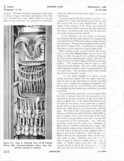
jumpers. All cables should be fabricated on the bench<br />
as shown in figure 2-B before installation in the Cabinet.<br />
Ferrules Navy Typ" -f0670, which are not supplied<br />
by the contractor, are required for fabrication<br />
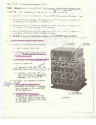
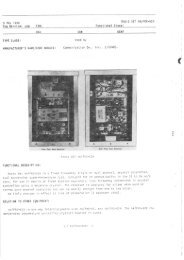
Figure 2-9. Type A, Close-Up View of<br />
Wiring With Connector-Adqpters Novy<br />
491652 lnstqlled in Cobinef<br />
2-10<br />
NAVSHIPS 9rO47<br />
RESTRICTED<br />
INSTAt[ATlf,]hi AND<br />
of the RF cables to bond the outer'rraid ' T::*<br />
interference.<br />
In connecting the RG-f2 /V cable to ute Connt,...f r)i-<br />
Adapters Naq, Type CIA-49I652 conncct them so that<br />
the circuits will ,un in some logical order. For example,<br />
if the antennac of the station are nnmbr red,<br />
the # I antenna should connect to the left hand Jack<br />
Box (when viewed from the front) and the #L position<br />
of the Antenna Selector Switch.<br />
(3) AF wIRING.-All AF wirin,,r is fabricatec<br />
frorn twisted, shielded pairs obtained by stripping the<br />
ottter plastic from TTRS series cable or similar twisted,<br />
shielded pairs. Wiring when completed will look like<br />
that shown in figure 2-L0. Connections are similar to<br />
that shown on the connection diagrarn figure 2-40.<br />
When making up the required internal AF wiring,<br />
bear in mind that sufficient slack must be left in the<br />
wiring to allow the panels to be pulled out through<br />
the front without disturbing the wiring. Note the "lJ"<br />
shape of the laced cable in figure 2-10 which is for this<br />
purpose. This requirement must be kept in mind<br />
when placing the clamps. The entire cable is painted<br />
with fungacide varnish as stated in par agraph 2, b (8)<br />
of section three. The installing activity mtrst furnish<br />
the necessary fungacide varnish.<br />
(q,) AF JACK PANELS.-As shown on the<br />
wiring convention (figure 2-21) the upper and lower<br />
pairs of jacks on the Jack Strip are wired in parallel<br />
and in such a fashion that plugging horizontally into<br />
the top pair breaks the normal circuit; while plugging<br />
horizontally into the bottom pair establishes a parallel<br />
connection.<br />
To accomplish this connection, a piece of #20 AWG<br />
bus wire is soldered from the tip connection of the<br />
top bank to the tip connection of the lower bank as<br />
shown in figure 2-13. In the Signal Distribution Unit,<br />
only !h" tip connection of the patchcord is utilized.<br />
but the body is connected and can be used if required.<br />
Each pair splits between two horizontally adjacent<br />
jacks. The ends of the twisted pairs are fitted with<br />
Thomas and Betts Grounding Ferrules #200-30006 as<br />
shown in figur"e 2-15 to prevernt fraying of the braid.<br />
The shield is not grr.uncled on the jacl Yip end., but<br />
it is grounded on the terminal boa ! .?o(r. Thtrs, the<br />
grounditrg braid and the spade lu5; ;llrrstrated in<br />
figtrre 2-I5 are omittecl in wiring the fa.r:i,. :trips. Skin<br />
off the plastic coating on the conductors frir :.bout L / 4"<br />
and slip a piece of #9 radio qrade spaghetti about I"<br />
long on each of the conductors. Insert the bare ..crrductors<br />
through the appropriate holes, Cotrble l)ac, .,<br />
and so]der in place. Establish some stlrt "f i:o!')r<br />
code to make it easier to visually trace a : r'tic' "-u'<br />
cable. If TTRS-4 cable is used, the r' ;ht ' ',-;d p,rir<br />
RF Cqbinei<br />
Type CIA-<br />
of jacks should be black, the second F,air<br />
third pair red, and the fourth pair greei, I ', :tlyisi,riilt";iNAt