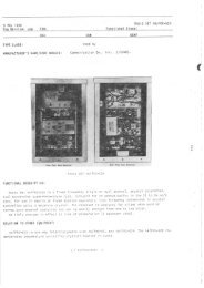
2 Section Porogroph I h(3)(q) able to leave everlr fourth lead, in this case the green lead, as a spare. It should be cut to such a length that it will reach frorn the farthest jack to the farthest terminal in a partictrlar run and then doubled back and laced into the cable. (b) TERN{INAL BOARDS.-There are two methods of mounting the terminal boards as illustrated in figures 2-10 and 2-I4. Wiring is as illustrated. 1. FRONT PANEL MOUNTING (Fisure 9-10 ).-The terminal boards on the equipment as shipped are motrnted on special size B panels AN Typ" I-242/G, which fit into regular rack mountittg space. If the front panel space is not required for some other Figure 2-ll. TyPe A, Close-Up View of Wiring Showing Method of Locing qnd 2-12 NAVSHIPS AF Cqbinet Clqmping 9ro47 RESTRICTED INSTALLATIfi'.d .q!'{n GF*[d flot-{ equipment, this is the most convenient clcll^,cll, \'lr.rittg is as shown in figure 2-10. In clamp'tg tt;,. '',',,irir,l4,, be sure to place the clamps in such o ptrsiricr. ti,, il.e -"th jre boards may be pulled out throtrgh the front , wiring corlnected. 2. SIDE PANEL MOr NTII.IC D't,Q'trr: 2-1ln).-should additional front panel mounting spat' ' be required, the terminal strips may be mounted the side of the Cabinet opposite from the side whicl: carries the convenience outlet strip (right hand looking from the rear). The mountittg is accomplished by drill' ing and tapping appropriate holes in the rear vertical corner angle of the Cabinet. One of the movable vertical channels is installed in such a position that it may be drilled and tapped to support the opposite end of the panel. This type of mounti.tg is possible only if the components mounted on the front panels do not protrude more than 4L,/2 inches beyond the rear of the front panel. 3. WIRINC THE TERMINAL BOARDS.- The terminals on the boards are numbered in pairs. These numbers correspond with the pairs of sim" Y numbered jacks on the jack strips. Figure 2-40 's a typical connection diagram. The actual connections will of necessity be determined by the needs of the individual station. In making the connections on the terminal strip end of the internal wiring, Thomas and Betts Grounding Ferrules #200-30006 or the equivalent are used in all cases. These ferrules are installed as illustrated in figure 2-L5. After the spade lugs are installed on the ends of the conductors, ring out all circuits and clip the spade l.rg rvhich connects to the right hand jack of a particular lair, thus making it possible to maintain polarity. The terminal board illustrated in figure 2-L6 is wired using this method. Solder on a piece of # 14 AWG tinned bus wire as shown in figure 2-L6 and solder the groundittg braids to it. It is not necess ary to ground the panel itself as the paint he.s been omitted around the mountittg screws to make it self groundittg. Remember to leave enough cal,'Ie to allow the terminal boards to be pulled out for servicing with the wiring connected. (c) AF SELECTOR SWITCH WIRING.-Referring to figure L-I7, it can be seell that the spacing between the terminals is very close. Tl ' ends are made up using the Thomas and Betts G,r"ounding Ferrules #200-30006 or equivalent as shown in figure 2-15. The shield is not grounded on this end. l. prcce of #L radio grade spaghetti L/2" long is slipped qvet the grounding ferrule to prevent it from trtalrirtg ':lectrical contact with the terminals, thus causi., ,; a . lrt circuit. A piece of #9 radio grade spa.tahe{tr l" ltlng is then slipped over each conductrr and tlre 1.; *rle lugs which come secured to the terminals are c,,,,:{':. ir t ea,. h frFiK$rhlAt
'{\t ';TJ\LI. ATION AND t )i'Eh, 'i i'..)N NAVSHTPS 9rO47 Section 2 Figure 2-12. AF Jock Ponel Wired Using Thomqs qnd Betts Grounding Ferrules #200-30006 Figure ? ' ll. Close.Up Showing Method of wirins -;;:He Jqcks on Reqr of Jqck Mounting Strips Novy Type CIRIfi {r-l,fr[ RESTRICTED 2-13
- Page 1 and 2: NAYSHIPS 9T.O47 s {t INSTRUCTTON BS
- Page 3 and 4: Effective Poges NAVSHTPS 9rO47 FRON
- Page 5 and 6: Correction Poge NAVSHTPS 9rO47 FRON
- Page 7 and 8: Contents NAVSHIPS 91047 FRONT MATTE
- Page 9 and 10: lllustrotions qnd Tobles NAVSHTPS 9
- Page 11 and 12: Miscellqneous Dotq NAVSHTPS 9rO47 R
- Page 14 and 15: 1 Section NAVSHIPS 91047 t GENERAL
- Page 16 and 17: 1 Section Porogroph I d NAVSHTPS 9r
- Page 18 and 19: 1 Seclion Porogroph 3 q (l) compone
- Page 20 and 21: 1 Section Porogroph 3 q (5) NAVSHTP
- Page 22 and 23: 3q(7) NAVSHIPS 91047 GE \'ERAL DESC
- Page 24 and 25: 1 Section Porogroph 3 q (lI) NAVSHI
- Page 26 and 27: 1 Section Porogrcph 3 s (14) NAVSHI
- Page 28 and 29: 1 Section Porogroph 3 q (18) Figure
- Page 30 and 31: 1 Section Porogroph 4 NAVSHTPS 9rO4
- Page 32 and 33: 1 Section Toble l-2 NAVSHIPS 9rO47
- Page 34 and 35: 1 Section Tqble l-4 TABTE I.4. NAVS
- Page 36 and 37: 1 Section Tqble l -6 TABTE I.6. NAV
- Page 38: 1 Section Tqble l-7 NAVSHIPS 9rO47
- Page 41 and 42: INSTAI:.A,"lOtt An\t" NAVSHIPS 9104
- Page 43 and 44: lN$T'ALt ATION AND CPERA; 'N | , ,i
- Page 45 and 46: :..:,., : iNSTALIAiION AND OPE:iA]
- Page 47 and 48: iNSTAILATION AND NAVSHTPS 9rO47 Sec
- Page 49 and 50: aNSTALId{TION AND c)FElr:r\1'1i1N N
- Page 51: INSTA^II,,f\TION AND OIIEfr ATI'.}N
- Page 55 and 56: I'{STALII=TIT}N AND {)PEItA'i':*)\!
- Page 57 and 58: lf$5TAl I ,*r li'lf,iFtl AND ,Jii[R
- Page 59 and 60: !NSTA[!.A[IONI At"lD C}PERATiEF,I N
- Page 61 and 62: INs TAI,i.ATIt'f.I AND CIPERATIC.f
- Page 63 and 64: INSTAIIAI I'-,$ti jti{D OPERATIGT.'
- Page 65 and 66: INSTAIuATIC,N Ah{t, OPERA.IQII{ iE,
- Page 67 and 68: irugrA[[A?'.]l-l A r-fD OFtftATION
- Page 69 and 70: { AND NAVSHTPS 9rO47 Section 2 Figu
- Page 71 and 72: LAFI'iNr{ AND noN NAVSHIPS 91047 Se
- Page 73 and 74: 'iit ''fr 1 ATION AND toN NAVSHIPS
- Page 75 and 76: I sTAI.I,AYICN F ND )ERAI *rf*l NAV
- Page 77 and 78: INSTATTATION AND OPERATION NAVSHIPS
- Page 79 and 80: D NAVSHIPS 9rO47 Section 2 Figure 2
- Page 81 and 82: NAVSHIPS 91047 Section 2 Figure 2-3
- Page 83 and 84: .LATION AND ,TloN' NAVSHIPS 9rO47 S
- Page 85 and 86: )N AND NAVSHIPS 9rO47 Section 2 Fig
- Page 87 and 88: -l -l NAVSHTPS 91047 Section 2 Figu
- Page 89 and 90: dl I LLATION AND \TION NAVSHIPS 9rO
- Page 91: G J AIIATION AND TATION NAVSHIPS 9r
- Page 94 and 95: Me TNTENANCE NAVSHIPS 9rO47 Section
- Page 96 and 97: MAINTET'IAI-ICE NAVSHIPS 9rO47 Sect
- Page 98 and 99: fr^AINTENANi:E rirther thun rt'pa"i
- Page 100 and 101: MAINTEN"qf*tCE ( f ; If several adj
- Page 103 and 104:
I I I F{ F{ F{ F{ 4 Section Spore P
- Page 105 and 106:
ar l9 ra \v - F F 4 Section A-l ol
- Page 107 and 108:
1 4 Section A-l4f _ E-241C NAVSHIPS
- Page 109 and 110:
F{ vvvv vvv v F{ Fl F{ F{ r-{ F{ v
- Page 111 and 112:
Aal FF Fts .F .- FF FH la \v lv !v
- Page 113 and 114:
l.\ a\ '-\ .F'F F4LvLv dd- ts A\ vv
- Page 115 and 116:
-\ F{ F{ -.{ F{ F{ P{ 4 Section H-l
- Page 117 and 118:
vv F{ Fi aa ^l l-) ^l 6\ 6\ F- Hts
- Page 119 and 120:
vv vvvv vvvv HH 4 Section N-l 06 N-
- Page 121 and 122:
I 4 Section N-l301 N-l503 NAVSHTPS
- Page 123 and 124:
--^ww vvvv vvvv 1 \J \I vv +, +J 4
- Page 125 and 126:
\Jv!/vv a 4 Section P-401B S-20I NA
- Page 127 and 128:
I a^AAA v \-/ \-/ v zh vvvv 4 Secli
- Page 129:
I '! H F{ FL 4 Section NAVSHIPS 910