36 MB pdf download - VIR History
36 MB pdf download - VIR History
36 MB pdf download - VIR History

Create successful ePaper yourself
Turn your PDF publications into a flip-book with our unique Google optimized e-Paper software.
2 Section<br />
Porogroph I h(3)(c)<br />
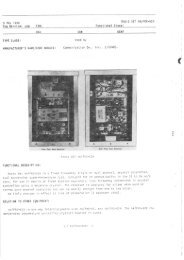
Figure 2-14. Top View Showing Alternqle Method<br />
of Mounting Terminql Boqrds<br />
conductor. These spades are then bent out to about<br />
45o to further lessen the danger of short circtrits. The<br />
individual pairs are then laced together into convenient<br />
size cables and painted with fungicide varnish.<br />
i. EXTERNAL INTERCONNECTINC CABLES.-<br />
It is advisable to complete the internal cabinet wiring<br />
before installittg the external wirittg.<br />
(1) RF WIRING.-The receiver inptrt and miscellaneous<br />
apparatus jacks have been left blank in<br />
figure 2-9 as these connections vary with individual installations.<br />
Connections to the antenna input of the receivers<br />
are made with RG-12/U cable, and the connectors<br />
are installed ' the Signal Distribution Unit<br />
end of cables as sh \^/n in figure 2-8. See the applicable<br />
instruction book for the receivittg equipment for<br />
the type of plug to be installed on the other end of<br />
these cables. The cables are led throtrgh the regular<br />
RF cableways in the "Q" flooring or equivalent of the<br />
station to the proper receivittg equipment (see figure<br />
2-L for a description of the "Q" flooring). The cables<br />
must be clamped with the clamps provided inside the<br />
Signal Distribution Unit in the same manner as the internal<br />
cables illtrstrated in figure 2-9. Keep in mind<br />
that the bending radius of the RG-r2 /rJ cable must be<br />
not less than ten times the diameter of the cables.<br />
Refer to figures 2-37, 2-38, and 2-39 for the external<br />
connections to be made in a typical installation.<br />
NAVSHIPS 9rO47<br />
INSTALI,\TIT: N ANI,<br />
s:r'-.tATloN<br />
(2) OPERATOR'S POSITION.- ,i ' .: standard<br />
operator's position consists of two ,,ji-i,l i'r's rnourrted<br />
so that they may be conveniently coir.^oilecl by c:e<br />
operator. A Control AN Typ" C-443/G is pro'-' ,:',1<br />
for headphone outputs as part of the Signal Dist,.:':if -<br />
tion Unit to enable the operator to guard either: l':' "<br />
ceiver or, by operation of a knob, to guard botl, ,rt<br />
once. The function of this control is covered moro<br />
fully in par agraph 2, e of this section. The installit,g<br />
activity must mount this control on the operator's<br />
table. Alternate methods of mounting the control are<br />
shown on figures 2-31 through 2-<strong>36</strong>. The installirrg<br />
activitv must design and fabricate suitable mounting<br />
brackets for this purpose as none are provided by the<br />
contractor. Wiring of the control is shown on the<br />
interconnecting diagrams figures 2-37, 2-38, and 2-39;<br />
and the schematic figure 2-29.<br />
(3) EXTERNAL AF WIRING.-As explained<br />
above, two receiver output cables go into each Control<br />
AN Typ" C-443/G, while only one cable (TTRS-4) goes<br />
out. Thus there are approximately half as many receiver<br />
output cables which go into the AF cabinet as<br />
there are receivers. An undetermined number of AF<br />
cables go to the loads, the number being dependent<br />
upon the number of speakers, recorders, teletypes, etc.<br />
which are in the station allowance. The receiver output<br />
cables come in on the left hand side of the AF<br />
cabinet of the Signal Distribution Unit and the load<br />
cables go out the right hand side looking from the rear.<br />
Ctrt-outs for these cables are shown in figure 2-2. Remember<br />
that the AF cables are run in the AF cableways<br />
of the "Q" flooring or equivalent cable ducts.<br />
The receiver output cables come up the left hand<br />
side of the cabinet as explained above. There is not<br />
enough space for a single layer of cables, so they must<br />
be clamped in two banks. Arrange the layers so that<br />
the cables which connect to the highest terminal strips<br />
in the Cabinet are on the bottom layer. One set of<br />
clamps hold both lavers of cables.<br />
The load cables go out of the right hand side of the<br />
AF cabinet as explained above. They are stacked in<br />
layers and clamped in exactlv the same manner as the<br />
receiver output cables.<br />
Both the receiver output and the load cables are<br />
TTRS-4 cable. As shown in figures 2-10 and z-ll, the<br />
complete cable is brought in through the cut-out ir<br />
the floor and clamped. The outer plastic covering is<br />
cut off at about the level of the terminal board to whicli<br />
the conductors are to connect. The twisted pairs are<br />
then laced together and formed into a loop as shorn'n<br />
in figure 2-Ll which leads into the rear of the terminal<br />
boards. Connections are then made to the al,[)l'op ;tt€<br />
terminals with spade lugs and Thc'mas ai rd Betts<br />
Grounding Ferrules #200-30006, as :'llc".vr, in figu:c<br />
2-15. The groundittg braid is soldered i: the ,..'.lrirmon<br />
2-1 4<br />
RESTRICTED .3ttl-"ilNAl.