36 MB pdf download - VIR History
36 MB pdf download - VIR History
36 MB pdf download - VIR History

Create successful ePaper yourself
Turn your PDF publications into a flip-book with our unique Google optimized e-Paper software.
GENERAL<br />
DESCRIPTION<br />
NAVSHTPS 9rO47<br />
Section 1<br />
Porogroph3d(5)(o)<br />
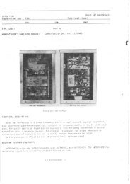
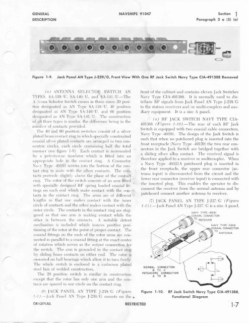
Figure I-9. Jqck PqnelANType J-239/G, FrontViewWith One RF Jqck Switch Novy Type CIA-491388 Removed<br />
(u) ANTtrNNA SEI,ECTOR SWITCH AN<br />
TYPES, SA-139 / U , SA-140 ,/U , and SA-14f /V .-The<br />
A .'crrna Selector Switch cornes in three sizes | 20 position<br />
designated as AN Type SA-IS9./U, 40 position<br />
Cesignated rrs AN Typ" SA-I4}/U, and 60 position<br />
designated as AN Typ" SA-I4I/U. The constrtrction<br />
of all three tvpes is similar, the difference being in the<br />
nunlb:'r' of contacts provided.<br />
The 10 and 60 position srvitches consist of a rillzerr<br />
plated brass contact ring in which specially constructed<br />
coaxial silver plated contacts are arranged in two concentric<br />
circles, each circle containing half the total<br />
ntrrnirer (see figtrre 1-B). Each contact is slrrl'ounded<br />
by a poll'styrene instrlator rvhich is fitted into arl<br />
appropriate hole in the contact ring. A Connector<br />
Nil'i'\' Typ" -49191 screws into thc- bottorn of the contact<br />
ring to rnat€' with the silver contac:ts. The contacts<br />
protrtrcle slightl'v riirove the plane of the contact<br />
ring. The rotor of the switch consists of an arm ftttecl<br />
q<br />
with specially designed RF spring loaded coaxial fittings<br />
on each end which make contact with the colr- ;,<br />
tacts in the contact ring. The arms are of different 'ilengths<br />
so that one rnakes contact rvith the inner<br />
circle of contacts and the clther rnakes contact with the<br />
outer circle. The contacts in the contact ring are staggered<br />
so that one arrn is rnaking contact while the<br />
other is between the contacts. A suitable detent<br />
rnechanism is includecl which insures positive positioning<br />
of the rotor at the point of proper contact. The<br />
coaxial fittings on the encls of the rotor anns are connected<br />
in parallel to a coaxial fitting at the exact center<br />
of rotation which serves as the output connection for<br />
the switch. The arm is grounded to the contact ring<br />
lry sliding brass contacts on either: end. The rotor is<br />
moturted on ball bearings which allow it to turn freely.<br />
The whole switch is enclosed in a cadrnium plated<br />
steel box of welded construction.<br />
The 20 position srvitch is sirnilar in construction<br />
except that the rotor has only one arm and the contacts<br />
al'e spaced in one circle on the contact ring.<br />
(6) IACK PANFTL AN<br />
I-i:) "-- [.rck Panerl AN Ty'p"<br />
oR,!6lliA[<br />
TYPE I-239/C ( Figure<br />
I-239/C rnounts on the r<br />
RESTRICTED<br />
front of the cabinet and cclntains eleven Jack Switches<br />
Navy T,tp" CIA-49IBBB. It is normally used to distribute<br />
IIF signals from Jack Panel AN Typ" I-238/G<br />
to the station receivers and,/ or multi-couplers and auxiliarv<br />
ecluipment. It is a srze A panel.<br />
(C,.) RF JACK SWITCH NAVY TYPE CIA.<br />
49I3BB (Figure 1-10).-The rear of each RF Jack<br />
Switch is eqtripped with trvo coaxial cable connectors,<br />
Navy Typ" -49f91. The design of the Jack Switch is<br />
such that when no patchcord plug is inserted into the<br />
front receptacle (Navy Typ" -19L20) the two rear connectors<br />
in the Jack Switch are bridged together with<br />
a sliding silver alloy contact. The received signal is<br />
therefore applied to a receiver or multicotrpler. When<br />
a Navy Typ" -4912fA patchcord plug is inserted in<br />
the front receptacle, the upper rear connector (antenna<br />
input) is disconnected from the circuit and the<br />
lower rear connector (receiver input) is connected with<br />
the inserted plug. This enables the operator to disconnect<br />
the receiver from the nonnal antenna and by<br />
patchcord connect another antenna to receiver.<br />
(7) IACK PANEL AN TYPE I-237/C (Fisure<br />
1 -11) .-I"ck Panel AN Typ" I-237 / C is a size A panel,<br />
NORMAL CONNECTION<br />
BTOG<br />
PATCHGORD CONNECTION<br />
ATO B<br />
NAVY TYPE- 49I9I<br />
COAXIAL CONNECTOR<br />
Jo RECETvER<br />
NAVY TYPE -49I9I<br />
TO ANTENNA<br />
Figure l-10. RF Jqck Switch Novy Type CIA-491388,<br />
Functionol Diogrqm