36 MB pdf download - VIR History
36 MB pdf download - VIR History
36 MB pdf download - VIR History

You also want an ePaper? Increase the reach of your titles
YUMPU automatically turns print PDFs into web optimized ePapers that Google loves.
3q(7)<br />
NAVSHIPS 91047<br />
GE \'ERAL<br />
DESCRIPT!ON<br />
Figure l-ll.<br />
Jqck Pqnel AN Type J-237/G, FrontView With One Connector AN Type UG-294/U Removed<br />
which mounts orl the front of the cabinet, containing<br />
eleven RF Connectors AN Typ" UG-294/U. The front<br />
or panel ends mate with Navy Typ" -49I2LA patchcord<br />
plugs and are used to patch multicoupler or miscellaneous<br />
sources to the input lines of the station<br />
receivers through Jack Panel AN Typ" I-239/G. The<br />
rear ends mate with Navv Typ" -49190 connectors and<br />
erternal cable from multicoupler outputs or miscellaneou<br />
s sources.<br />
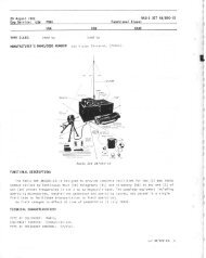
(8) CONTROL AN TYPE C-143/G (figure<br />
1-12).-Control AN T.rzpe C-443/G is the connecting<br />
link betvr,'een the Signal Distribution Unit and the AF<br />
output from two radio receivers at each operator's position<br />
within the station, or any remote position included<br />
in the Distribution Systern. This component which is<br />
ciesigned for mountitrg under the front edge of a<br />
Standard Navy Operator's Table (see figure 2-34) consists<br />
essentially of a three position rotary selector<br />
switch used for selection of either or both receiver outputs<br />
to the operator's phones, a set of toggle switches<br />
for connecting the receiver audio circuits to the Distribution<br />
[-init, and four pairs of phone jacks for the<br />
operator's headset connections. The operator's headset<br />
is normally connected to the set of jacks designated<br />
"SEL" which permits either or both receiver<br />
outptrts to be impressed on the phones by the action of<br />
the three position rotary selector switch. The set of<br />
jacks designated "lJ" may be connected from a utility<br />
line to the operator's position. The jacks marked Receiver<br />
" ^" and Receiver "8" are coltnected in parallel<br />
with the receiver outputs and are used to connect the<br />
operator's headset to each receiver without the use of<br />
the selector switch. The construction of all jacks is<br />
such that headsets equipped with Navy Typ" -49109<br />
single plugs are inserted in the left hand jack, and<br />
those equipped with Navy Typ" -49L242 twin plugs<br />
are inserted in both jacks.<br />
The toggle switches connect the receiver outputs to<br />
the audio lines between Control AN Typ" C-443/C<br />
and the Receiver Otrtput Terminal Boards AN Typ"<br />
I-242/G. With the switches open, the operator has<br />
the receiver outputs available at his phoues, and the<br />
selector switch permits either or both receiver outputs<br />
to be heard.<br />
(9) TERMINAL BOARD ASSE<strong>MB</strong>LY AN TYPE<br />
I-242/ G ( F'igure 1-13 ).-Terminal Board Assembly<br />
RESTRICTED<br />
AN Typ" I-242/G consists of a size B p,tr^e . on the rear<br />
of which four barrier typ" terminal boards mount.<br />
Each is equipped with thirteen double screw type terminals.<br />
The terminal boards are offset from the panel<br />
by brackets to allow space for the connecting internal<br />
AF cables, which are fabricated from modified TTRS<br />
series cable. Terminal designation strips are numbered<br />
consecutively in pairs from 1-13 inclusive on the<br />
two top terminal boards and 14-26 inclusive on the<br />
two bottom terminal boards. For a description of the<br />
wiring, refer to paragraph L, lL (3) of section 2.<br />
(10) JACK MOUNTING STRIP, NAVY TYPE<br />
-491394 ( Fi,gure 1-14) .-The Jack Mounting Strip<br />
Navy Typ" -491394 is a size A panel which includes<br />
mountitrg for 52 Telephone Jacks, Navy Typ" -491395,<br />
arranged in two rows of 26 jacks each. Wiring, which<br />
is installed by the installation activity, is so connected<br />
that horizontally adjacent pairs connect to the two<br />
sides of a single circuit. Only the tips of the twin plug<br />
patchcords make connection. The vertically adjacent<br />
iacks are connected in parallel in such a fashion that<br />
when a patchcord is inserted into the top pair, the<br />
norrnal circuit to the load is broken and a new connection<br />
substituted; but when a patchcord plug is inserted<br />
into the bottom jacks., the normal circuit is unaltered<br />
and the patchcord is then in parallel. Thus, a total of<br />
13 circuits may be connected into any one lack Mounting<br />
Strip.<br />
Figure lr-12. Control AN Type C'443/G, Frcnl' View<br />
QRIGINAT