36 MB pdf download - VIR History
36 MB pdf download - VIR History
36 MB pdf download - VIR History

Create successful ePaper yourself
Turn your PDF publications into a flip-book with our unique Google optimized e-Paper software.
2 Section<br />
Porogroph I i (3)<br />
NAVSHTPS 9rO47<br />
|!lSTfnLt.d\ I' i,f,';'t A,"t{$:,'<br />
f: ('\ j'-<br />
i".+l'iiflr,;<br />
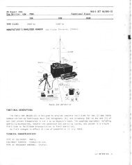
Figure 2-15. Terminol Boord Wired Using Modified TTRS Coble qnd Thomqs ond Belts Grounding Ferrules<br />
#200-30006<br />
ground buss on the terminal board (see figure 2-L6).<br />
Be sure that the loop is made big enough to allow the<br />
terminal board to be pulled through the front for<br />
servicing with the wires connected. Whenever polarity<br />
must be maintained, ring out the circuits and clip<br />
the ltrg on the conductor which connects to the same<br />
terminal as the clipped lrrg in the internal cabinet<br />
wiring.<br />
i. PRIN'IARY POWER CONNECTIONS ( f isure<br />
2-17 ).-The primary power input cable to the cabinets<br />
connects into Switch Panel AN Typ" SA-134 /C<br />
through a knockout in the bottom for L/2 or 3/4 inch<br />
conduit (conduit not furnished). The normal primary<br />
power input is 115 volts AC, 60 cycles. Fuses<br />
required are 15 ampere for convenience and strip outlet<br />
and one ampere capacity for the trouble light circuit.<br />
Supplv of 230 r' 60 cycles may be used if equipment<br />
served within Cabinets is so rated and if 5 amp<br />
fuses are used.<br />
It. INSTALLATION TESTS.<br />
(t) CONTINUITY TESTS.-When the cabinet<br />
wiring is completed and all interconnections made,<br />
each unit should be given a final check before being<br />
put in service. This is to insure that the components<br />
have been correctly installed and that all wiring connections<br />
are complete. A continuity check should be<br />
made on each unit with the volt-ohm-milliammeter or<br />
a portable device for ringing or lighting out circuits.<br />
To check continuitv through a particular wire, refer<br />
to the applicable connection diagram figures 2-37<br />
throtrgh 2-4L and proceed as follows:<br />
( u) Select some starting point on the diagram,<br />
preferably an input.<br />
(b) Mark this point on the diagram and locate<br />
the corresponding point in the equipment.<br />
( c ) Trace the circuit from this point to the next<br />
point where contact can be made such as a terminal<br />
board, switch terminal, etc., and test the continuity.<br />
2-15<br />
RESTRICTED<br />
Mark the test.points and check wires on the diagrarn<br />
to insure that all wires aie checked thoroughly.<br />
( d) Proceed in this manner, marking each<br />
point until all wires are completely checked as indicated<br />
between test points on the diagram.<br />
(e) Draw up a corrected connection diagram<br />
for the particular installation showing actual circuit<br />
markings as installed for use of maintenance men to<br />
permit rapid diagnosis of trouble in the future.<br />
(2) INSULATION TESTS.-After continuity has<br />
been established in all circuits, test insulation resistance<br />
with test equipment provided by BuShips as<br />
part of the system. The resistance of the RF cables to<br />
ground must be approximately 50 megohms or more.<br />
In the AF section, the resistance between conductors<br />
and between the conductors and ground must be at<br />
least five megohms. Replace or repair defective components<br />
as necess ary. Record all values in a suitable<br />
manner and turn them over to the officer-in-charge for<br />
subsequent use by maintenance personnel.<br />
l. AF JUMPER CABLES.-Connections between<br />
the Interconnecting Terminal Boards of the AF section<br />
(see figures 2-22 and 2-23) are made by flexible jrr-pers<br />
fitted with spade lugs so that the connections may<br />
be readily altered to minimize use of patchcords on<br />
front panels. The installing activity should {abrica .e<br />
enough of these jumpers to connect all circuits in the<br />
equipment. The jumpers are made of suitablt, {w irited<br />
pairs fitted with Thomas and Betts Grounding 'rr'errules<br />
#200-30006 and spade lugs on each end installer'<br />
in the manner shown in figure 2-I5. The jumper<br />
should be made long enough to reach between, thc;<br />
most remote terminals of the Interconnectin J 'Ie:r -<br />
minal Boards. Clip the spade lugs on both ends o't:<br />
one of the conductors in each jumper to mr.'.,e it "rutsible<br />
to maintain polarity.<br />
m. MARKINC.-Designation strip;, and i'ard hokiers<br />
are provided on the panels for int:':'r'tion li circuit<br />
OR,iGI?'JA[