36 MB pdf download - VIR History
36 MB pdf download - VIR History
36 MB pdf download - VIR History

You also want an ePaper? Increase the reach of your titles
YUMPU automatically turns print PDFs into web optimized ePapers that Google loves.
2 Section<br />
Porogroph I h(3)(q)<br />
able to leave everlr fourth lead, in this case the green<br />
lead, as a spare. It should be cut to such a length that<br />
it will reach frorn the farthest jack to the farthest terminal<br />
in a partictrlar run and then doubled back and<br />
laced into the cable.<br />
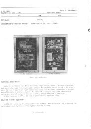
(b) TERN{INAL BOARDS.-There are two<br />
methods of mounting the terminal boards as illustrated<br />
in figures 2-10 and 2-I4. Wiring is as illustrated.<br />
1. FRONT PANEL MOUNTING (Fisure<br />
9-10 ).-The terminal boards on the equipment as<br />
shipped are motrnted on special size B panels AN Typ"<br />
I-242/G, which fit into regular rack mountittg space.<br />
If the front panel space is not required for some other<br />
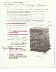
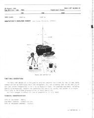
Figure 2-ll. TyPe A, Close-Up View of<br />
Wiring Showing Method of Locing qnd<br />
2-12<br />
NAVSHIPS<br />
AF Cqbinet<br />
Clqmping<br />
9ro47<br />
RESTRICTED<br />
INSTALLATIfi'.d .q!'{n<br />
GF*[d flot-{<br />
equipment, this is the most convenient clcll^,cll, \'lr.rittg<br />
is as shown in figure 2-10. In clamp'tg tt;,. '',',,irir,l4,,<br />
be sure to place the clamps in such o ptrsiricr. ti,, il.e<br />
-"th jre<br />
boards may be pulled out throtrgh the front ,<br />
wiring corlnected.<br />
2. SIDE PANEL MOr NTII.IC D't,Q'trr:<br />
2-1ln).-should additional front panel mounting spat' '<br />
be required, the terminal strips may be mounted<br />
the side of the Cabinet opposite from the side whicl:<br />
carries the convenience outlet strip (right hand looking<br />
from the rear). The mountittg is accomplished by drill'<br />
ing and tapping appropriate holes in the rear vertical<br />
corner angle of the Cabinet. One of the movable vertical<br />
channels is installed in such a position that it may<br />
be drilled and tapped to support the opposite end of<br />
the panel. This type of mounti.tg is possible only if<br />
the components mounted on the front panels do not<br />
protrude more than 4L,/2 inches beyond the rear of<br />
the front panel.<br />
3. WIRINC THE TERMINAL BOARDS.-<br />
The terminals on the boards are numbered in pairs.<br />
These numbers correspond with the pairs of sim" Y<br />
numbered jacks on the jack strips. Figure 2-40 's a<br />
typical connection diagram. The actual connections<br />
will of necessity be determined by the needs of the<br />
individual station.<br />
In making the connections on the terminal strip<br />
end of the internal wiring, Thomas and Betts Grounding<br />
Ferrules #200-30006 or the equivalent are used<br />
in all cases. These ferrules are installed as illustrated<br />
in figure 2-L5. After the spade lugs are installed on<br />
the ends of the conductors, ring out all circuits and<br />
clip the spade l.rg rvhich connects to the right hand<br />
jack of a particular lair, thus making it possible to<br />
maintain polarity. The terminal board illustrated in<br />
figure 2-L6 is wired using this method. Solder on a<br />
piece of # 14 AWG tinned bus wire as shown in figure<br />
2-L6 and solder the groundittg braids to it. It is not<br />
necess ary to ground the panel itself as the paint he.s<br />
been omitted around the mountittg screws to make it<br />
self groundittg. Remember to leave enough cal,'Ie to<br />
allow the terminal boards to be pulled out for servicing<br />
with the wiring connected.<br />
(c) AF SELECTOR SWITCH WIRING.-Referring<br />
to figure L-I7, it can be seell that the spacing<br />
between the terminals is very close. Tl ' ends are<br />
made up using the Thomas and Betts G,r"ounding Ferrules<br />
#200-30006 or equivalent as shown in figure<br />
2-15. The shield is not grounded on this end. l. prcce<br />
of #L radio grade spaghetti L/2" long is slipped qvet<br />
the grounding ferrule to prevent it from trtalrirtg ':lectrical<br />
contact with the terminals, thus causi., ,; a . lrt<br />
circuit. A piece of #9 radio grade spa.tahe{tr l" ltlng<br />
is then slipped over each conductrr and tlre 1.;<br />
*rle lugs<br />
which come secured to the terminals are c,,,,:{':. ir t ea,. h<br />
frFiK$rhlAt