36 MB pdf download - VIR History
36 MB pdf download - VIR History
36 MB pdf download - VIR History

Create successful ePaper yourself
Turn your PDF publications into a flip-book with our unique Google optimized e-Paper software.
2 Section<br />
Porogroph 2 b<br />
NORMAL<br />
CIRCUIT<br />
LOAD<br />
CLEARED<br />
PARAL LEL<br />
PATCHING<br />
LOWER JACKS ]<br />
RIGHT<br />
LEFT<br />
LEFT<br />
RIGHT<br />
MISCELLANEOUS APPARATUS<br />
wlRrNG coNvENTloN LEFT<br />
NORMAL<br />
CIRCUIT<br />
SIGNAL<br />
CLEARED<br />
(7)<br />
RIGHT<br />
LEFT<br />
PARALLEL<br />
PATCHING<br />
LOWER JAGKS<br />
f RIGHT<br />
UPPER JACKS<br />
PANEL<br />
RECEIVER<br />
A F LINE<br />
UPPER JACKS<br />
LOAD CIRCUIT<br />
LINE<br />
Figure 2-21 . Wiring Convention, AF Section<br />
NAVSHTPS 9rO47<br />
INSTA}"LATION AND<br />
OPERATION<br />
For measuring an incoming frequcrrr^.1'.". uurrrlect an RF<br />
patchcord from the RF COUPLIN{.1 l;.i che LM-I5a tr;<br />
the appropriate jack on ]ack PaneJ ,i.l\ "i'Ipe I-2381r;.<br />
To calibrate a receiver, connect an RIr patchcord fl ;:n<br />
the RF COUPLII{G on the LM-I5a to tr.' appropriate<br />
jack Switch on Jack Panel AN Type !-2L'-,,/G.<br />
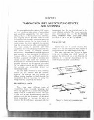
c. OPERATING PROCEDURE AF SPICTION,--<br />
The audio section of the Signal Distributior 'init lrsists<br />
of terminal boards and ]ack Panels sirnilar to a<br />
telephone switchboard connecting the receiver outputs<br />
to the desired loads. Provision is made for testing and<br />
monitoring.<br />
(1) "NORMAL TIIROUGH" OPERATION.-As<br />
in the RF section, "normal through" circuits are provided<br />
so that a receiver may be operated from its normally<br />
connected load without patching. The AF section<br />
differs in that the "normAl through" circuits may<br />
be readily altered by flexible leads between the Interconnecting<br />
Terminal Boards. "Normal through" operation<br />
should be used wherever possible, but it will<br />
probably be necessary to depart from normal procedure<br />
more often than in the RF section.<br />
supervisor to analyze a signal on the monitor receiver<br />
with the test equipment provided.<br />
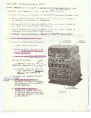
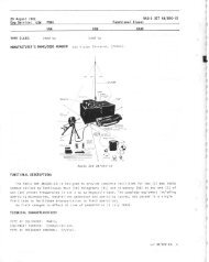
(7) FREQUENCY METER.-AII sizes of the Signal<br />
Distribution Unit include frequency meters which<br />
are furnished by BuShips. The frequency meter may<br />
be used to measure the frequency of a certain specific<br />
signal which is being received on one of the station<br />
antennae or any other RF Signal which is within its<br />
frequency range.<br />
In the Types A and B Units of the Signal Distribution<br />
System, a Frequency Meter Navy Model LR-l is<br />
included (motrnting rack AN Typ" MT-S7L/G only<br />
furnished by contractor). Jack Panel AN Typ"<br />
J-265/G, which is included for connection to the Frequency<br />
Meter, has two jacks which connect by short<br />
patchcords to similar jacks on the Frequency Meter<br />
marked RF OUTPUT. These jacks, in turn, are connected<br />
to jacks on Jack Panel I-237 /C. To calibrate<br />
a receiver, connect an RF patchcord from the appropriate<br />
Jack Switch on Jack Panel AN Typ" I-239/G to<br />
the jack on Jack Panel AN Typ" J-237/C which connects<br />
with the RF OUTPUT on the Frequency Meter.<br />
For more complete information on the use of the LR-l<br />
refer to LR-l Instruction Book (unnumbered).<br />
In the Typ" C Unit of the Signal Distribution Syttem,<br />
a Frecluency N,{eter Navy Model LM-I5a (modified<br />
for rack mountittg) is substituted to save space.<br />
Jack Panel I-265/G is omitted as the Frequency Meter<br />
is close enough to the regular RF jack panels to be<br />
patched in directly. On the LM-15a, there is only one<br />
jack marked RF COLTPLINC rather than two jacks.<br />
RECEIVER OUTP UTS FROM<br />
CONTROLS AN TYPE C.443/G<br />
og g 9 0 g o 9 9<br />
^o (' o<br />
-o o o o o o o o<br />
LOAD CIRGUITS<br />
RECEIVER OUTPUT T. B<br />
AN TYPE J-242/G<br />
RECEIVER OUTPUT JACK PANE L<br />
(JACK MOUNTING STRIP N.T. -<br />
49t394)<br />
INTERC ONNEGTING T B.<br />
AN TYPE J-242/G<br />
FLEXIBLE LEADS<br />
INTERCON N E CTING T. B.<br />
AN TYPE J-242.lG<br />
MISG. APPARATUS JAGK P' NEL<br />
IJACK MOUNTING STRIP<br />
49t394)<br />
MISG. APPARATUS :<br />
AN TYPE J-242/G<br />
Figure 2-22. "Normql Through" Operution, AF<br />
Section<br />
2-22<br />
RESTRICTED ORTGINHL