SMT/THR PCB-COMPONENTS
SMT/THR PCB-COMPONENTS
SMT/THR PCB-COMPONENTS

You also want an ePaper? Increase the reach of your titles
YUMPU automatically turns print PDFs into web optimized ePapers that Google loves.
3 THE <strong>SMT</strong> PROCESS<br />
FOR MODULES WITH <strong>THR</strong> <strong>COMPONENTS</strong><br />
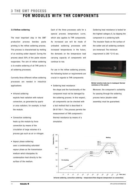
3.5 Reflow soldering<br />
The most important step in the <strong>SMT</strong><br />
production process besides paste<br />
printing is the reflow soldering process.<br />
This process is characterised by melting<br />
of an existing solder deposit. During the<br />
process about 50% of the paste volume<br />
evaporates. The aim of reflow soldering<br />
is to enable soldering of all <strong>THR</strong> joints in<br />
all soldering processes.<br />
Currently three different reflow soldering<br />
processes are needed in industrial<br />
applications:<br />
• Infrared soldering:<br />
exploits heat radiation with natural<br />
convection, as generated by quartz<br />
or area radiators, for example, to heat<br />
the module.<br />
• Convection soldering:<br />
heats up the module by force<br />
convection by means of the<br />
circulation of large volumes of a<br />
Each of the three processes calls for a<br />
special process temperature curve,<br />
which also applies to <strong>THR</strong> components.<br />
As increased use will be made of<br />
unleaded soldering processes with<br />
increased temperatures in the future,<br />
the demands on the temperature load<br />
carrying capacity of components will<br />
continue to rise.<br />
For use in the reflow soldering process,<br />
the following factors or requirements are<br />
crucial in regards to <strong>THR</strong> components:<br />
• Soldering heat resistance:<br />
the shape and the functionality of the<br />
component must not be damaged by<br />
the soldering process. In this respect,<br />
all components can be checked with<br />
a test method that is described in<br />
EN 61760-1. This process permits the<br />
measurement of <strong>THR</strong> component’s<br />
thermal resistance by means of a<br />
simulation.<br />
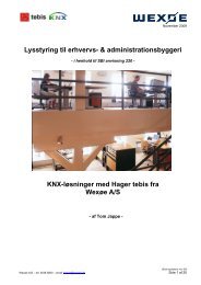
Soldering heat resistance is tested for<br />
the highest category A, by dipping the<br />
component in a soldering bath:<br />
The insulator floats on the surface of<br />
the solder and all soldering contacts<br />
are immersed. The minimum<br />
requirement is 260 °C/10 sec.<br />
Melted isolation body due to inadequat thermal<br />
resistance of the plastic<br />
Moreover, the component's suitability<br />
for passing through the soldering<br />
process twice (double-sided<br />
assembly) must be guaranteed.<br />
process gas such as air or nitrogen.<br />
• Vapour phase soldering:<br />
uses a condensating saturated<br />
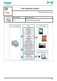
Temperature (°C)<br />
240° C<br />
230° C<br />
215° C<br />
Melting<br />
vapour phase as the transmission<br />
medium which dissipates its<br />
condensation heat directly to the<br />
surface of the medium.<br />
180° C<br />
Pre-heating<br />
160° C<br />
150° C<br />
130° C<br />
Approx. 60sec<br />
> 180° C<br />
Usual<br />
Time (sec)<br />
Infrared soldering, convection soldering – temperature/time diagram (temperature on connection)<br />
14 APPLICATION INFORMATION