SMT/THR PCB-COMPONENTS
SMT/THR PCB-COMPONENTS
SMT/THR PCB-COMPONENTS

Create successful ePaper yourself
Turn your PDF publications into a flip-book with our unique Google optimized e-Paper software.
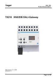
Additional design factors :<br />
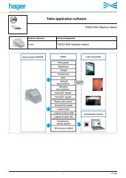
Stencil hole diameter<br />
For a smooth <strong>SMT</strong> production process,<br />
the following factors should also be<br />
observed when designing a module:<br />
• shadow formation in the reflow<br />
oven, caused by high housings of<br />
the <strong>THR</strong> components, can be avoided<br />
by an adequate distance between the<br />
components<br />
• the components' contact faces must<br />
be taken into account to ensure that<br />
the insulator does not come into<br />
contact with the paste<br />
• fixing by glueing may be necessary<br />
if, in the case of double-sided<br />
modules, a <strong>THR</strong> component is placed<br />
on the first placement side<br />
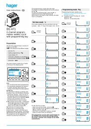
Stencil hole layout assuming adequate degree of paste filling<br />
Stencil hole diameter about<br />
10% smaller than soldering<br />
eyelet diameter<br />
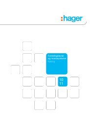
Solutions and recommendations from Weidmüller<br />
In a first draft of the printed circuit board and stencil layout, you can safely work<br />
with the known standard process parameters.<br />
For their SL-<strong>SMT</strong> pin headers with short pins (1.5 mm), Weidmüller suggests the<br />
following <strong>PCB</strong> design:<br />
Placement hole diameter: 1.5 mm<br />
Soldering eyelet diameter: 2.3 mm<br />
Stencil hole diameter: 2.1 mm (assuming adequate degree of paste filling)<br />
Stencil hole diameter: 2.8 mm (if the degree of paste filling is not enough)<br />
Valid for:<br />
<strong>PCB</strong> thickness: 1.5 - 1.6 mm<br />
Stencil thickness: 0.12 - 0.18 mm<br />
APPLICATION INFORMATION 9