SMT/THR PCB-COMPONENTS
SMT/THR PCB-COMPONENTS
SMT/THR PCB-COMPONENTS

Create successful ePaper yourself
Turn your PDF publications into a flip-book with our unique Google optimized e-Paper software.
3 THE <strong>SMT</strong> PROCESS<br />
FOR MODULES WITH <strong>THR</strong> <strong>COMPONENTS</strong><br />
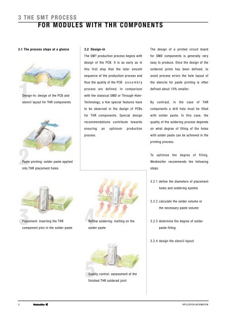
3.1 The process steps at a glance<br />
1Design-In: design of the <strong>PCB</strong> and<br />
stencil layout for <strong>THR</strong> components<br />
3.2 Design-in<br />
The <strong>SMT</strong> production process begins with<br />
design of the <strong>PCB</strong>. It is as early as in<br />
this first step that the later smooth<br />
sequence of the production process and<br />
thus the quality of the <strong>PCB</strong> assembly<br />
process are defined. In comparison<br />
with the classical SMD or Through-Hole-<br />
Technology, a few special features have<br />
to be observed in the design of <strong>PCB</strong>s<br />
for <strong>THR</strong> components. Special design<br />
recommendations contribute towards<br />
ensuring an optimum production<br />
process.<br />
The design of a printed circuit board<br />
for SMD components is generally very<br />
easy to produce. Once the design of the<br />
soldered joints has been defined, to<br />
avoid process errors the hole layout of<br />
the stencils for paste printing is often<br />
defined about 10% smaller.<br />
By contrast, in the case of <strong>THR</strong><br />
components a drill hole must be filled<br />
with solder paste. In this case, the<br />
quality of the soldering process depends<br />
on what degree of filling of the holes<br />
with solder paste can be achieved in the<br />
printing process.<br />
2Paste printing: solder paste applied<br />
into <strong>THR</strong> placement holes<br />
To optimise the degree of filling,<br />
Weidmüller recommends the following<br />
steps:<br />
3.2.1 define the diameters of placement<br />
holes and soldering eyelets<br />
3Placement: inserting the <strong>THR</strong><br />
component pins in the solder paste<br />
4Reflow soldering: melting on the<br />
solder paste<br />
3.2.2 calculate the solder volume or<br />
the necessary paste volume<br />
3.2.3 determine the degree of solder<br />
paste filling<br />
3.2.4 design the stencil layout<br />
5Quality control: assessment of the<br />
finished <strong>THR</strong> soldered joint<br />
6 APPLICATION INFORMATION