5.5 initial diagnostic check: efi - harley-davidson-sweden.se
5.5 initial diagnostic check: efi - harley-davidson-sweden.se
5.5 initial diagnostic check: efi - harley-davidson-sweden.se

Create successful ePaper yourself
Turn your PDF publications into a flip-book with our unique Google optimized e-Paper software.
HOME<br />
NO ECM POWER 5.11<br />
GENERAL<br />
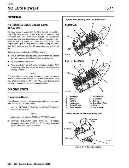
System Fu<strong>se</strong> Block (Under Left Side Cover)<br />
No Spark/No Check Engine Lamp<br />
at Key ON<br />
Constant power is supplied to the ECM through terminal 31.<br />
The ECM turns on when power is applied to terminal 13 of<br />
connector [78]. The ECM goes through an <strong>initial</strong>ization<br />
<strong>se</strong>quence every time power is removed and re-applied to terminal<br />
13. The only visible part of this <strong>se</strong>quence is the <strong>check</strong><br />
engine lamp. Upon starting, the <strong>check</strong> engine lamp will illuminate<br />
for 4 <strong>se</strong>conds and then (if parameters are normal) go<br />
out.<br />
If battery power is ab<strong>se</strong>nt at ECM terminal 31:<br />
●<br />
●<br />
DTCs cannot be cleared. Tool will show them as cleared<br />
but will be pre<strong>se</strong>nt next time ignition key is cycled.<br />
ECM cannot be re-flashed.<br />
FLHR/C/S<br />
9<br />
10<br />
11<br />
12<br />
f2210x8x<br />
1<br />
FLTR, FLHT/C/U<br />
2<br />
8<br />
8 7<br />
5<br />
3<br />
4<br />
●<br />
Vehicle will start but IAC pintle will not re<strong>se</strong>t at key OFF.<br />
Eventually pintle will be out of position causing performance<br />
problems.<br />
NOTE<br />
The key ON <strong>se</strong>quence also activates the idle air control<br />
motor. If power from terminal 31 is disrupted (blown fu<strong>se</strong>,<br />
etc.) always turn the key OFF wait 10 <strong>se</strong>conds then turn the<br />
key ON to re<strong>se</strong>t the motor to the default position.<br />
11<br />
10<br />
9<br />
6<br />
5<br />
4<br />
DIAGNOSTICS<br />
f2204x8x<br />
1<br />
2<br />
3<br />
Diagnostic Notes<br />
The reference numbers below correlate with the circled numbers<br />
on the Test 5.11 flow charts.<br />
1. Connect BREAKOUT BOX (Part No. HD-43876). See 5.7<br />
BREAKOUT BOX: EFI.<br />
1. Headlamp<br />
2. Ignition<br />
3. Lighting<br />
4. Instruments<br />
5. Brakes/Crui<strong>se</strong><br />
6. Radio Memory<br />
7. Radio Power<br />
8. Accessory<br />
9. Battery<br />
10. Brake Light Relay<br />
11. P&A<br />
12. Starter Relay<br />
NOTE<br />
Adapters are not u<strong>se</strong>d on FLTR and FLHT/C/U models.<br />
2. Connect BREAKOUT BOX (Part No. HD-42682)<br />
between connectors [22A] and [22B] using Adapters<br />
(HD-42962) on FLHR/C/S models.<br />
EFI Fu<strong>se</strong> Block (Under Right Side Cover)<br />
Spare<br />
Fuel Pump<br />
EFI System<br />
Relay<br />
ECM Power<br />
f2223x9x<br />
Figure 5-19. Fu<strong>se</strong> Locations<br />
5-30 2004 Touring: Engine Management (EFI)