5.5 initial diagnostic check: efi - harley-davidson-sweden.se
5.5 initial diagnostic check: efi - harley-davidson-sweden.se
5.5 initial diagnostic check: efi - harley-davidson-sweden.se

You also want an ePaper? Increase the reach of your titles
YUMPU automatically turns print PDFs into web optimized ePapers that Google loves.
HOME<br />
SYSTEM RELAY CHECK 5.14<br />
GENERAL<br />
System Relay<br />
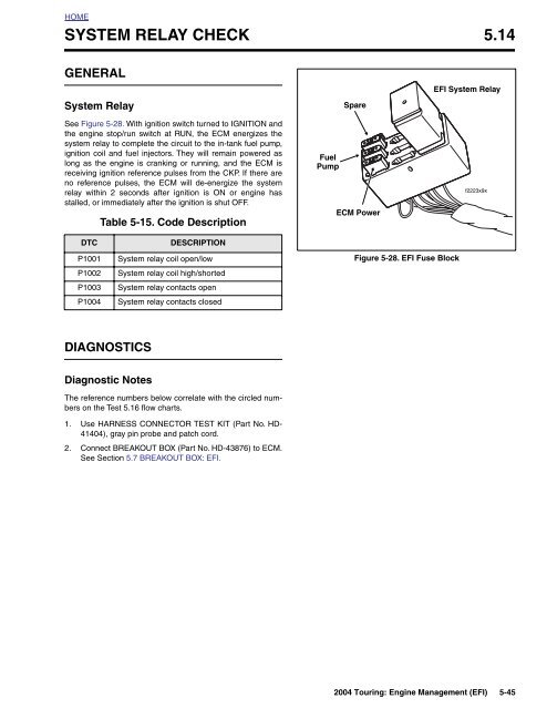
See Figure 5-28. With ignition switch turned to IGNITION and<br />
the engine stop/run switch at RUN, the ECM energizes the<br />
system relay to complete the circuit to the in-tank fuel pump,<br />
ignition coil and fuel injectors. They will remain powered as<br />
long as the engine is cranking or running, and the ECM is<br />
receiving ignition reference pul<strong>se</strong>s from the CKP. If there are<br />
no reference pul<strong>se</strong>s, the ECM will de-energize the system<br />
relay within 2 <strong>se</strong>conds after ignition is ON or engine has<br />
stalled, or immediately after the ignition is shut OFF.<br />
Table 5-15. Code Description<br />
Fuel<br />
Pump<br />
Spare<br />
ECM Power<br />
EFI System Relay<br />
f2223x9x<br />
DTC<br />
P1001<br />
P1002<br />
P1003<br />
P1004<br />
DESCRIPTION<br />
System relay coil open/low<br />
System relay coil high/shorted<br />
System relay contacts open<br />
System relay contacts clo<strong>se</strong>d<br />
Figure 5-28. EFI Fu<strong>se</strong> Block<br />
DIAGNOSTICS<br />
Diagnostic Notes<br />
The reference numbers below correlate with the circled numbers<br />
on the Test 5.16 flow charts.<br />
1. U<strong>se</strong> HARNESS CONNECTOR TEST KIT (Part No. HD-<br />
41404), gray pin probe and patch cord.<br />
2. Connect BREAKOUT BOX (Part No. HD-43876) to ECM.<br />
See Section 5.7 BREAKOUT BOX: EFI.<br />
2004 Touring: Engine Management (EFI) 5-45