5.5 initial diagnostic check: efi - harley-davidson-sweden.se
5.5 initial diagnostic check: efi - harley-davidson-sweden.se
5.5 initial diagnostic check: efi - harley-davidson-sweden.se
Create successful ePaper yourself
Turn your PDF publications into a flip-book with our unique Google optimized e-Paper software.
HOME<br />
INITIAL DIAGNOSTIC CHECK: EFI <strong>5.5</strong><br />
GENERAL<br />
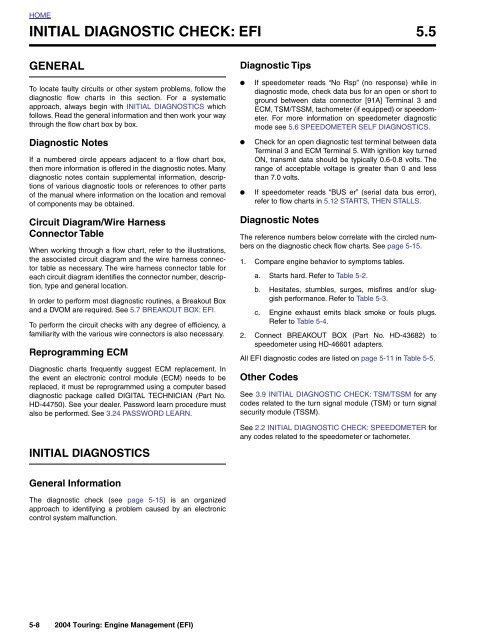
To locate faulty circuits or other system problems, follow the<br />
<strong>diagnostic</strong> flow charts in this <strong>se</strong>ction. For a systematic<br />
approach, always begin with INITIAL DIAGNOSTICS which<br />
follows. Read the general information and then work your way<br />
through the flow chart box by box.<br />
Diagnostic Notes<br />
If a numbered circle appears adjacent to a flow chart box,<br />
then more information is offered in the <strong>diagnostic</strong> notes. Many<br />
<strong>diagnostic</strong> notes contain supplemental information, descriptions<br />
of various <strong>diagnostic</strong> tools or references to other parts<br />
of the manual where information on the location and removal<br />
of components may be obtained.<br />
Circuit Diagram/Wire Harness<br />
Connector Table<br />
When working through a flow chart, refer to the illustrations,<br />
the associated circuit diagram and the wire harness connector<br />
table as necessary. The wire harness connector table for<br />
each circuit diagram identifies the connector number, description,<br />
type and general location.<br />
In order to perform most <strong>diagnostic</strong> routines, a Breakout Box<br />
and a DVOM are required. See 5.7 BREAKOUT BOX: EFI.<br />
To perform the circuit <strong>check</strong>s with any degree of efficiency, a<br />
familiarity with the various wire connectors is also necessary.<br />
Reprogramming ECM<br />
Diagnostic charts frequently suggest ECM replacement. In<br />
the event an electronic control module (ECM) needs to be<br />
replaced, it must be reprogrammed using a computer ba<strong>se</strong>d<br />
<strong>diagnostic</strong> package called DIGITAL TECHNICIAN (Part No.<br />
HD-44750). See your dealer. Password learn procedure must<br />
also be performed. See 3.24 PASSWORD LEARN.<br />
INITIAL DIAGNOSTICS<br />
Diagnostic Tips<br />
●<br />
●<br />
●<br />
If speedometer reads “No Rsp” (no respon<strong>se</strong>) while in<br />
<strong>diagnostic</strong> mode, <strong>check</strong> data bus for an open or short to<br />
ground between data connector [91A] Terminal 3 and<br />
ECM, TSM/TSSM, tachometer (if equipped) or speedometer.<br />
For more information on speedometer <strong>diagnostic</strong><br />
mode <strong>se</strong>e 5.6 SPEEDOMETER SELF DIAGNOSTICS.<br />
Check for an open <strong>diagnostic</strong> test terminal between data<br />
Terminal 3 and ECM Terminal 5. With ignition key turned<br />
ON, transmit data should be typically 0.6-0.8 volts. The<br />
range of acceptable voltage is greater than 0 and less<br />
than 7.0 volts.<br />
If speedometer reads “BUS er” (<strong>se</strong>rial data bus error),<br />
refer to flow charts in 5.12 STARTS, THEN STALLS.<br />
Diagnostic Notes<br />
The reference numbers below correlate with the circled numbers<br />
on the <strong>diagnostic</strong> <strong>check</strong> flow charts. See page 5-15.<br />
1. Compare engine behavior to symptoms tables.<br />
a. Starts hard. Refer to Table 5-2.<br />
b. Hesitates, stumbles, surges, misfires and/or sluggish<br />
performance. Refer to Table 5-3.<br />
c. Engine exhaust emits black smoke or fouls plugs.<br />
Refer to Table 5-4.<br />
2. Connect BREAKOUT BOX (Part No. HD-43682) to<br />
speedometer using HD-46601 adapters.<br />
All EFI <strong>diagnostic</strong> codes are listed on page 5-11 in Table 5-5.<br />
Other Codes<br />
See 3.9 INITIAL DIAGNOSTIC CHECK: TSM/TSSM for any<br />
codes related to the turn signal module (TSM) or turn signal<br />
<strong>se</strong>curity module (TSSM).<br />
See 2.2 INITIAL DIAGNOSTIC CHECK: SPEEDOMETER for<br />
any codes related to the speedometer or tachometer.<br />
General Information<br />
The <strong>diagnostic</strong> <strong>check</strong> (<strong>se</strong>e page 5-15) is an organized<br />
approach to identifying a problem cau<strong>se</strong>d by an electronic<br />
control system malfunction.<br />
5-8 2004 Touring: Engine Management (EFI)


