GPTLR SERIES (2008 Release) - Maxon
GPTLR SERIES (2008 Release) - Maxon
GPTLR SERIES (2008 Release) - Maxon

You also want an ePaper? Increase the reach of your titles
YUMPU automatically turns print PDFs into web optimized ePapers that Google loves.
M-04-06<br />
REV. D<br />
APRIL <strong>2008</strong><br />
INSTALLATION MANUAL<br />
<strong>GPTLR</strong>-25, <strong>GPTLR</strong>-33, <strong>GPTLR</strong>-44, & <strong>GPTLR</strong>-55<br />
© MAXON Lift Corp. <strong>2008</strong>
TABLE OF CONTENTS<br />
<strong>GPTLR</strong> LIFTGATE COMPONENTS ...................................................................................... 5<br />
<strong>GPTLR</strong>-<strong>SERIES</strong> INSTALLATION PARTS BOX ..................................................................... 6<br />
VEHICLE REQUIREMENTS ................................................................................................. 7<br />
STEP 1 - WELD LIFTGATE TO VEHICLE .......................................................................... 12<br />
STEP 2 - RUN POWER CABLE .......................................................................................... 17<br />
STEP 3 - CONNECT POWER CABLE ................................................................................ 18<br />
STEP 4 - INSTALL CONTROL SWITCH ............................................................................. 20<br />
STEP 5 - CHECKING HYDRAULIC FLUID ......................................................................... 22<br />
STEP 6 - CONNECT POWER CABLE TO BATTERY ......................................................... 24<br />
STEP 7 - REMOVE LOCKING BRACKETS ........................................................................ 25<br />
STEP 8 - FINISH WELDING EXTENSION PLATE ............................................................. 29<br />
STEP 9 - ADJUST PLATFORM (IF REQUIRED) ................................................................ 31<br />
STEP 10 - FINISH WELDING LIFTGATE TO VEHICLE ..................................................... 39<br />
STEP 11 - WELD TRUCK BODY TO FRAME (TRUCKS ONLY) ........................................ 40<br />
STEP 12 - ADJUST OPENER (IF REQUIRED) .................................................................. 41<br />
STEP 13 - BOLT ON STOP BLOCK .................................................................................... 44<br />
STEP 14 - ADJUST UNDERRIDE (IF REQUIRED) ............................................................ 45<br />
STEP 15 - ATTACH DECALS .............................................................................................. 50<br />
STEP 16 - ATTACH NONSKID & SAFETY STRIPING ........................................................ 52<br />
STEP 17 - VEHICLE TAILLIGHT POSITIONING (IF REQUIRED) ...................................... 53<br />
LIFTGATES WITH STANDARD ICC BUMPER ................................................. 53<br />
LIFTGATES WITH STANDARD AND OPTIONAL UNDERRIDE ....................... 54<br />
OVAL LIGHT BRACKETS .................................................................................. 55<br />
TOUCHUP PAINT ............................................................................................................... 56
SYSTEM DIAGRAMS ......................................................................................................... 57<br />
PUMP & MOTOR SOLENOID OPERATION (GRAVITY DOWN) ........................................ 57<br />
PUMP & MOTOR SOLENOID OPERATION (POWER DOWN) .......................................... 58<br />
HYDRAULIC SCHEMATIC (GRAVITY DOWN) ................................................................... 59<br />
HYDRAULIC SCHEMATIC (POWER DOWN) .................................................................... 60<br />
ELECTRICAL SCHEMATIC (GRAVITY DOWN) ................................................................. 61<br />
ELECTRICAL SCHEMATIC (POWER DOWN) ................................................................... 62<br />
OPTIONS ............................................................................................................................ 63<br />
RECOMMENDED LIFTGATE POWER CONFIGURATION ................................................ 63
Comply with the following WARNINGS while installing Liftgates. See Operation Manual<br />
for operating safety requirements.<br />
!<br />
WARNING<br />
• Read and understand the instructions in this Installation Manual before installing Liftgate.<br />
• Before operating the Liftgate, read and understand the operating instructions in Operation<br />
Manual.<br />
• Comply with all WARNING and instruction decals attached to the Liftgate.<br />
• Keep decals clean and legible. If decals are illegible or missing, replace them. Free replacement<br />
decals are available from <strong>Maxon</strong> Customer Service.<br />
• Consider the safety and location of bystanders and location of nearby objects when operating the<br />
Liftgate. Stand to one side of the platform while operating the Liftgate.<br />
• Do not allow untrained persons to operate the Liftgate.<br />
• Do not stand, or allow obstructions, under the platform when lowering the Liftgate. Be sure your<br />
feet are clear of the Liftgate.<br />
• Keep fingers, hands, arms, legs, and feet clear of moving Liftgate parts (and platform<br />
edges) when operating the Liftgate.<br />
• Correctly stow platform when not in use. Extended platforms could create a hazard for<br />
people and vehicles passing by.<br />
• Make sure vehicle battery power is disconnected while installing Liftgate. Connect vehicle<br />
battery power to the Liftgate only when installation is complete or as required in the installation<br />
instructions.<br />
• Wear appropriate safety equipment such as protective eyeglasses, faceshield and clothing while<br />
performing maintenance on the Liftgate and handling the battery. Debris from drilling and contact<br />
with battery acid may injure unprotected eyes and skin.<br />
• Be careful working by an automotive type battery. Make sure the work area is well ventilated and<br />
there are no fl ames or sparks near the battery. Never lay objects on the battery that can short the<br />
terminals together. If battery acid gets in your eyes, immediately seek fi rst aid. If acid gets on your<br />
skin, immediately wash it off with soap and water.<br />
• If an emergency situation arises (vehicle or Liftgate) while operating the Liftgate, release the control<br />
toggle switch to stop the Liftgate.<br />
• A correctly installed Liftgate operates smoothly and reasonably quiet. The only noticeable noise<br />
during operation comes from the pump unit while the platform is raised and lowered. Listen for<br />
scraping, grating and binding noises and correct the problem before continuing to operate Liftgate.<br />
11921 Slauson Ave. Santa Fe Springs, CA. 90670 (800) 227-4116 FAX (888) 771-7713<br />
• If it is necessary to stand on the platform while operating the Liftgate, keep your feet and any<br />
objects clear of the inboard edge of the platform. Your feet or objects on the platform can become<br />
trapped between the platform and the Liftgate extension plate.<br />
• Never perform unauthorized modifi cations on the Liftgate. Modifi cations may result in early failure<br />
of the Liftgate and may create hazards for Liftgate operators and maintainers.<br />
• Recommended practices for welding on steel parts are contained in the current AWS (American<br />
Welding Society) D1.1 Structural Welding Code - Steel. Damage to Liftgate and/or vehicle, and<br />
personal injury could result from welds that are done incorrectly.<br />
4
<strong>GPTLR</strong> LIFTGATE COMPONENTS<br />
CAUTION<br />
!<br />
Unpacking the Liftgate on unlevel surface may allow heavy components to slide off<br />
when shipping bands are cut. Injury and equipment damage could result. Before<br />
the shipping bands are cut, put Liftgate on level surface that will support 1500 lbs.<br />
When unpacking the Liftgate, remove heavy components carefully to avoid injury<br />
and damage.<br />
NOTE: Make sure you have all components and parts before you start installing Liftgate.<br />
Compare parts in the part box and each kit box with packing list enclosed in each<br />
box. If parts and components are missing or incorrect call:<br />
<strong>Maxon</strong> Customer Service<br />
Call (800) 227-4116 or<br />
Send e-mail to cservice@maxonlift.com<br />
LIFTGATE<br />
<strong>GPTLR</strong> COMPONENTS<br />
FIG. 5-1<br />
PARTS BOX<br />
11921 Slauson Ave. Santa Fe Springs, CA. 90670 (800) 227-4116 FAX (888) 771-7713<br />
5
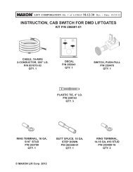
<strong>GPTLR</strong>-<strong>SERIES</strong> INSTALLATION PARTS BOX<br />
ITEM DESCRIPTION QTY. PART NO.<br />
1 FRAME CLIP, 1/2” X 1-3/8” 7 050079<br />
2 COPPER LUG, #2 GA, 5/16” CLOSED END 1 906497-02<br />
MOLDED SWITCH ASSY (GRAVITY DOWN) 1 267959-01<br />
3<br />
MOLDED SWITCH ASSY (POWER DOWN) 1 264951-04<br />
4 FUSED POWER CABLE, 200 AMP, 38’ LG. 1 264422<br />
5 DECAL & MANUAL KIT 1<br />
A. INSTALLATION MANUAL 1 M-04-06<br />
B. OPERATION MANUAL 1 M-04-05<br />
C. MAINTENANCE MANUAL 1 M-04-04<br />
D. WARRANTY CARD 1 M-78-78<br />
E. CUSTOMER SURVEY FORM 1 M-94-04<br />
F. DECALS, NONSKID & SAFETY TAPE<br />
6 CLAMP, #10 RUBBER LOOM 2 801681<br />
7 SELF-TAPPING SCREW, #10-24 X 1” LG. 4 900057-5<br />
8 SHIM, PLATFORM ADJUSTMENT 1/16” 2 281166-01<br />
9 SHIM, PLATFORM ADJUSTMENT 1/8” 2 281166-02<br />
10 STOP BLOCK 1 281673-01<br />
11 CAP SCREW, 1/2”-13 X 2-1/2” LG. 2 900035-7<br />
12 LOCK NUT, 1/2”-13 2 901010<br />
13 FLAT WASHER, 1/2” 2 902000-16<br />
TABLE 6-1<br />
281101-01 (<strong>GPTLR</strong>-25)<br />
281101-02 (<strong>GPTLR</strong>-33)<br />
281124-01 (<strong>GPTLR</strong>-44)<br />
281124-02 (<strong>GPTLR</strong>-55)<br />
REFER TO PAGES FOR<br />
DECALS, NONSKID &<br />
SAFETY TAPE IN THIS<br />
MANUAL<br />
11921 Slauson Ave. Santa Fe Springs, CA. 90670 (800) 227-4116 FAX (888) 771-7713<br />
6
VEHICLE REQUIREMENTS<br />
NOTE: BODY maximum and minimum operating bed height:<br />
For <strong>GPTLR</strong>-25, <strong>GPTLR</strong>-33, <strong>GPTLR</strong>-44, & <strong>GPTLR</strong>-55 with standard platform:<br />
Maximum height is 55” (Unloaded). Minimum height is 44” (Loaded).<br />
On vehicle bodies equipped with swing open doors, the extension plate<br />
and vehicle body must be modifi ed to install this Liftgate.<br />
NOTE: Make sure vehicle is parked on level ground while preparing vehicle and<br />
installing Liftgate.<br />
NOTE: Dimensions are provided as reference for fi tting Liftgate to vehicle body.<br />
1. Check for correct clearances (FIGS. 7-1 and 7-2) on vehicle to prevent interference<br />
between vehicle and Liftgate. Refer to<br />
FIGS. 8-1, 9-1, and 9-2 for additional<br />
34-3/16”<br />
clearances and dimensions.<br />
55” MAX. BED HEIGHT (UNLOADED)<br />
44” MIN. BED HEIGHT (LOADED)<br />
23-5/8”<br />
25-5/8”<br />
26-3/8” MAX.<br />
15-3/8” MIN.<br />
<strong>GPTLR</strong>-25 & -33 LIFTGATE CLEARANCE DIMENSIONS (FOR REFERENCE)<br />
FIG. 7-1<br />
36”<br />
27”<br />
21-3/4”<br />
11921 Slauson Ave. Santa Fe Springs, CA. 90670 (800) 227-4116 FAX (888) 771-7713<br />
24-1/2”<br />
55” MAX. BED HEIGHT (UNLOADED)<br />
44” MIN. BED HEIGHT (LOADED)<br />
22-7/8”<br />
24-7/16” MAX.<br />
13-7/16” MIN.<br />
<strong>GPTLR</strong>-44 & -55 LIFTGATE CLEARANCE DIMENSIONS (FOR REFERENCE)<br />
FIG. 7-2<br />
7
VEHICLE REQUIREMENTS - Continued<br />
LIFT ARM<br />
BODY<br />
CORNER POST<br />
BODY FLOOR<br />
(REFERENCE)<br />
5-5/8” (<strong>GPTLR</strong>-44/-55)<br />
6-1/8” (<strong>GPTLR</strong>-25/-33)<br />
VEHICLE BODY CORNER POST CLEARANCE (FOR REFERENCE)<br />
FIG. 8-1<br />
11921 Slauson Ave. Santa Fe Springs, CA. 90670 (800) 227-4116 FAX (888) 771-7713<br />
8
VEHICLE REQUIREMENTS - Continued<br />
96”<br />
79”<br />
1/2” 3-17/32” (<strong>GPTLR</strong>-25 & -33)<br />
1/2”<br />
4-7/16” (<strong>GPTLR</strong>-44 & -55)<br />
<strong>GPTLR</strong> EXTENSION PLATE DIMENSIONS FOR 96” WIDE BODY<br />
FIG. 9-1<br />
102”<br />
85”<br />
1/2” 1/2”<br />
3-17/32” (<strong>GPTLR</strong>-25 & -33)<br />
4-7/16” (<strong>GPTLR</strong>-44 & -55)<br />
<strong>GPTLR</strong> EXTENSION PLATE DIMENSIONS FOR 102” WIDE BODY<br />
FIG. 9-2<br />
11921 Slauson Ave. Santa Fe Springs, CA. 90670 (800) 227-4116 FAX (888) 771-7713<br />
9
VEHICLE REQUIREMENTS - Continued<br />
2. Fit the Liftgate to vehicle body by cutting<br />
vehicle frame as shown in FIG. 10-1.<br />
11”<br />
5”<br />
REAR SILL<br />
CAUTION<br />
• To prevent aluminum platform from being damaged, make sure vehicle frame<br />
is cut correctly and rear sills are modified if over 5” in height (<strong>GPTLR</strong>-25 &<br />
<strong>GPTLR</strong>-33) or 6” in height (<strong>GPTLR</strong>-44 & <strong>GPTLR</strong>-55). If the cutouts are incorrect,<br />
platform may hit vehicle frame or underbody when stowing the Liftgate.<br />
The bottom of the platform may also hit the sill.<br />
• Installer is responsible for ensuring that vehicle body and frame modifications<br />
do not adversely affect the integrity of the body and frame.<br />
NOTE: The dimensions, shown in the illustration below, are maximums except as<br />
indicated.<br />
NOTE: The platform cutout area shown below applies to trucks and trailers.<br />
NOTE: Refer to the platform clearance cutout area in FIGS. 10-1 and 11-1. Remove<br />
any part of the rear sill that protrudes into this area.<br />
BODY FLOOR<br />
LONG SILL<br />
BODY CROSS<br />
MEMBERS<br />
PLATFORM CLEARANCE CUTOUT AREA<br />
(WITHIN DASHED LINES)<br />
WOODEN SPACER<br />
TRUCK FRAME<br />
11921 Slauson Ave. Santa Fe Springs, CA. 90670 (800) 227-4116 FAX (888) 771-7713<br />
26-1/4”<br />
VEHICLE FRAME CUT FOR <strong>GPTLR</strong>-25 & <strong>GPTLR</strong>-33<br />
FIG. 10-1<br />
10
VEHICLE REQUIREMENTS - Continued<br />
REAR SILL<br />
13”<br />
6”<br />
25-1/4”<br />
BODY FLOOR<br />
LONG SILL<br />
BODY CROSS<br />
MEMBERS<br />
PLATFORM CLEARANCE CUTOUT AREA<br />
(WITHIN DASHED LINES)<br />
WOODEN SPACER<br />
TRUCK FRAME<br />
VEHICLE FRAME CUT FOR <strong>GPTLR</strong>-44 & <strong>GPTLR</strong>-55<br />
FIG. 11-1<br />
11921 Slauson Ave. Santa Fe Springs, CA. 90670 (800) 227-4116 FAX (888) 771-7713<br />
11
STEP 1 - WELD LIFTGATE TO VEHICLE<br />
1. Clamp Liftgate to forklift as shown in FIG. 12-1A. For <strong>GPTLR</strong>-25 and <strong>GPTLR</strong>-33<br />
Liftgates equipped with ICC bumper, place a piece of wood between the ICC bumper<br />
and forks on the forklift for additional support as shown in FIG. 12-1C.<br />
VEHICLE<br />
BODY<br />
LIFTGATE<br />
CLAMP<br />
WARNING<br />
Keep Liftgate clamped to forklift until Liftgate is welded (or bolted if required)<br />
to vehicle body. Liftgate may be damaged and create a hazard for the installer<br />
if it falls off the forklift.<br />
NOTE: To install Liftgate correctly, you must park the vehicle on level ground and follow<br />
the instructions in this manual.<br />
FRAME<br />
LEVEL SURFACE<br />
FIG. 12-1B<br />
!<br />
NOTE: This procedure contains the recommended method for lifting and supporting<br />
the Liftgate during installation. Other methods, such as hoisting the Liftgate,<br />
may be used if careful shop practices are employed.<br />
FIG. 12-1A<br />
ICC BUMPER<br />
11921 Slauson Ave. Santa Fe Springs, CA. 90670 (800) 227-4116 FAX (888) 771-7713<br />
MAINFRAME<br />
(REF)<br />
2-1/2”<br />
FORKS<br />
(ONE SHOWN)<br />
12<br />
WOOD<br />
FIG. 12-1C<br />
2. Use forklift to center the Liftgate in position on the back of the vehicle body and frame<br />
(FIG. 12-1A). If necessary, have 1 person operate the forklift and 1 other person<br />
check alignment of Liftgate and vehicle.
STEP 1 - WELD LIFTGATE TO VEHICLE - Continued<br />
3. Make sure the extension plate is butted<br />
against vehicle body (FIG. 13-1A). Extension<br />
plate (diamond plate surface) must<br />
be level with the ground and fl ush with fl oor<br />
of vehicle body (FIGS. 13-1A & 13-<br />
1B). Position levels in 2 places on extension<br />
plate (FIGS. 13-2A & 13-2B) to<br />
show when extension plate is level with<br />
the ground.<br />
LEVEL SURFACE<br />
FIG. 13-2B<br />
EXTENSION PLATE<br />
(DIAMOND PLATE<br />
SURFACE)<br />
LEVEL SURFACE<br />
FIG. 13-1B<br />
VEHICLE BODY<br />
FLOOR<br />
SIDE VIEW OF EXTENSION PLATE AND<br />
TRUCK BODY (FORKLIFT NOT SHOWN)<br />
FIG. 13-1A<br />
1”<br />
1”<br />
POSITIONING LEVELS ON EXTENSION PLATE<br />
FIG. 13-2A<br />
11921 Slauson Ave. Santa Fe Springs, CA. 90670 (800) 227-4116 FAX (888) 771-7713<br />
13
STEP 1 - WELD LIFTGATE TO VEHICLE - Continued<br />
4. Unbolt the RH side mounting<br />
plate from the fl at on the main<br />
frame (FIG. 14-1). Repeat for<br />
LH side mounting plate. Make<br />
sure Liftgate stays centered on<br />
vehicle body. Reposition both<br />
mounting plates against vehicle<br />
frame (FIG. 15-1).<br />
5. Remove the split loom from RH<br />
side mounting plate (FIG. 14-<br />
1). Repeat for LH side mounting<br />
plate. Save the split loom to<br />
reinstall.<br />
WARNING<br />
!<br />
Liftgate is shipped from factory with mounting plates bolted to the main frame.<br />
Weld the mounting plates as shown in illustrations before opertaing Liftgate.<br />
CAUTION<br />
Prevent damage to hydraulic hoses. Before welding next to hydraulic hoses,<br />
protect with heat-resistant cover.<br />
CAUTION<br />
When using electrical welder to weld on mounting plates, make sure the welder<br />
ground lead is connected directly to the mounting plate, as close as possible<br />
to the place being welded. Failure to comply can result in damaged cylinders<br />
and electrical parts.<br />
VEHICLE FRAME<br />
(TYPICAL TRUCK<br />
FRAME SHOWN)<br />
MOUNTING<br />
PLATE<br />
MAIN FRAME<br />
(CUT-AWAY VIEW)<br />
SPLIT LOOM<br />
LOCK NUT<br />
CAP SCREW<br />
FLAT<br />
UNBOLTING MOUNTING PLATE<br />
(RH SIDE SHOWN)<br />
FIG. 14-1<br />
11921 Slauson Ave. Santa Fe Springs, CA. 90670 (800) 227-4116 FAX (888) 771-7713<br />
14
STEP 1 - WELD LIFTGATE TO VEHICLE - Continued<br />
CAUTION<br />
To protect the original paint system, a 3” wide area of paint must<br />
be removed from all sides of the weld area before welding.<br />
NOTE: Weld both mounting<br />
plates to vehicle<br />
frame before welding<br />
mounting plates<br />
to main frame.<br />
6. Clamp both mounting plates<br />
to outboard side of vehicle<br />
frame. Weld each mounting<br />
plate to vehicle frame as<br />
shown in FIG. 15-1. Next,<br />
weld both mounting plates<br />
to main frame (FIG. 15-1).<br />
Remove clamps.<br />
VEHICLE FRAME<br />
(TYPICAL TRUCK<br />
FRAME SHOWN)<br />
2” LG. 4 PLACES<br />
(TYPICAL - RH & LH<br />
MOUNTING PLATES)<br />
1/4”<br />
MOUNTING<br />
PLATE<br />
MAIN FRAME<br />
1/4”<br />
(CUT-AWAY VIEW)<br />
FLAT (REF)<br />
WELD TO VEHICLE FRAME AND MAIN FRAME<br />
(RH SIDE SHOWN)<br />
FIG. 15-1<br />
11921 Slauson Ave. Santa Fe Springs, CA. 90670 (800) 227-4116 FAX (888) 771-7713<br />
15
STEP 1 - WELD LIFTGATE TO VEHICLE - Continued<br />
7. Weld the top of extension plate to vehicle body sill as shown in FIG. 16-1.<br />
2” LG<br />
EQUALLY SPACED BE-<br />
TWEEN 5” LG. WELDS<br />
1/4”<br />
CAUTION<br />
When using electrical welder to weld on extension plate, make sure the welder<br />
ground lead is connected directly to the extension plate, as close as possible<br />
to the place being welded. Failure to comply can result in damaged cylinders<br />
and electrical parts.<br />
NOTE: While welding extension plate to vehicle body sill, make sure the diamond<br />
plate surface on the extension plate stays fl ush with the sill.<br />
1/4”<br />
5” LG, 3 PLACES<br />
CENTER OVER WIDTH OF<br />
3 TUBES<br />
EXTENSION PLATE WELDS - VIEWED FROM ABOVE<br />
(FORKLIFT NOT SHOWN)<br />
FIG. 16-1<br />
11921 Slauson Ave. Santa Fe Springs, CA. 90670 (800) 227-4116 FAX (888) 771-7713<br />
16
STEP 2 - RUN POWER CABLE<br />
Never route an energized wire. Make sure the vehicle battery is disconnected.<br />
Always route electrical wires clear of moving parts, brake lines, sharp edges and<br />
exhaust systems. Avoid making sharp bends in wiring. Attach securely. If drilling<br />
is necessary, first check behind the drilling surface so you do not damage any fuel<br />
lines, vent lines, brake lines or wires.<br />
Clip fused power cable to vehicle chassis, with fuse nearest the vehicle battery, as shown<br />
in FIG. 17-1. Keep enough cable near the battery to reach the positive terminal without<br />
straining cable (after connection). Run cable to pump box on Liftgate.<br />
200 AMP FUSE<br />
18” - 24”<br />
SPACING<br />
!<br />
CABLE<br />
CLIPS<br />
CAUTION<br />
VEHICLE FRAME<br />
(TRUCK FRAME SHOWN)<br />
FRONT OF VEHICLE<br />
CHARGE LINE<br />
(TO PUMP BOX)<br />
11921 Slauson Ave. Santa Fe Springs, CA. 90670 (800) 227-4116 FAX (888) 771-7713<br />
REAR OF VEHICLE<br />
SHORTEST<br />
CABLE END<br />
TERMINAL LUG<br />
(TO VEHICLE BATTERY)<br />
FIG. 17-1<br />
17
STEP 3 - CONNECT POWER CABLE<br />
1. Unbolt the pump cover as shown in FIG. 18-1.<br />
NUTS<br />
(2 PLACES)<br />
FLAT WASHERS<br />
(2 PLACES)<br />
POWER UNIT<br />
(REF)<br />
FIG. 18-1<br />
PUMP COVER<br />
HOLDER FLATS<br />
(2 PLACES)<br />
BOLTS<br />
(2 PLACES)<br />
11921 Slauson Ave. Santa Fe Springs, CA. 90670 (800) 227-4116 FAX (888) 771-7713<br />
18
STEP 3 - CONNECT POWER CABLE - Continued<br />
NOTE: Electrical lines must be run into pump box through sealing grommets<br />
(FIG. 19-3). To ensure a good seal on hydraulic & electrical<br />
lines, never cut the sealing grommets.<br />
2. Run fused power cable through grommet<br />
on pump mounting plate (FIG. 19-3).<br />
3. On the bare wire end of fused power<br />
cable, keep enough length to attach<br />
copper terminal lug and reach starter<br />
solenoid without putting tension on<br />
cable (after connection) (FIG. 19-1).<br />
Measure (if needed) and then cut<br />
excess cable from bare wire end of<br />
cable. Put heatshrink tubing (parts<br />
box) (FIG. 19-1) on the end of the<br />
cable (leave room for terminal lug).<br />
Crimp copper terminal lug (from parts<br />
box) on the fused power cable and<br />
shrink the heatshrink tubing (FIG. 19-2).<br />
NOTE: MAXON recommends using dielectric<br />
grease on all electrical connections.<br />
4. Remove hex nut and lock washer from<br />
battery terminal post on the starter solenoid.<br />
Connect the fused power cable<br />
to the starter solenoid as shown in<br />
FIG. 19-3. Reinstall and tighten lock<br />
washer and hex nut. Torque hex nut to<br />
95 lbs.-in.<br />
FUSED<br />
POWER<br />
CABLE<br />
MOTOR<br />
SOLENOID<br />
COPPER TERMINAL LUG<br />
HEATSHRINK TUBING<br />
(P/N 253316-04)<br />
FUSED POWER CABLE<br />
(BARE WIRE END)<br />
PLACING TERMINAL LUG & HEATSHRINK<br />
TUBING ON FUSED POWER CABLE<br />
FIG. 19-1<br />
TYPICAL FUSED POWER CABLE WITH<br />
TERMINAL LUG INSTALLED<br />
FIG. 19-2<br />
GROMMET<br />
PUMP MOUNTING<br />
PLATE<br />
LOCK<br />
WASHER<br />
HEX<br />
NUT<br />
11921 Slauson Ave. Santa Fe Springs, CA. 90670 (800) 227-4116 FAX (888) 771-7713<br />
BATTERY<br />
TERMINAL POST<br />
TYPICAL FUSED POWER CABLE CONNECTION<br />
(GRAVITY DOWN PUMP SHOWN)<br />
FIG. 19-3<br />
19
STEP 4 - INSTALL CONTROL SWITCH<br />
1. Drill one 3/4“ hole and two #21–size holes in the vertical<br />
post on curb side of vehicle body as shown in FIG. 20-<br />
1A. Use template shown in FIG. 20-1B.<br />
VEHICLE BODY<br />
VERTICAL POST<br />
(CURB SIDE)<br />
1-3/4”<br />
7/8”<br />
HOLE DRILLING TEMPLATE<br />
FIG. 20-1B<br />
NOTE: Electrical lines must be run into<br />
pump box through sealing<br />
grommets (FIG. 20-2). To<br />
ensure a good seal on the electrical<br />
lines, never cut the sealing<br />
grommets.<br />
2. Cut tie strap on coiled wiring harness<br />
(FIG. 20-2). Pull the wiring harness<br />
through grommet on the pump<br />
mounting plate (FIG. 20-2).<br />
TIE<br />
STRAPS<br />
WIRING<br />
HARNESS<br />
RECOMMENDED POSITION FOR<br />
CONTROL SWITCH<br />
FIG. 20-1A<br />
GROMMET<br />
18”<br />
PUMP<br />
MOUNTING<br />
PLATE<br />
11921 Slauson Ave. Santa Fe Springs, CA. 90670 (800) 227-4116 FAX (888) 771-7713<br />
FIG. 20-2<br />
20
STEP 4 - INSTALL CONTROL SWITCH - Continued<br />
NOTE: MAXON recommends using dielectric grease on all electrical connections.<br />
3. Run wiring harness under<br />
vehicle body (see dashed<br />
line - FIG. 21-1) and<br />
up through inside of vertical<br />
post. Next, pull control<br />
switch wiring harness out<br />
the 3/4“ hole drilled in vertical<br />
post (FIG. 21-1).<br />
Connect the control switch<br />
wiring to the wiring harness<br />
as shown in FIG. 21-2.<br />
Push extended wiring back<br />
into the ¾” hole in the vertical<br />
post until control switch<br />
touches the post. Attach<br />
the control switch to vertical<br />
post with 2 self-tapping<br />
screws (FIG. 21-2).<br />
DECAL<br />
(SEE DECALS PAGE)<br />
CONTROL SWITCH<br />
3/4” HOLE VEHICLE BODY<br />
VERTICAL POST<br />
ROUTING CONTROL SWITCH WIRING<br />
FIG. 21-1<br />
BLACK<br />
WHITE<br />
BLACK<br />
WHITE<br />
GREEN<br />
11921 Slauson Ave. Santa Fe Springs, CA. 90670 (800) 227-4116 FAX (888) 771-7713<br />
SCREW,<br />
SELF-TAPPING<br />
GREEN<br />
RED<br />
(POWER DOWN<br />
VERSION ONLY)<br />
CONTROL SWITCH WIRING CONNECTIONS<br />
FIG. 21-2<br />
21
STEP 5 - CHECKING HYDRAULIC FLUID<br />
1. Unbolt and remove pump cover<br />
(FIG. 22-1).<br />
2. Check the hydraulic fl uid level in<br />
reservoir as follows. With Liftgate<br />
stowed, or platform at vehicle bed<br />
height, level should be as shown in<br />
FIG. 22-2.<br />
3. If needed, add fl uid to the reservoir as follows.<br />
Pull out (no threads) fi ller cap (FIG.<br />
22-2). Fill the reservoir with hydraulic fl uid<br />
to level shown in FIG. 22-2. Reinstall fi ller<br />
cap (FIG. 22-2).<br />
CAUTION<br />
Pump cover must be correctly secured<br />
to prevent it from becoming<br />
a hazard. To secure pump cover,<br />
the long side of the holder flats<br />
must butt against pump cover as<br />
shown in the illustration.<br />
CAUTION<br />
Keep dirt, water and other contaminants from entering the hydraulic system.<br />
Before opening the hydraulic fluid reservoir filler cap, drain plug and hydraulic<br />
lines, clean up contaminants that can get in the openings. Also, protect the<br />
openings from accidental contamination.<br />
NOTE: Use correct grade of hydraulic fl uid for your location.<br />
+50 to +120 Degrees F - Grade ISO 32<br />
Below + 70 Degrees F - Grade ISO 15 or MIL-H-5606<br />
See TABLES 23-1 & 23-2 for recommended brands.<br />
NUTS<br />
(2 PLACES)<br />
FLAT WASHERS<br />
(2 PLACES)<br />
POWER UNIT<br />
(REF)<br />
LONGER SIDE OF<br />
HOLDER FLATS<br />
BUTT AGAINST<br />
COVER<br />
PUMP COVER<br />
BOLTS<br />
(2 PLACES)<br />
UNBOLTING / BOLTING PUMP COVER<br />
FIG. 22-1<br />
FILLER<br />
CAP<br />
RESERVOIR<br />
11921 Slauson Ave. Santa Fe Springs, CA. 90670 (800) 227-4116 FAX (888) 771-7713<br />
4. Bolt on the pump cover as shown in<br />
FIG. 22-1. Torque the 5/16”-18 cover<br />
bolts from 10 to 14 lbs.-ft.<br />
2”<br />
POWER UNIT FLUID LEVEL<br />
FIG. 22-2<br />
22
STEP 5 - CHECKING HYDRAULIC FLUID<br />
- Continued<br />
RECOMMENDED<br />
BRANDS<br />
ISO 32 HYDRAULIC OIL<br />
TABLE 23-1<br />
TABLE 23-2<br />
PART NUMBER<br />
AMSOIL<br />
AWH-05<br />
CHEVRON HIPERSYN 32<br />
KENDALL<br />
GOLDEN MV<br />
SHELL TELLUS T-32<br />
EXXON UNIVIS N-32<br />
MOBIL<br />
DTE-13M, DTE-24,<br />
HYDRAULIC OIL-13<br />
ISO 15 OR MIL-H-5606 HYDRAULIC OIL<br />
RECOMMENDED<br />
BRANDS<br />
PART NUMBER<br />
AMSOIL<br />
AWF-05<br />
CHEVRON<br />
FLUID A, AW-MV-15<br />
KENDALL<br />
GLACIAL BLU<br />
SHELL TELLUS T-15<br />
EXXON<br />
UNIVIS HVI-13<br />
MOBIL<br />
DTE-11M<br />
ROSEMEAD THS FLUID 17111<br />
11921 Slauson Ave. Santa Fe Springs, CA. 90670 (800) 227-4116 FAX (888) 771-7713<br />
23
STEP 6 - CONNECT POWER CABLE TO BATTERY<br />
NOTE: MAXON recommends using dielectric grease on all electrical connections.<br />
Remove nut from positive (+) battery<br />
terminal connector. Connect power<br />
cable to the positive (+) battery terminal<br />
connector (FIG. 24-1). Reinstall<br />
and tighten nut.<br />
NUT<br />
POSITIVE (+) BATTERY<br />
TERMINAL<br />
CONNECTING POWER CABLE<br />
FIG. 24-1<br />
FUSED POWER<br />
CABLE<br />
BOLT<br />
11921 Slauson Ave. Santa Fe Springs, CA. 90670 (800) 227-4116 FAX (888) 771-7713<br />
24
STEP 7 - REMOVE LOCKING BRACKETS<br />
1. Push the control switch to RAISE position<br />
to moderately pressurize hydraulic<br />
system. Remove tack weld from installation<br />
bracket (FIG. 25-1B). Next, unbolt<br />
installation bracket (FIG. 25-1B) from<br />
RH side of extension plate (FIG. 25-<br />
1A). Repeat for LH side.<br />
WARNING<br />
!<br />
To prevent possible injury, never work in the area under the platform. Get access<br />
to the locking angle from the back of the Liftgate.<br />
NOTE: To operate Liftgate, locking bracket must be removed.<br />
2. Remove clamps from forklift and<br />
Liftgate. If wood supports were<br />
used between forklift and ICC<br />
bumper, remove the supports.<br />
Back out forklift (FIG. 25-2).<br />
FIG. 25-1A<br />
FLAT<br />
WASHER<br />
INSTALLATION<br />
BRACKET<br />
NUT<br />
FIG. 25-1B<br />
TOP OF<br />
EXTENSION<br />
PLATE<br />
TACK<br />
WELD<br />
11921 Slauson Ave. Santa Fe Springs, CA. 90670 (800) 227-4116 FAX (888) 771-7713<br />
25<br />
FIG. 25-2
STEP 7 - REMOVE LOCKING BRACKETS - Continued<br />
3. Remove the fl at welded between each<br />
lift arm and extension plate (FIG. 26-1).<br />
Repeat for LH side of Liftgate.<br />
4. Lower the Liftgate to ground level. Remove<br />
both installation brackets. Keep both<br />
brackets in case Liftgate needs to be repositioned<br />
(FIGS. 26-2A & 26-2B).<br />
FLAT<br />
(2 PLACES)<br />
EXTENSION<br />
PLATE<br />
LIFT ARM<br />
REMOVING TACK WELD<br />
(RH SIDE OF LIFTGATE SHOWN)<br />
FIG. 26-1<br />
FIG. 26-2A<br />
11921 Slauson Ave. Santa Fe Springs, CA. 90670 (800) 227-4116 FAX (888) 771-7713<br />
FIG. 26-2B<br />
26
STEP 7 - REMOVE LOCKING BRACKETS - Continued<br />
5. Unfold platform and fl ipover (FIG. 27- 1).<br />
CAUTION<br />
To prevent damage to Liftgate,<br />
the locking bracket on each cylinder<br />
must be removed before operating<br />
Liftgate.<br />
6. Unbolt the locking brackets from<br />
both cylinders (FIG. 27-2).<br />
CAP NUT<br />
LOCKING<br />
BRACKET<br />
BOLT<br />
CAP NUT<br />
CYLINDER<br />
FIG. 27-1<br />
BOLT<br />
LOCKING<br />
BRACKET<br />
11921 Slauson Ave. Santa Fe Springs, CA. 90670 (800) 227-4116 FAX (888) 771-7713<br />
CYLINDER<br />
FIG. 27-2<br />
27
STEP 7 - REMOVE LOCKING BRACKETS - Continued<br />
7. Raise the Liftgate to vehicle<br />
bed height. Check if extension<br />
plate interferes with<br />
lifting arm (FIG. 28-1).<br />
8. Lower the Liftgate to ground<br />
level (FIG. 28-2A). Cut off<br />
the interfering edge on the<br />
extension plate so it is even<br />
with the bottom of extension<br />
plate (FIG. 28-2B). Repeat<br />
for LH side of extension<br />
plate.<br />
INTERFERING<br />
EDGE<br />
EXTENSION PLATE<br />
(BOTTOM EDGE)<br />
FIG. 28-2B<br />
LIFT ARM<br />
FIG. 28-1<br />
VEHICLE BODY<br />
EXTENSION<br />
PLATE<br />
11921 Slauson Ave. Santa Fe Springs, CA. 90670 (800) 227-4116 FAX (888) 771-7713<br />
PLATFORM AT GROUND LEVEL<br />
(RH SIDE SHOWN)<br />
FIG. 28-2A<br />
28
STEP 8 - FINISH WELDING EXTENSION PLATE<br />
CAUTION<br />
When using electrical welder to weld on extension plate, make sure the welder<br />
ground lead is connected directly to the extension plate, as close as possible<br />
to the place being welded. Failure to comply can result in damaged cylinders<br />
and electrical parts.<br />
1. RAISE the platform to bed<br />
level under moderate hydraulic<br />
pressure (FIG. 29-1).<br />
2. Support the main<br />
frame with pallet jack<br />
(FIG. 29-1).<br />
3. Clamp the shackles to<br />
extension plate (FIG.<br />
29-1).<br />
4. Weld the top of extension<br />
plate to vehicle body sill as<br />
shown in FIG. 29-2.<br />
SHACKLE<br />
(NOT SHOWN)<br />
PALLET JACK<br />
CLAMP<br />
(2 PLACES)<br />
1/4”<br />
EXTENSION<br />
PLATE<br />
STURDY CRATE<br />
SUPPORTING PLATFORM & MAIN FRAME<br />
(<strong>GPTLR</strong>-25 SHOWN)<br />
FIG. 29-1<br />
CAUTION<br />
To protect the original paint system, a 3” wide area of paint must<br />
be removed from all sides of the weld area before welding.<br />
TYP 2 PLACES<br />
1/4”<br />
MAIN<br />
FRAME<br />
5” LG, 2 PLACES<br />
1/4”<br />
TYP<br />
2 PLACES<br />
11921 Slauson Ave. Santa Fe Springs, CA. 90670 (800) 227-4116 FAX (888) 771-7713<br />
EXTENSION PLATE WELDS - VIEWED FROM ABOVE<br />
(FORKLIFT NOT SHOWN)<br />
FIG. 29-2<br />
29
STEP 8 - FINISH WELDING EXTENSION PLATE<br />
- Continued<br />
5. Weld the bottom of extension plate to vehicle body sill as<br />
shown in FIG. 30-1.<br />
SILL<br />
(PART OF<br />
VEHICLE BODY)<br />
2” LG, 6 PLACES<br />
1/4”<br />
1” GAP<br />
1” GAP<br />
1” GAP<br />
1/4”<br />
DO THESE WELDS 1ST<br />
TO PREVENT EXTENSION<br />
PLATE FROM TWISTING.<br />
7 PLACES, MAKE 1”<br />
GAP WHERE SHOWN<br />
EXTENSION PLATE WELDS - VIEWED FROM UNDERNEATH<br />
(PLATFORM NOT SHOWN)<br />
FIG. 30-1<br />
11921 Slauson Ave. Santa Fe Springs, CA. 90670 (800) 227-4116 FAX (888) 771-7713<br />
30
STEP 9 - ADJUST PLATFORM (IF REQUIRED)<br />
NOTE: In most cases, if Liftgate is installed<br />
according to the instructions in this<br />
manual, platform will not require adjustment.<br />
Use the following instructions to<br />
check the platform. Adjust the platform<br />
only if required.<br />
NOTE: Before doing the following procedure,<br />
make sure vehicle is still parked on<br />
level ground.<br />
1. RAISE platform to bed height. Check<br />
the platform as follows. Inboard edge<br />
on top of platform must be no more<br />
than 1/4” from diamond plate surface on<br />
top of extension plate (FIGS. 31-1A<br />
& 31-1B). The maximum allowable<br />
horizontal gap between inboard edge<br />
of platform and adjacent edge of extension<br />
plate is 1/4” (FIGS. 31-1A &<br />
31-1C). LOWER platform to ground<br />
level. Shackles and tip of fl ipover should<br />
touch the ground at the same time (FIG.<br />
31-2). Tip of fl ipover must not be<br />
higher than 1/4” above the ground. If all<br />
indications are correct (FIGS. 31-1A,<br />
31-1B, 31-1C, & 31-2), Liftgate is<br />
installed correctly and no adjustment is<br />
needed. If the tip of fl ipover is too high<br />
above the ground, if shackles are off<br />
the ground, or if there is too much gap<br />
between platform and extension plate,<br />
continue doing this procedure.<br />
NOTE: If the shackles do not touch the ground<br />
(see FIG. 27-1), do instruction 2. If<br />
the tip of the fl ipover is more than 1/4”<br />
above the ground (see FIG. 31-2),<br />
skip instructions 2 - 5 and do instruction<br />
6. If there is too much vertical<br />
space (FIG. 31-1B) or horizontal<br />
space (FIG. 31-1C) between platform<br />
and extension plate, start with instruction<br />
7 to remove and reinstall Liftgate.<br />
PLATFORM<br />
1/4”<br />
(MAX.)<br />
1/4” MAX.<br />
EXTENSION<br />
PLATE<br />
1/4” MAX.<br />
PLATFORM<br />
HORIZONTAL GAP<br />
FIG. 31-1C<br />
VERTICAL GAP<br />
FIG. 31-1B<br />
PLATFORM AT<br />
BED LEVEL<br />
FIG. 31-1A<br />
TIP OF FLIPOVER<br />
EXTENSION<br />
PLATE<br />
PLATFORM & SHACKLES<br />
TOUCH GROUND<br />
FIG. 31-2<br />
11921 Slauson Ave. Santa Fe Springs, CA. 90670 (800) 227-4116 FAX (888) 771-7713<br />
31
STEP 9 - ADJUST PLATFORM (IF REQUIRED)<br />
- Continued<br />
2. Make sure platform is still at ground level. If the shackles<br />
are not touching the ground, measure and compare<br />
distance “A” (FIG. 32-1) with TABLE 32-1 to<br />
determine the correct shim.<br />
RAISE TIP OF<br />
FLIPOVER<br />
THIS DISTANCE<br />
“A”<br />
REQUIRED SHIM<br />
THICKNESS<br />
TABLE 32-1<br />
WELD<br />
SIZE<br />
“W”<br />
1” 1/16” 1/32”<br />
2” 1/8” 1/16”<br />
3. Fold the fl ipover and platform. Then, raise the<br />
platform to position shown in FIG. 32-2A.<br />
CAUTION<br />
To protect the original paint system, a<br />
3” wide area of paint must be removed<br />
from all sides of the weld area before<br />
welding.<br />
CAUTION<br />
When using electrical welder to weld on<br />
pin, make sure the welder ground lead<br />
is connected directly to the pin, as close<br />
as possible to the place being welded.<br />
Failure to comply can result in damaged<br />
cylinders and electrical parts.<br />
4. Use TABLE 32-1 to select the correct<br />
size shim and refer to TABLE 32-1<br />
for the correct shim to get from the<br />
parts box. Weld shim to pin as shown<br />
in FIG. 32-2B.<br />
SHIM<br />
(TABLE 32-1)<br />
“W”<br />
(TABLE 32-1)<br />
“A”<br />
(TABLE 32-1)<br />
SHACKLES DO NOT TOUCH<br />
GROUND<br />
FIG. 32-1<br />
FIG. 32-2A<br />
SHACKLE<br />
11921 Slauson Ave. Santa Fe Springs, CA. 90670 (800) 227-4116 FAX (888) 771-7713<br />
PIN<br />
FIG. 32-2B<br />
32
STEP 9 - ADJUST PLATFORM (IF REQUIRED)<br />
- Continued<br />
5. Lower platform to the ground. Unfold platform<br />
and fl ipover. RAISE the platform to bed<br />
height, then LOWER it to the ground. The<br />
tip of fl ipover and shackle should touch the<br />
ground as shown in FIG. 33-1. Tip of fl i-<br />
pover must not be higher than 1/4” above the<br />
ground.<br />
NOTE: For an aluminum platform & fl ipover<br />
equipped with retention ramp, 2” of<br />
ground clearance is acceptable at the<br />
tip of fl ipover.<br />
6. If the tip of fl ipover is more than 1/4” above the<br />
ground (FIG. 33-2), note the distance “B”<br />
above ground level. See the exception in the<br />
NOTE above. Distance “B” will be used for adjusting<br />
the platform later in this procedure.<br />
“B”<br />
1/4”<br />
(MAX.)<br />
TIP OF FLIPOVER<br />
PLATFORM & SHACKLES<br />
TOUCH GROUND<br />
FIG. 33-1<br />
FIG. 33-2<br />
11921 Slauson Ave. Santa Fe Springs, CA. 90670 (800) 227-4116 FAX (888) 771-7713<br />
33
STEP 9 - ADJUST PLATFORM (IF REQUIRED)<br />
- Continued<br />
7. Reinstall locking brackets on<br />
both cylinders (FIG. 34- 1).<br />
Bolt each locking bracket in<br />
place.<br />
CAP NUT<br />
LOCKING<br />
BRACKET<br />
8. Review the WARNING page at<br />
the front of this manual before<br />
continuing this procedure. Stay<br />
clear of moving Liftgate parts.<br />
9. RAISE platform to position<br />
just below extension plate<br />
(see FIG. 34-2A). Place<br />
an installation bracket on<br />
the spring pin on the RH<br />
side of platform (FIG. 34-<br />
2B) and on the spring pin<br />
on the LH side of platform.<br />
INSTALLATION<br />
BRACKET<br />
PLATFORM<br />
BOLT<br />
CYLINDER<br />
LOCKING<br />
BRACKET<br />
SPRING PIN<br />
INSTALLATION BRACKET<br />
(RH SIDE SHOWN)<br />
FIG. 34-2B<br />
CAP NUT<br />
BOLT<br />
REINSTALLING LOCKING BRACKETS<br />
FIG. 34-1<br />
CYLINDER<br />
11921 Slauson Ave. Santa Fe Springs, CA. 90670 (800) 227-4116 FAX (888) 771-7713<br />
FIG. 34-2A<br />
34
STEP 9 - ADJUST PLATFORM (IF REQUIRED)<br />
- Continued<br />
10. Carefully RAISE the platform to vehicle<br />
bed height. Make sure threaded<br />
stud on each installation bracket<br />
comes up through hole in extension<br />
plate (FIG. 35-1). Bolt the installation<br />
bracket (FIG. 35-1) to extension<br />
plate. Torque nut from 39 to<br />
59 lbs.-ft. Repeat for bolting and<br />
torquing the installation bracket on<br />
the LH side.<br />
11. Disconnect power from Liftgate by<br />
removing nut from positive (+) battery<br />
terminal connector and disconnect<br />
power cable (FIG. 35-2).<br />
Reinstall nut on positive (+) battery<br />
terminal connector.<br />
EXTENSION<br />
PLATE<br />
INSTALLATION<br />
BRACKET<br />
NUT<br />
INSTALLATION BRACKET<br />
(RH SIDE SHOWN)<br />
FIG. 35-1<br />
! WARNING<br />
To prevent accidental personal injury and equipment damage, make sure<br />
power is disconnected from Liftgate while installing parts.<br />
NUT<br />
THREADED<br />
STUD<br />
POSITIVE (+) BATTERY<br />
TERMINAL<br />
FLAT<br />
WASHER<br />
FUSED POWER<br />
CABLE<br />
BOLT<br />
11921 Slauson Ave. Santa Fe Springs, CA. 90670 (800) 227-4116 FAX (888) 771-7713<br />
DISCONNECTING BATTERY<br />
FIG. 35-2<br />
35
STEP 9 - ADJUST PLATFORM (IF REQUIRED)<br />
- Continued<br />
12. Support the Liftgate under main<br />
frame with a fl oor jack.<br />
13. Measure distance “C” from the<br />
tip of the fl ipover to ground level<br />
(FIG. 36-1). Next, subtract<br />
the distance “B” measured<br />
in instruction 6. The result is<br />
distance “D” for the platform<br />
adjustment (FIG. 36-3). For<br />
example, if you measured 50”<br />
for “C” and 1” for “B”, the<br />
calculated distance “D” for the<br />
platform adjustment is 49”.<br />
14. Remove welds from RH side<br />
and LH side mounting plates<br />
(FIG. 36-2).<br />
15. Raise or lower the fl oor<br />
jack to adjust distance “D”<br />
between tip of fl ipover and<br />
ground level (FIG. 36-3).<br />
Use the distance “D” calculated<br />
in instruction 13.<br />
“C”<br />
LIFTGATE CLEARANCE DIMENSIONS<br />
FIG. 36-1<br />
VEHICLE FRAME<br />
(TYPICAL TRUCK<br />
FRAME SHOWN)<br />
REMOVE WELDS<br />
REMOVING WELDS FROM MOUNTING PLATE<br />
(RH SIDE SHOWN)<br />
FIG. 36-2<br />
“D”<br />
MAIN FRAME<br />
(CUT-AWAY VIEW)<br />
MOUNTING<br />
PLATE<br />
11921 Slauson Ave. Santa Fe Springs, CA. 90670 (800) 227-4116 FAX (888) 771-7713<br />
LIFTGATE CLEARANCE DIMENSIONS<br />
FIG. 36-3<br />
36
STEP 9 - ADJUST PLATFORM (IF REQUIRED)<br />
- Continued<br />
16. Clamp the RH side<br />
and LH side mounting<br />
plates to vehicle frame.<br />
Weld the mounting<br />
plates to vehicle frame<br />
as shown in FIG. 37-<br />
1. Remove clamps.<br />
CAUTION<br />
When using electrical welder to weld on mounting plates, make sure the<br />
welder ground lead is connected directly to the mounting plate, as close as<br />
possible to the place being welded. Failure to comply can result in damaged<br />
cylinders and electrical parts.<br />
CAUTION<br />
Prevent damaged hydraulic hoses. Before welding next to hydraulic hoses,<br />
protect the hoses with a heat-resistant cover.<br />
CAUTION<br />
To protect the original paint system, a 3” wide area of paint must<br />
be removed from all sides of the weld area before welding.<br />
17. Connect power to Liftgate by removing<br />
nut from positive (+) battery<br />
terminal connector and connect<br />
power cable (FIG. 37-2). Reinstall<br />
and tighten nut on positive<br />
(+) battery terminal connector.<br />
VEHICLE FRAME<br />
(TYPICAL TRUCK<br />
FRAME SHOWN)<br />
2” LG. 4 PLACES<br />
(TYPICAL - RH & LH<br />
MOUNTING PLATES)<br />
1/4”<br />
MAIN FRAME<br />
(CUT-AWAY VIEW)<br />
MOUNTING<br />
PLATE<br />
WELD TO VEHICLE FRAME AND MAIN FRAME<br />
(RH SIDE SHOWN)<br />
FIG. 37-1<br />
POSITIVE (+) BATTERY<br />
TERMINAL<br />
FUSED POWER<br />
CABLE<br />
BOLT<br />
11921 Slauson Ave. Santa Fe Springs, CA. 90670 (800) 227-4116 FAX (888) 771-7713<br />
NUT<br />
18. Lower the fl oor jack and move it<br />
away from the Liftgate.<br />
RECONNECTING BATTERY<br />
FIG. 37-2<br />
37
STEP 9 - ADJUST PLATFORM (IF REQUIRED)<br />
- Continued<br />
19. Unbolt the installation brackets<br />
(FIG. 38-1) from RH side and<br />
LH side of extension plate.<br />
20. LOWER the Liftgate to ground<br />
level (FIG. 38- 2A). Remove<br />
the installation brackets from<br />
RH side and LH side of platform<br />
(FIG. 38- 2B).<br />
CAP NUT<br />
INSTALLATION<br />
BRACKET<br />
LOCKING<br />
BRACKET<br />
EXTENSION<br />
PLATE<br />
THREADED<br />
STUD<br />
INSTALLATION<br />
BRACKET<br />
BOLT<br />
CYLINDER<br />
REMOVING LOCKING BRACKETS<br />
FIG. 38-2A<br />
NUT FLAT<br />
WASHER<br />
INSTALLATION BRACKET<br />
(RH SIDE SHOWN)<br />
FIG. 38-1<br />
CAP NUT<br />
LOCKING<br />
BRACKET<br />
BOLT<br />
CYLINDER<br />
INSTALLATION<br />
BRACKET<br />
11921 Slauson Ave. Santa Fe Springs, CA. 90670 (800) 227-4116 FAX (888) 771-7713<br />
21. Unbolt the locking brackets from<br />
both cylinders (FIG. 38- 2A). Remove<br />
the locking brackets.<br />
REMOVING INSTALLATION<br />
BRACKET (RH SIDE SHOWN)<br />
FIG. 38-2B<br />
38
STEP 10 - FINISH WELDING LIFTGATE TO VEHICLE<br />
1. Weld the mounting<br />
plates to vehicle frame<br />
as shown in FIG. 39-1.<br />
2. Reinstall the split looms on<br />
RH side and LH side mounting<br />
plates (FIG. 39-2).<br />
VEHICLE FRAME<br />
(TYPICAL TRUCK<br />
FRAME SHOWN)<br />
TYPICAL - RH & LH<br />
MOUNTING PLATES<br />
!<br />
CAUTION<br />
When using electrical welder to weld on mounting plates, make sure the<br />
welder ground lead is connected directly to the mounting plate, as close as<br />
possible to the place being welded. Failure to comply can result in damaged<br />
cylinders and electrical parts.<br />
CAUTION<br />
Prevent damage to hydraulic hoses. Before welding next to hydraulic hoses,<br />
protect the hoses with a heat-resistant cover.<br />
CAUTION<br />
To protect the original paint system, a 3” wide area of paint must<br />
be removed from all sides of the weld area before welding.<br />
1/4”<br />
MOUNTING<br />
PLATE<br />
WELD TO VEHICLE FRAME (RH SIDE SHOWN)<br />
FIG. 39-1<br />
CAUTION<br />
To prevent injury and damaged parts, let mounting plate cool off from welding<br />
before reinstalling split loom.<br />
11921 Slauson Ave. Santa Fe Springs, CA. 90670 (800) 227-4116 FAX (888) 771-7713<br />
SPLIT<br />
LOOM<br />
MOUNTING<br />
PLATE<br />
REINSTALLING SPLIT LOOM (RH SIDE SHOWN)<br />
FIG. 39-2<br />
39
STEP 11 - WELD TRUCK BODY TO FRAME<br />
(TRUCKS ONLY)<br />
1. Fabricate two fl ats, from<br />
1/4” thick x 4” wide steel,<br />
that will fi t in the area on<br />
the truck frame shown in<br />
FIG. 40-1.<br />
2. Weld fl at to the truck frame<br />
and the C-channel on the<br />
RH side of truck body as<br />
shown in FIG. 40-1. Repeat<br />
for the LH side of the<br />
truck body.<br />
CAUTION<br />
TRUCK BODY<br />
C-CHANNEL<br />
2 PLACES<br />
AS MUCH AS POSSIBLE<br />
(TYPICAL - RH & LH SIDES<br />
OF TRUCK BODY)<br />
CAUTION<br />
When using electrical welder to weld flats on truck frame, make sure the<br />
welder ground lead is connected directly to the flat, as close as possible to<br />
the place being welded. Failure to comply can result in damaged cylinders and<br />
electrical parts.<br />
To prevent truck body from moving out of position, weld the C-channels on<br />
each side of truck body to truck frame.<br />
CAUTION<br />
1/4”<br />
FLAT<br />
TRUCK FRAME<br />
WELDING TRUCK BODY TO FRAME<br />
(RH SIDE SHOWN)<br />
FIG. 40-1<br />
To protect the original paint system, a 3” wide area of paint must<br />
be removed from all sides of the weld area before welding.<br />
11921 Slauson Ave. Santa Fe Springs, CA. 90670 (800) 227-4116 FAX (888) 771-7713<br />
40
STEP 12 - ADJUST OPENER (IF REQUIRED)<br />
NOTE: The platform must always stow and unfold without hitting underside of<br />
vehicle. Platform should unfold as close as possible to position shown in<br />
FIG. 41-1, but must never be positioned so it falls open.<br />
1. The MAXON-recommended procedure<br />
for repositioning the opener is<br />
as follows. Lower the platform from<br />
stowed position (FIG. 41-1).<br />
!<br />
CAUTION<br />
To prevent injury, unfold platform<br />
before repositioning opener.<br />
2. Unfold the platform (FIG. 41-2).<br />
3. Unfold the fl ipover (FIG. 41-3).<br />
PLATFORM<br />
SHACKLES<br />
TOUCHING THE<br />
GROUND<br />
PLATFORM LOWERED FROM STOWED<br />
POSITION (RH SIDE VIEW)<br />
FIG. 41-1<br />
PLATFORM<br />
UNFOLDING PLATFORM<br />
FIG. 41-2<br />
11921 Slauson Ave. Santa Fe Springs, CA. 90670 (800) 227-4116 FAX (888) 771-7713<br />
FLIPOVER<br />
4. Measure vehicle bed height.<br />
Then move the opener, as<br />
required, to the matching bed<br />
height position for your Liftgate<br />
as shown in FIG. 42-1B or<br />
FIG. 43-1B.<br />
UNFOLDING FLIPOVER<br />
FIG. 41-3<br />
41
STEP 12 - ADJUST OPENER (IF REQUIRED) -<br />
Continued<br />
CAUTION<br />
To prevent damage to ICC bumper, opener must not rub against bumper.<br />
Ensure the 3-position roller remains in contact with ICC bumper at first contact<br />
and through the full range of motion to highest position. Bolt roller in one of<br />
the 3 hole positions that best maintains contact between roller and bumper.<br />
NOTE: Opener can be repositioned to best open the platform when vehicle bed<br />
heights are 44” to 55”. The platform must always stow and unfold without<br />
hitting underside of vehicle. Platform should unfold as close as possible to<br />
position shown in FIG. 41-1, but must never be positioned so it falls open.<br />
OPENER<br />
3-POSITION<br />
ROLLER<br />
46” - 48”<br />
49” - 51”<br />
OPENER<br />
BRACKET<br />
OPENER POSITIONS<br />
BASED ON BED HEIGHT<br />
FIG. 42-1B<br />
52” - 53”<br />
MAIN<br />
FRAME<br />
54” - 55”<br />
11921 Slauson Ave. Santa Fe Springs, CA. 90670 (800) 227-4116 FAX (888) 771-7713<br />
3-POSITION<br />
ROLLER<br />
ICC BUMPER<br />
<strong>GPTLR</strong>-25 OR <strong>GPTLR</strong>-33<br />
FIG. 42-1A<br />
42
STEP 12 - ADJUST OPENER (IF REQUIRED) -<br />
Continued<br />
NOTE: Opener can be repositioned to best open the platform when vehicle bed<br />
heights are 44” to 55”. The platform must always stow and unfold without<br />
hitting underside of vehicle. Platform should unfold as close as possible to<br />
position shown in FIG. 41-1, but must never be positioned so it falls open.<br />
OPENER<br />
46” - 47”<br />
48” - 51”<br />
OPENER<br />
BRACKET<br />
52” - 54”<br />
55”<br />
OPENER POSITIONS<br />
BASED ON BED HEIGHT<br />
FIG. 43-1B<br />
MAIN<br />
FRAME<br />
11921 Slauson Ave. Santa Fe Springs, CA. 90670 (800) 227-4116 FAX (888) 771-7713<br />
<strong>GPTLR</strong>-44 & <strong>GPTLR</strong>-55<br />
FIG. 43-1A<br />
43
STEP 13 - BOLT ON STOP BLOCK<br />
CAUTION<br />
The opener adjustment in STEP 12 must be done (if required) before installing<br />
and adjusting the stop blocks . If the opener is not adjusted before the stop<br />
blocks are installed, the platform can become damaged when stowing Liftgate.<br />
1. Stow the platform under hydraulic<br />
pressure (FIG. 44-1).<br />
2. Bolt the stop block (part box item) to the LH<br />
mounting plate (FIGS. 44-2A & 44-2B).<br />
Leave the cap screws and lock nuts loose.<br />
Adjust the stop block as<br />
shown in FIG. 44-2B.<br />
Then, tighten the 2<br />
cap screws and<br />
lock nuts.<br />
STOP<br />
BLOCK<br />
PLATFORM<br />
MOUNTING<br />
PLATE 1/4”<br />
APPROX.<br />
ADJUSTING STOP BLOCK<br />
(LH SIDE SHOWN)<br />
FIG. 44-2B<br />
PLATFORM STOWED<br />
FIG. 44-1<br />
LOCK NUTS<br />
(2 PLACES)<br />
11921 Slauson Ave. Santa Fe Springs, CA. 90670 (800) 227-4116 FAX (888) 771-7713<br />
CAP SCREWS<br />
(2 PLACES)<br />
STOP<br />
BLOCK<br />
MOUNTING<br />
PLATES<br />
BOLTING ON STOP BLOCKS<br />
FIG. 44-2A<br />
44
STEP 14 - ADJUST UNDERRIDE (IF REQUIRED)<br />
NOTE: The following adjustment is for:<br />
• <strong>GPTLR</strong>-25 & <strong>GPTLR</strong>-33 with optional underride<br />
• <strong>GPTLR</strong>-44 & <strong>GPTLR</strong>-55 with standard underride<br />
1. Stow the Liftgate under hydraulic<br />
pressure (FIG. 45-1).<br />
NOTE: The bed height dimensions for<br />
each hole shown below apply to<br />
an unloaded vehicle.<br />
2. Measure vehicle bed height (FIG. 45-2A).<br />
Look for the hole on each underride bracket<br />
that matches your bed height (FIG. 45-2B).<br />
If underride is already bolted with the holes<br />
for your bed height, go to instruction 8 and do<br />
the FINE ADJUSTMENT.<br />
48”-50”<br />
47”<br />
51” - 52”<br />
53” - 54”<br />
55”<br />
ACCESS<br />
HOLE<br />
LIFTGATE WITH PLATFORM STOWED<br />
(<strong>GPTLR</strong>-44 OR <strong>GPTLR</strong>-55 STANDARD<br />
UNDERRIDE SHOWN)<br />
FIG. 45-1<br />
11921 Slauson Ave. Santa Fe Springs, CA. 90670 (800) 227-4116 FAX (888) 771-7713<br />
46”<br />
BED HEIGHT<br />
(UNLOADED)<br />
UNDERRIDE<br />
LIFT ARM<br />
UNDERRIDE BRACKET SETTINGS BASED<br />
ON BED HEIGHT (RH BRACKET SHOWN)<br />
FIG. 45-2B<br />
<strong>GPTLR</strong>-44 OR <strong>GPTLR</strong>-55<br />
STANDARD UNDERRIDE<br />
FIG. 45-2A<br />
45
STEP 14 - ADJUST UNDERRIDE (IF REQUIRED)<br />
- Continued<br />
“BALLPARK” ADJUSTMENT<br />
NOTE: Platform seats must be removed from lift arms to do “BALLPARK”<br />
ADJUSTMENT. Seats must be reinstalled after doing the adjustment.<br />
3. Lower platform to the ground. Then, unfold<br />
platform and fl ipover (FIG. 46-1A).<br />
CAP SCREWS<br />
(2 PLACES)<br />
UNBOLTING PLATFORM SEAT<br />
(LH SEAT SHOWN)<br />
FIG. 46-1B<br />
4. Unbolt each of the 2 platform<br />
seats (FIG. 46-1B).<br />
PLATFORM<br />
SEAT<br />
LH SEAT<br />
FLAT WASHER<br />
(2 PLACES)<br />
LOCK NUT<br />
(2 PLACES)<br />
11921 Slauson Ave. Santa Fe Springs, CA. 90670 (800) 227-4116 FAX (888) 771-7713<br />
RH SEAT<br />
<strong>GPTLR</strong>-44 OR <strong>GPTLR</strong>-55 SHOWN WITH<br />
PLATFORM ON THE GROUND<br />
FIG. 46-1A<br />
46
STEP 14 - ADJUST UNDERRIDE (IF REQUIRED)<br />
- Continued<br />
NOTE: At the lowest bed heights, underride<br />
may have too little ground clearance<br />
for a jack. If necessary, raise<br />
the platform up to 6” to get a jack in<br />
position to support the underride.<br />
5. Adjust the underride as follows. Support underride<br />
with fl oor jack (FIG. 47-1A). Next, unbolt LH underride<br />
bracket (FIG. 47-1B) and RH underride<br />
bracket from lifting arms. Then swing the underride<br />
to the hole setting observed in FIG. 45-2B.<br />
Bolt the underride brackets in the new position<br />
(FIG. 47-1B). Torque the 1/2”-13 cap screws to<br />
85 lbs.-ft.<br />
UNDERRIDE<br />
BRACKET<br />
LH LIFTING<br />
ARM<br />
LOCK NUT<br />
UNBOLTING/BOLTING<br />
UNDERRIDE BRACKET<br />
(LH BRACKET SHOWN)<br />
FIG. 47-1B<br />
FLAT WASHER<br />
(2 PLACES)<br />
CAP SCREW<br />
11921 Slauson Ave. Santa Fe Springs, CA. 90670 (800) 227-4116 FAX (888) 771-7713<br />
JACK<br />
UNDERRIDE<br />
(UNDERRIDE<br />
SUPPORT)<br />
ADJUSTING UNDERRIDE<br />
FIG. 47-1A<br />
6. Lower and remove fl oor jack (FIG. 47-1A).<br />
47
STEP 14 - ADJUST UNDERRIDE (IF REQUIRED)<br />
- Continued<br />
NOTE: For some bed heights, platform<br />
seat may be bolted against the<br />
underride bracket.<br />
7. Bolt the LH platform seat (FIG. 48-1B) and<br />
the RH platform seat in the new position.<br />
Torque the cap screws to 42 lbs.-ft.<br />
CAP SCREWS<br />
(2 PLACES)<br />
LIFTING<br />
ARM<br />
BOLTING ON PLATFORM SEAT<br />
(LH SEAT SHOWN)<br />
FIG. 48-1B<br />
PLATFORM<br />
SEAT<br />
LH SEAT<br />
FLAT WASHER<br />
(2 PLACES)<br />
LOCK NUT<br />
(2 PLACES)<br />
11921 Slauson Ave. Santa Fe Springs, CA. 90670 (800) 227-4116 FAX (888) 771-7713<br />
RH SEAT<br />
<strong>GPTLR</strong>-44 OR <strong>GPTLR</strong>-55 SHOWN WITH<br />
PLATFORM ON THE GROUND<br />
FIG. 48-1A<br />
48
STEP 14 - ADJUST UNDERRIDE (IF REQUIRED)<br />
- Continued<br />
FINE ADJUSTMENT<br />
8. Stow the platform. Refer to<br />
FIG. 49-1. Loosen bolt<br />
and lock nut, at each end of<br />
tube, just enough to move<br />
underride tube (FIG. 49-1).<br />
Rotate the tube up or down,<br />
and slide the tube outward<br />
or inward to the dimensions<br />
shown in FIG. 49-1. Tighten<br />
bolts and lock nuts to secure<br />
tube in correct position.<br />
CAUTION<br />
When using electrical welder to weld on underride,<br />
make sure the welder ground lead<br />
is connected directly to the underride, as<br />
close as possible to the place being welded.<br />
Failure to comply can result in damaged<br />
cylinders and electrical parts.<br />
9. When the underride is in<br />
correct position, weld the<br />
fl ats on the tube to the RH<br />
and LH underride support<br />
brackets as shown in FIG.<br />
49-2.<br />
11-1/2”<br />
(MAX. DISTANCE)<br />
CAUTION<br />
To protect the original paint system, a 3”<br />
wide area of paint must be removed from<br />
all sides of the weld area before welding.<br />
CAUTION<br />
Prevent the date of manufacture decal from<br />
being damaged. Cover decal when welding<br />
underride support brackets.<br />
RH UNDERRIDE<br />
SUPPORT BRACKET<br />
UNDERRIDE<br />
TUBE<br />
DATE OF MFR DECAL<br />
(INBOARD OF BRACKET)<br />
FLAT<br />
2 PLACES<br />
EXTENSION PLATE (REF)<br />
TUBE<br />
21-1/2” (MAX. HEIGHT)<br />
MAIN FRAME<br />
BOLT, WASHER &<br />
LOCK NUT (2 PLACES)<br />
UNDERRIDE ADJUSTMENT<br />
(RH SIDE SHOWN)<br />
FIG. 49-1<br />
2 PLACES<br />
1/4”<br />
1/4”<br />
WELDING FLATS TO SUPPORT<br />
BRACKETS (RH SIDE SHOWN)<br />
FIG. 49-2<br />
11921 Slauson Ave. Santa Fe Springs, CA. 90670 (800) 227-4116 FAX (888) 771-7713<br />
49
STEP 15 - ATTACH DECALS<br />
INSTRUCTION DECAL<br />
P/N 251867-09.<br />
WALK RAMP<br />
WARNING DECAL<br />
(WALK RAMP<br />
EQUIPPED VEHICLES<br />
ONLY)<br />
P/N 265441-01<br />
WALK RAMP<br />
NOTICE DECAL<br />
(WALK RAMP EQUIPPED<br />
VEHICLES ONLY)<br />
P/N 266013-01<br />
CAPACITY DECAL<br />
(SEE TABLE 50-1)<br />
11921 Slauson Ave. Santa Fe Springs, CA. 90670 (800) 227-4116 FAX (888) 771-7713<br />
WARNING DECAL<br />
P/N 264081<br />
FIG. 50-1<br />
TABLE 50-1<br />
50
STEP 15 - ATTACH DECALS - Continued<br />
PAINT DECAL<br />
P/N 267338-01<br />
WARNING DECAL<br />
P/N 265736-03<br />
CONTROL SWITCH<br />
DECAL<br />
P/N 264507<br />
CAUTION DECAL<br />
(FLIPOVER EQUIPPED WITH LATCH ONLY)<br />
P/N 267694-01<br />
11921 Slauson Ave. Santa Fe Springs, CA. 90670 (800) 227-4116 FAX (888) 771-7713<br />
WARNING DECAL<br />
P/N 265736-02<br />
FIG. 51-1<br />
51
STEP 16 - ATTACH NONSKID & SAFETY STRIPING<br />
NONSKID (LH)<br />
P/N 281204-01<br />
SAFETY STRIPE TAPE<br />
(2 PLACES)<br />
P/N 096018-10<br />
FIG. 52-1<br />
NONSKID (RH)<br />
P/N 281204-02<br />
11921 Slauson Ave. Santa Fe Springs, CA. 90670 (800) 227-4116 FAX (888) 771-7713<br />
52
STEP 17 - VEHICLE TAILLIGHT POSITIONING (IF REQUIRED)<br />
LIFTGATES WITH STANDARD ICC BUMPER<br />
NOTE: Positions are based on using oval taillights of 2-1/4” height by 6-1/2” width.<br />
Larger taillights may interfere with Liftgate. Taillights and attaching hardware<br />
are not provided with the Liftgate.<br />
5”<br />
TAILLIGHTS<br />
TAILLIGHTS<br />
ICC BUMPER<br />
MAIN FRAME<br />
TAILLIGHTS POSITION (TOP VIEW OF GPT-25)<br />
FIG. 53-1<br />
11921 Slauson Ave. Santa Fe Springs, CA. 90670 (800) 227-4116 FAX (888) 771-7713<br />
ICC BUMPER<br />
MAIN FRAME<br />
8-1/2”<br />
8-1/2”<br />
5-1/2” MAX<br />
TAILLIGHTS SPACING (FRONT VIEW OF GPT-25)<br />
FIG. 53-2<br />
53
STEP 17 - VEHICLE TAILLIGHT POSITIONING (IF REQ’D)<br />
- Continued<br />
LIFTGATES WITH STANDARD AND OPTIONAL UNDERRIDE<br />
NOTE: Positions are based on using oval taillights of 2-1/4” height by 6-1/2” width.<br />
Larger taillights may interfere with Liftgate. Taillights and attaching hardware<br />
are not provided with the Liftgate.<br />
5”<br />
TAILLIGHTS<br />
MAIN<br />
FRAME<br />
UNDERRIDE<br />
TAILLIGHTS POSITION (TOP VIEW OF GPT-4)<br />
FIG. 54-1<br />
NOTE: Dimension “V” is variable. Position the taillights to a height with<br />
the best visibility. The underride and other Liftgate parts must<br />
not cover the lights when platform is stowed.<br />
MAIN FRAME<br />
TAILLIGHTS<br />
11921 Slauson Ave. Santa Fe Springs, CA. 90670 (800) 227-4116 FAX (888) 771-7713<br />
UNDERRIDE<br />
8-1/2”<br />
8-1/2”<br />
TAILLIGHTS SPACING (FRONT VIEW OF GPT-4)<br />
FIG. 54-2<br />
54<br />
“V”
STEP 17 - VEHICLE TAILLIGHT POSITIONING (IF REQ’D)<br />
- Continued<br />
OVAL LIGHT BRACKETS<br />
To simplify taillight installation, MAXON recommends the optional oval light brackets kit,<br />
P/N 282372-01. Each kit contains 2 light brackets, to mount on vehicle body, and installation<br />
instructions. Oval taillights are not included.<br />
75” MAX.<br />
VEHICLE BODY<br />
1/8” MIN. (2 PLACES)<br />
OVAL LIGHT BRACKET<br />
(2 PLACES)<br />
GROUND LEVEL<br />
EXTENSION<br />
PLATE<br />
TAILLIGHT BRACKET POSITIONS (GPT-25 SHOWN)<br />
FIG. 55-1<br />
11921 Slauson Ave. Santa Fe Springs, CA. 90670 (800) 227-4116 FAX (888) 771-7713<br />
55
TOUCHUP PAINT<br />
CAUTION<br />
Damaged cylinder seals and contaminated hydraulic fluid can result from painting<br />
the polished portion of the cylinder rod. To prevent damage, protect the<br />
exposed polished portion of the cylinder rod while painting.<br />
If bare metal or primer is exposed on the painted portions of the Liftgate, touch up the<br />
paint. To maintain the protection provided by the original paint system, MAXON recommends<br />
aluminum primer touchup paint kit, P/N 908119-01.<br />
11921 Slauson Ave. Santa Fe Springs, CA. 90670 (800) 227-4116 FAX (888) 771-7713<br />
56
SYSTEM DIAGRAMS<br />
PUMP & MOTOR SOLENOID OPERATION (GRAVITY DOWN)<br />
STARTER<br />
SOLENOID<br />
“A” VALVE<br />
MOTOR<br />
GRAVITY DOWN POWER UNIT<br />
FIG. 57-1<br />
POWER UNIT MOTOR & SOLENOID OPERATION<br />
SOLENOID OPERATION<br />
LIFTGATE<br />
( MEANS ENERGIZED)<br />
FUNCTION PORT VALVE LOCK<br />
MOTOR<br />
“A” VALVE<br />
11921 Slauson Ave. Santa Fe Springs, CA. 90670 (800) 227-4116 FAX (888) 771-7713<br />
RAISE A - -<br />
LOWER VENT -<br />
REFER TO VALVES SHOWN ON<br />
HYDRAULIC SCHEMATIC<br />
TABLE 57-1<br />
57
PUMP & MOTOR SOLENOID OPERATION (POWER DOWN)<br />
STARTER<br />
SOLENOID<br />
POWER DOWN POWER UNIT<br />
FIG. 58-1<br />
MOTOR<br />
“E” VALVE<br />
POWER UNIT MOTOR & SOLENOID OPERATION<br />
SOLENOID OPERATION<br />
LIFTGATE<br />
( MEANS ENERGIZED)<br />
FUNCTION PORT VALVE VALVE LOCK<br />
MOTOR<br />
“A” “E” VALVE<br />
“A” VALVE<br />
11921 Slauson Ave. Santa Fe Springs, CA. 90670 (800) 227-4116 FAX (888) 771-7713<br />
RAISE A - -<br />
LOWER B -<br />
REFER TO VALVES SHOWN ON<br />
HYDRAULIC SCHEMATIC<br />
TABLE 58-1<br />
58
HYDRAULIC SCHEMATIC (GRAVITY DOWN)<br />
AUX. HAND<br />
PUMP PORT<br />
(PLUGGED)<br />
4.5 GPM FLOW<br />
CONTROL VALVE<br />
VALVE A<br />
RELIEF VALVE<br />
(SET AT 3250 PSI)<br />
HYDRAULIC CYLINDERS<br />
HYDRAULIC<br />
LOCK VALVE<br />
PORT A - RAISE<br />
PUMP<br />
FILTER<br />
CHECK VALVE<br />
M<br />
PORT B - RETURN<br />
(PLUGGED)<br />
MOTOR<br />
(REF)<br />
RESERVOIR<br />
VENT<br />
PORT<br />
FILL HOLE<br />
(PLUGGED)<br />
11921 Slauson Ave. Santa Fe Springs, CA. 90670 (800) 227-4116 FAX (888) 771-7713<br />
DRAIN HOLE (PLUGGED)<br />
FIG. 59-1<br />
59
HYDRAULIC SCHEMATIC (POWER DOWN)<br />
HYDRAULIC CYLINDERS<br />
HYDRAULIC<br />
LOCK VALVE<br />
4.5 GPM FLOW<br />
CONTROL VALVE<br />
PORT A - RAISE<br />
VALVE A<br />
FILTER<br />
VALVE E<br />
PORT B - POWER DOWN<br />
RELIEF VALVE 2<br />
(SET AT 1100 PSI)<br />
RELIEF VALVE 1<br />
(SET AT 3200 PSI)<br />
AUX. HAND<br />
PUMP PORT<br />
(PLUGGED)<br />
11921 Slauson Ave. Santa Fe Springs, CA. 90670 (800) 227-4116 FAX (888) 771-7713<br />
MOTOR<br />
(REF)<br />
PUMP<br />
FILTER<br />
RESERVOIR<br />
DRAIN HOLE (PLUGGED)<br />
FIG. 60-1<br />
60
ELECTRICAL SCHEMATIC (GRAVITY DOWN)<br />
MOTOR<br />
BLACK<br />
CABLE<br />
ASSEMBLY<br />
STARTER<br />
SOLENOID<br />
THERMAL<br />
SWITCH<br />
CONTROL SWITCH<br />
WHITE<br />
WHITE<br />
CABLE WITH<br />
200 AMP FUSE<br />
GREEN<br />
GREEN<br />
BLACK<br />
BLACK<br />
WHITE<br />
BLACK<br />
WHITE<br />
SOLENOID,<br />
VALVE A<br />
BLACK<br />
SOLENOID,<br />
LOCK VALVE<br />
11921 Slauson Ave. Santa Fe Springs, CA. 90670 (800) 227-4116 FAX (888) 771-7713<br />
BATTERY<br />
FIG. 61-1<br />
61
ELECTRICAL SCHEMATIC (POWER DOWN)<br />
BLACK<br />
(UP)<br />
CONTROL SWITCH<br />
CABLE<br />
ASSEMBLY<br />
STARTER<br />
SOLENOID<br />
GREEN<br />
GREEN<br />
THERMAL<br />
SWITCH<br />
(IN MOTOR<br />
CASING)<br />
WHITE<br />
GREEN<br />
RED<br />
(DOWN)<br />
WHITE<br />
WHITE<br />
CABLE WITH<br />
200 AMP FUSE<br />
BLACK<br />
BLACK<br />
WHITE<br />
SOLENOID,<br />
VALVE A<br />
BLACK<br />
WHITE<br />
SOLENOID,<br />
LOCK VALVE<br />
BLACK<br />
RED<br />
SOLENOID,<br />
VALVE E<br />
BLACK<br />
11921 Slauson Ave. Santa Fe Springs, CA. 90670 (800) 227-4116 FAX (888) 771-7713<br />
BATTERY<br />
FIG. 62-1<br />
62
OPTIONS<br />
RECOMMENDED LIFTGATE POWER CONFIGURATION<br />
NOTE: Make sure the Liftgate power unit, and all batteries on the vehicle for the<br />
power unit, are connected correctly to a common chassis ground.<br />
1. Liftgate and additional<br />
battery box are typically<br />
installed on trailers as<br />
shown in FIG. 63-1 and<br />
on trucks as shown in<br />
FIG. 63-2. See the following<br />
page for battery<br />
and cable connections.<br />
LIFTGATE<br />
LIFTGATE<br />
POWER CABLE<br />
(200 AMP IN-LINE<br />
FUSE SHOWN)<br />
LIFTGATE<br />
POWER UNIT<br />
TRAILER-MOUNTED<br />
CIRCUIT BREAKER,<br />
ADDITIONAL RECOM-<br />
MENDED LOCATION<br />
CIRCUIT<br />
BREAKER<br />
ADDITIONAL BATTERY BOX<br />
- TYPICAL LOCATION<br />
CHARGE LINE<br />
TRACTOR BATTERY<br />
CIRCUIT BREAKER -<br />
REQUIRED LOCATION<br />
RECOMMENDED LIFTGATE & BATTERY BOX<br />
INSTALLATION ON TRAILER<br />
FIG. 63-1<br />
POWER CABLE<br />
(200 AMP IN-LINE<br />
FUSE SHOWN)<br />
LIFTGATE<br />
POWER UNIT<br />
CIRCUIT<br />
BREAKER<br />
ADDITIONAL BATTERY BOX<br />
- TYPICAL LOCATION<br />
TRUCK BATTERY<br />
CIRCUIT BREAKER -<br />
REQUIRED LOCATION<br />
CHARGE LINE<br />
TRACTOR BATTERIES<br />
- TYPICAL LOCATION<br />
TRUCK BATTERIES<br />
- TYPICAL LOCATION<br />
RECOMMENDED LIFTGATE & BATTERY BOX<br />
INSTALLATION ON TRUCK<br />
FIG. 63-2<br />
11921 Slauson Ave. Santa Fe Springs, CA. 90670 (800) 227-4116 FAX (888) 771-7713<br />
63
OPTIONS<br />
RECOMMENDED LIFTGATE POWER CONFIGURATION - Continued<br />
NOTE: Always connect fused end of power cable to battery positive (+) terminal.<br />
2. Recommended battery box<br />
setup for 6 volt batteries is<br />
shown in FIG. 64-1.<br />
200 AMP FUSED POWER CABLE<br />
(ONLY IF REQUIRED - SEE NOTE)<br />
POWER CABLE<br />
TO PUMP BOX<br />
3. Recommended battery box<br />
setup for 12 volt batteries is<br />
shown in FIG. 64-2.<br />
200 AMP FUSED POWER CABLE<br />
(ONLY IF REQUIRED - SEE NOTE)<br />
POWER CABLE<br />
TO PUMP BOX<br />
(+)<br />
BATTERY<br />
CABLES<br />
(+)<br />
BATTERY<br />
CABLES<br />
150 AMP CIRCUIT<br />
BREAKER<br />
6 VOLT BATTERY CONNECTIONS<br />
FIG. 64-1<br />
150 AMP CIRCUIT<br />
BREAKER<br />
150 AMP CIRCUIT BREAKER<br />
(NEAR TRUCK OR<br />
TRACTOR BATTERY AND/OR<br />
NOSE OF TRAILER)<br />
CHARGE LINE TO<br />
TRUCK OR TRACTOR<br />
BATTERY<br />
(-) BATTERY<br />
CABLE<br />
NOTE: Always connect fused end of power cable to battery positive (+) terminal.<br />
150 AMP CIRCUIT BREAKER<br />
(NEAR TRUCK OR<br />
TRACTOR BATTERY AND/OR<br />
NOSE OF TRAILER)<br />
CHARGE LINE TO<br />
TRUCK OR TRACTOR<br />
BATTERY<br />
11921 Slauson Ave. Santa Fe Springs, CA. 90670 (800) 227-4116 FAX (888) 771-7713<br />
(-) BATTERY<br />
CABLES<br />
12 VOLT BATTERY CONNECTIONS<br />
FIG. 64-2<br />
64