GPTLR SERIES (2008 Release) - Maxon
GPTLR SERIES (2008 Release) - Maxon
GPTLR SERIES (2008 Release) - Maxon

Create successful ePaper yourself
Turn your PDF publications into a flip-book with our unique Google optimized e-Paper software.
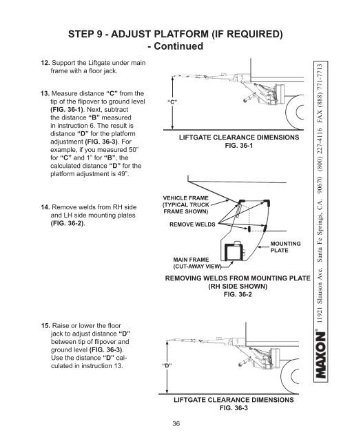
STEP 9 - ADJUST PLATFORM (IF REQUIRED)<br />
- Continued<br />
12. Support the Liftgate under main<br />
frame with a fl oor jack.<br />
13. Measure distance “C” from the<br />
tip of the fl ipover to ground level<br />
(FIG. 36-1). Next, subtract<br />
the distance “B” measured<br />
in instruction 6. The result is<br />
distance “D” for the platform<br />
adjustment (FIG. 36-3). For<br />
example, if you measured 50”<br />
for “C” and 1” for “B”, the<br />
calculated distance “D” for the<br />
platform adjustment is 49”.<br />
14. Remove welds from RH side<br />
and LH side mounting plates<br />
(FIG. 36-2).<br />
15. Raise or lower the fl oor<br />
jack to adjust distance “D”<br />
between tip of fl ipover and<br />
ground level (FIG. 36-3).<br />
Use the distance “D” calculated<br />
in instruction 13.<br />
“C”<br />
LIFTGATE CLEARANCE DIMENSIONS<br />
FIG. 36-1<br />
VEHICLE FRAME<br />
(TYPICAL TRUCK<br />
FRAME SHOWN)<br />
REMOVE WELDS<br />
REMOVING WELDS FROM MOUNTING PLATE<br />
(RH SIDE SHOWN)<br />
FIG. 36-2<br />
“D”<br />
MAIN FRAME<br />
(CUT-AWAY VIEW)<br />
MOUNTING<br />
PLATE<br />
11921 Slauson Ave. Santa Fe Springs, CA. 90670 (800) 227-4116 FAX (888) 771-7713<br />
LIFTGATE CLEARANCE DIMENSIONS<br />
FIG. 36-3<br />
36