GPTLR SERIES (2008 Release) - Maxon
GPTLR SERIES (2008 Release) - Maxon
GPTLR SERIES (2008 Release) - Maxon

You also want an ePaper? Increase the reach of your titles
YUMPU automatically turns print PDFs into web optimized ePapers that Google loves.
STEP 9 - ADJUST PLATFORM (IF REQUIRED)<br />
- Continued<br />
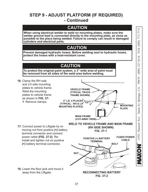
16. Clamp the RH side<br />
and LH side mounting<br />
plates to vehicle frame.<br />
Weld the mounting<br />
plates to vehicle frame<br />
as shown in FIG. 37-<br />
1. Remove clamps.<br />
CAUTION<br />
When using electrical welder to weld on mounting plates, make sure the<br />
welder ground lead is connected directly to the mounting plate, as close as<br />
possible to the place being welded. Failure to comply can result in damaged<br />
cylinders and electrical parts.<br />
CAUTION<br />
Prevent damaged hydraulic hoses. Before welding next to hydraulic hoses,<br />
protect the hoses with a heat-resistant cover.<br />
CAUTION<br />
To protect the original paint system, a 3” wide area of paint must<br />
be removed from all sides of the weld area before welding.<br />
17. Connect power to Liftgate by removing<br />
nut from positive (+) battery<br />
terminal connector and connect<br />
power cable (FIG. 37-2). Reinstall<br />
and tighten nut on positive<br />
(+) battery terminal connector.<br />
VEHICLE FRAME<br />
(TYPICAL TRUCK<br />
FRAME SHOWN)<br />
2” LG. 4 PLACES<br />
(TYPICAL - RH & LH<br />
MOUNTING PLATES)<br />
1/4”<br />
MAIN FRAME<br />
(CUT-AWAY VIEW)<br />
MOUNTING<br />
PLATE<br />
WELD TO VEHICLE FRAME AND MAIN FRAME<br />
(RH SIDE SHOWN)<br />
FIG. 37-1<br />
POSITIVE (+) BATTERY<br />
TERMINAL<br />
FUSED POWER<br />
CABLE<br />
BOLT<br />
11921 Slauson Ave. Santa Fe Springs, CA. 90670 (800) 227-4116 FAX (888) 771-7713<br />
NUT<br />
18. Lower the fl oor jack and move it<br />
away from the Liftgate.<br />
RECONNECTING BATTERY<br />
FIG. 37-2<br />
37