GPTLR SERIES (2008 Release) - Maxon
GPTLR SERIES (2008 Release) - Maxon
GPTLR SERIES (2008 Release) - Maxon

You also want an ePaper? Increase the reach of your titles
YUMPU automatically turns print PDFs into web optimized ePapers that Google loves.
STEP 4 - INSTALL CONTROL SWITCH - Continued<br />
NOTE: MAXON recommends using dielectric grease on all electrical connections.<br />
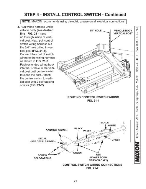
3. Run wiring harness under<br />
vehicle body (see dashed<br />
line - FIG. 21-1) and<br />
up through inside of vertical<br />
post. Next, pull control<br />
switch wiring harness out<br />
the 3/4“ hole drilled in vertical<br />
post (FIG. 21-1).<br />
Connect the control switch<br />
wiring to the wiring harness<br />
as shown in FIG. 21-2.<br />
Push extended wiring back<br />
into the ¾” hole in the vertical<br />
post until control switch<br />
touches the post. Attach<br />
the control switch to vertical<br />
post with 2 self-tapping<br />
screws (FIG. 21-2).<br />
DECAL<br />
(SEE DECALS PAGE)<br />
CONTROL SWITCH<br />
3/4” HOLE VEHICLE BODY<br />
VERTICAL POST<br />
ROUTING CONTROL SWITCH WIRING<br />
FIG. 21-1<br />
BLACK<br />
WHITE<br />
BLACK<br />
WHITE<br />
GREEN<br />
11921 Slauson Ave. Santa Fe Springs, CA. 90670 (800) 227-4116 FAX (888) 771-7713<br />
SCREW,<br />
SELF-TAPPING<br />
GREEN<br />
RED<br />
(POWER DOWN<br />
VERSION ONLY)<br />
CONTROL SWITCH WIRING CONNECTIONS<br />
FIG. 21-2<br />
21