milling of t-slots - Horn USA, Inc.
milling of t-slots - Horn USA, Inc.
milling of t-slots - Horn USA, Inc.

Create successful ePaper yourself
Turn your PDF publications into a flip-book with our unique Google optimized e-Paper software.
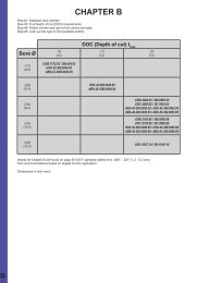
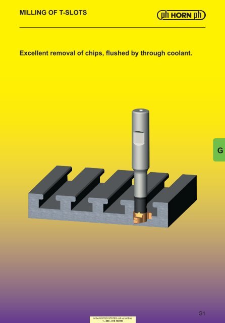
MILLING OF T-SLOTS<br />
Excellent removal <strong>of</strong> chips, flushed by through coolant.<br />
G<br />
In the UNITED STATES call us toll free<br />
1 - 888 - 818 HORN<br />
G1
MILLING OF T-SLOTS<br />
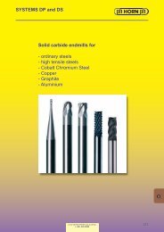
MILLING SHANK Type<br />
MU311<br />
Cutting edge Ø Ds .669″<br />
Material <strong>of</strong> shank: Carbide - Giving a good vibration resistance<br />
for use with Insert<br />
Type<br />
311<br />
G<br />
Picture = right hand cutting version shown<br />
Part number Ds l 1<br />
l 2<br />
d 1<br />
d<br />
MU311.0625.00B .669 3.543 .984 .354 .625<br />
Further sizes upon request<br />
Ordering note:<br />
Milling cutter shanks with damaged seating can be repaired by HORN.<br />
Dimensions in inch<br />
Spare parts<br />
Milling shank Screw Torque TORX PLUS® Wrench<br />
MU311.0625.00B 4.16T15KP 35 - 40 lbf-in. T15PQ<br />
G2<br />
In the UNITED STATES call us toll free<br />
1 - 888 - 818 HORN
MILLING OF T-SLOTS<br />
MILLING SHANK Type<br />
M311<br />
Cutting edge Ø<br />
Ds .669″ (17.0 mm)<br />
Material <strong>of</strong> shank: Carbide - Giving a good vibration resistance<br />
for use with Insert<br />
Type<br />
311<br />
Picture = right hand cutting version shown<br />
G<br />
Part number Ds l 1<br />
l 2<br />
d 1<br />
d<br />
M311.0016.00B 17 90 25 9 16<br />
M311.0016.00E 17 90 25 9 16<br />
Further sizes upon request<br />
Ordering note:<br />
Milling cutter shanks with damaged seating can be repaired by HORN.<br />
Dimensions in mm<br />
Spare parts<br />
Milling shank Screw Torque TORX PLUS® Wrench<br />
M311.0016.00... 4.16T15KP 35 - 40 lbf-in. T15PQ<br />
In the UNITED STATES call us toll free<br />
1 - 888 - 818 HORN<br />
G3
MILLING OF T-SLOTS<br />
INSERT Type<br />
311<br />
T-Slots DIN 650<br />
Cutting edge Ø<br />
a .394″<br />
Ds .669″<br />
for use with Milling shank<br />
Type<br />
M311<br />
G<br />
Picture = right hand cutting version shown<br />
Part number Ds w s r 1<br />
r 2<br />
a<br />
MG12<br />
TI25<br />
TF45<br />
311.1016.00 .669 .283 .303 .020 .031 .394 •<br />
Dimensions in inch<br />
●/+ = on stock / 6 weeks<br />
Further sizes upon request<br />
G4<br />
In the UNITED STATES call us toll free<br />
1 - 888 - 818 HORN
CHAMFERING OF T-SLOTS<br />
INSERT Type<br />
311<br />
T-Slots DIN 650<br />
Cutting edge Ø<br />
a .394/.472/.551″<br />
Ds .622″<br />
for use with Milling shank<br />
Type<br />
M311<br />
Picture = right hand cutting version shown<br />
G<br />
Part number s E Ds<br />
MG12<br />
TN35<br />
TI25<br />
TF45<br />
311.4216.00 .230 .118 .622 •<br />
Dimensions in inch<br />
●/+ = on stock / 6 weeks<br />
Further sizes upon request<br />
In the UNITED STATES call us toll free<br />
1 - 888 - 818 HORN<br />
G5
MILLING OF T-SLOTS<br />
MILLING SHANK Type<br />
MU313<br />
Cutting edge Ø Ds .787″<br />
Material <strong>of</strong> shank: Carbide - Giving a good vibration resistance<br />
for use with Insert<br />
Type<br />
313<br />
G<br />
Picture = right hand cutting version shown<br />
Part number Ds l 1<br />
l 2<br />
d 1<br />
d<br />
MU313.0625.00B .787 3.661 1.181 .453 .625<br />
Further sizes upon request<br />
Ordering note:<br />
Milling cutter shanks with damaged seating can be repaired by HORN.<br />
Dimensions in inch<br />
Spare parts<br />
Milling shank Screw Torque TORX PLUS® Wrench<br />
MU313.0625.00B 5.13T20KP 53 - 58 lbf-in. T20PQ<br />
G6<br />
In the UNITED STATES call us toll free<br />
1 - 888 - 818 HORN
MILLING OF T-SLOTS<br />
MILLING SHANK Type<br />
M313<br />
Cutting edge Ø<br />
Ds .787″ (20.0 mm)<br />
Material <strong>of</strong> shank: Carbide - Giving a good vibration resistance<br />
for use with Insert<br />
Type<br />
313<br />
Picture = right hand cutting version shown<br />
G<br />
Part number Ds l 1<br />
l 2<br />
d 1<br />
d<br />
M313.0016.00B 20 93 30 11.5 16<br />
M313.0016.00E 20 93 30 11.5 16<br />
Further sizes upon request<br />
Ordering note:<br />
Milling cutter shanks with damaged seating can be repaired by HORN.<br />
Dimensions in mm<br />
Spare parts<br />
Milling shank Screw Torque TORX PLUS® Wrench<br />
M313.0016.00... 5.13T20KP 53 - 58 lbf-in. T20PQ<br />
In the UNITED STATES call us toll free<br />
1 - 888 - 818 HORN<br />
G7
MILLING OF T-SLOTS<br />
INSERT Type<br />
313<br />
T-Slots DIN 650<br />
Cutting edge Ø<br />
a .472″<br />
Ds .787″<br />
for use with Milling shank<br />
Type<br />
M313<br />
G<br />
Picture = right hand cutting version shown<br />
Part number Ds w s r 1<br />
r 2<br />
a<br />
MG12<br />
TI25<br />
TF45<br />
313.1219.00 .787 .323 .343 .020 .031 .472 •<br />
Dimensions in inch<br />
●/+ = on stock / 6 weeks<br />
Further sizes upon request<br />
G8<br />
In the UNITED STATES call us toll free<br />
1 - 888 - 818 HORN
MILLING OF T-SLOTS<br />
MILLING SHANK Type<br />
MU328<br />
Cutting edge Ø Ds .945″<br />
Material <strong>of</strong> shank: Carbide - Giving a good vibration resistance<br />
for use with Insert<br />
Type<br />
328<br />
Picture = right hand cutting version shown<br />
G<br />
Part number Ds l 1<br />
l 2<br />
d 1<br />
d<br />
MU328.0750.00B .945 4.094 1.378 .531 .750<br />
Further sizes upon request<br />
Ordering note:<br />
Milling cutter shanks with damaged seating can be repaired by HORN.<br />
Dimensions in inch<br />
Spare parts<br />
Milling shank Screw Torque TORX PLUS® Wrench<br />
MU328.0750.00B 5.13T20KP 53 - 58 lbf-in. T20PQ<br />
In the UNITED STATES call us toll free<br />
1 - 888 - 818 HORN<br />
G9
MILLING OF T-SLOTS<br />
MILLING SHANK Type<br />
M328<br />
Cutting edge Ø<br />
Ds .945″ (24.0 mm)<br />
Material <strong>of</strong> shank: Carbide - Giving a good vibration resistance<br />
for use with Insert<br />
Type<br />
328<br />
G<br />
Picture = right hand cutting version shown<br />
Part number Ds l 1<br />
l 2<br />
d 1<br />
d<br />
M328.0020.00B 24 104 35 13.5 20<br />
M328.0020.00E 24 104 35 13.5 20<br />
Further sizes upon request<br />
Ordering note:<br />
Milling cutter shanks with damaged seating can be repaired by HORN.<br />
Dimensions in mm<br />
Spare parts<br />
Milling shank Screw Torque TORX PLUS® Wrench<br />
M328.0020.00... 5.13T20KP 53 - 58 lbf-in. T20PQ<br />
G10<br />
In the UNITED STATES call us toll free<br />
1 - 888 - 818 HORN
MILLING OF T-SLOTS<br />
INSERT Type<br />
328<br />
T-Slots DIN 650<br />
Cutting edge Ø<br />
a .551″<br />
Ds .945″<br />
for use with Milling shank<br />
Type<br />
M328<br />
Picture = right hand cutting version shown<br />
G<br />
Part number Ds w s r 1<br />
r 2<br />
a<br />
MG12<br />
TI25<br />
TF45<br />
328.1423.00 .945 .362 .386 .020 .039 .551 •<br />
Dimensions in inch<br />
●/+ = on stock / 6 weeks<br />
Further sizes upon request<br />
In the UNITED STATES call us toll free<br />
1 - 888 - 818 HORN<br />
G11
MILLING OF T-SLOTS<br />
Application Technology<br />
a 2<br />
≈ 0.2 x s<br />
very recommandable<br />
not recommandable<br />
CUTTING DATA<br />
MILLING OF T-SLOTS<br />
G<br />
Workpiece material Cutting material v c<br />
[sfm] f z<br />
= IPT<br />
Ds .669"<br />
f z<br />
= IPT<br />
Ds .787"-.945"<br />
Carbon steel TI25 650 - 980 .0012 - .0025 .0020 - .0031<br />
Alloyed steel TI25 460 - 720 .0008 - .0016 .0012 - .0020<br />
Cast iron TI25 330 - 520 .0012 - .0025 .0020 - .0039<br />
CUTTING DATA<br />
CHAMFERING OF T-SLOTS<br />
Workpiece material Cutting material v c<br />
[sfm] f z<br />
= IPT<br />
Carbon steel TI25 980 - 1300 .0051 - .0083<br />
Alloyed steel TI25 590 - 980 .0039 - .0051<br />
Cast iron TI25 460 - 790 .0063 - .0106<br />
The cutting data are only valid for our available antivibration standard carbide toolholders (shanks).<br />
G12<br />
In the UNITED STATES call us toll free<br />
1 - 888 - 818 HORN
TECHNICAL INFORMATION<br />
Feed rates and time calculation<br />
It is simple and easy to calculate your speed and feeds<br />
using HORN‘S HCT program. We recommend that<br />
you calculate the cutting data with this program as it<br />
will provide you with the best cutting performance and<br />
results. Basic features <strong>of</strong> the calculations can be found<br />
on the follwing pages.<br />
HCT<br />
(HORN Circular Technology)<br />
- safe and fast -<br />
Your cutting data for groove <strong>milling</strong> by<br />
circular interpolation <strong>of</strong> internal and<br />
external grooves as well as groove<br />
<strong>milling</strong> <strong>of</strong> linear grooves.<br />
System requirements from Windows 95.<br />
Available on CD-ROM.<br />
BASIC RECOMMENDATIONS<br />
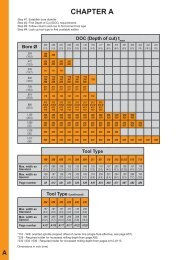
Overhang <strong>of</strong> the <strong>milling</strong> cutter<br />
Select the shortest possible clamping device and <strong>milling</strong><br />
shank, and control the runout tolerance <strong>of</strong> the tools.<br />
Large cutting widths in combination with long overhangs<br />
require specific manufacturing methods such as dividing<br />
the cutting width to achieve the best possible cutting<br />
result due to reduced cutting forces.<br />
H<br />
Diameter <strong>of</strong> the <strong>milling</strong> cutter<br />
When using a large diameter cutter, whose relationship<br />
is close to the bore diameter, manufacturing cycletime<br />
can be reduced, due to the smaller center <strong>of</strong> rotation and<br />
higher feed rates. Many times the rotation <strong>of</strong> the <strong>milling</strong><br />
cutter centre will be defined by the parameters <strong>of</strong> the<br />
workpiece and the whole application setup.<br />
Clamping torque <strong>of</strong> the screws<br />
We recommend to use a torque screw driver to achieve<br />
the indicated torque values per insert and tool type.<br />
Additional additives such as copper paste are not<br />
permitted. This will have a negative effect and change<br />
the clamping forces.<br />
All clamping screws are already coated with<br />
additives.<br />
M d<br />
In the UNITED STATES call us toll free<br />
1 - 888 - 818 HORN<br />
H1
TECHNICAL INFORMATION<br />
Milling direction<br />
Most HORN <strong>milling</strong> tools are right handed , and it is<br />
recommended to use them with the climb <strong>milling</strong> process<br />
as this is generally recommend for carbide tools.<br />
H<br />
Milling entry into the workpiece<br />
A simple radial entry <strong>of</strong> the <strong>milling</strong> cutter creates a very<br />
long contact angle which leads to vibrations which will<br />
not disappear for the rest <strong>of</strong> the <strong>milling</strong> operation and are<br />
visual on the bottom <strong>of</strong> the groove.<br />
It is recommended to enter the groove with a ramp<br />
angle <strong>of</strong> 45° up to 180° to the maximum depth <strong>of</strong> cut.<br />
The calculated cutting data refers to the <strong>milling</strong> condition<br />
when the insert is in the full cut but can be also used for<br />
the entry loop.<br />
Ramp angle > 45°<br />
Bore <strong>milling</strong> and <strong>of</strong>fset <strong>milling</strong> by helical<br />
interpolation<br />
HORN <strong>milling</strong> inserts are manufactured with a round chip<br />
breaker. This means that beyond a depth <strong>of</strong> cut <strong>of</strong> 2 mm<br />
in axial direction the insert gets a negative cutting angle.<br />
Milling inserts are limited to a depth <strong>of</strong> cut <strong>of</strong> 2 mm when<br />
used for helical interpolation. Larger depths <strong>of</strong> cut can<br />
only be produced when choosing special chip breakers.<br />
Please contact us in case <strong>of</strong> any further questions.<br />
H2<br />
In the UNITED STATES call us toll free<br />
1 - 888 - 818 HORN
TECHNICAL INFORMATION<br />
Sinlge edged inserts<br />
When entering through a bore <strong>of</strong>f center and without<br />
rotating it is possible to generate back chamfers and<br />
flats with inserts having a larger cutting diameter than<br />
the bore diameter. Single edged cutters have no run out<br />
tolerance.<br />
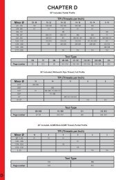
Thread <strong>milling</strong><br />
H<br />
With HORN thread <strong>milling</strong> inserts the thread pr<strong>of</strong>ile is<br />
generated in one full cut to the pr<strong>of</strong>ile depth <strong>of</strong> the thread.<br />
This produces threads with minimal taper especially in<br />
high alloyed steels.<br />
In blind holes it is recommended to mill from the bottom<br />
to the top. Otherwise there is the risk <strong>of</strong> damaging the<br />
tool because <strong>of</strong> <strong>milling</strong> into chips at the bottom <strong>of</strong> the<br />
blind hole.<br />
A general recommendation for thread <strong>milling</strong>:<br />
The <strong>milling</strong> cutter diameter should not exceed 70% <strong>of</strong> the<br />
minor diameter <strong>of</strong> the thread. Otherwise recutting <strong>of</strong> the<br />
pr<strong>of</strong>ile occurs which could bring the whole thread out <strong>of</strong><br />
tolerance.<br />
In the UNITED STATES call us toll free<br />
1 - 888 - 818 HORN<br />
H3
CHOICE OF CARBIDE GRADES<br />
Synthetic cutting-tool material<br />
PD10<br />
PD20<br />
Wear resistance<br />
Cutting speed<br />
Toughness<br />
Feed rate<br />
CB10<br />
CB20<br />
H<br />
Carbide Grades<br />
uncoated coated<br />
MG12 TI25<br />
MG12 TN35 TH35<br />
01<br />
10<br />
20<br />
30<br />
40<br />
10<br />
20<br />
30<br />
N<br />
40<br />
01<br />
10<br />
20<br />
30<br />
Non ferrous metal High temp. alloys Hardened materials<br />
S<br />
H<br />
Wear resistance<br />
Cutting speed<br />
Toughness<br />
Feed rate<br />
01<br />
10<br />
20<br />
30<br />
40<br />
10<br />
20<br />
30<br />
40<br />
01<br />
10<br />
20<br />
30<br />
P<br />
Carbide Grades<br />
Main selection supplementary grades<br />
H35<br />
TH35<br />
TN35<br />
TI25<br />
H54 TF45<br />
MG12<br />
TN35<br />
TI25<br />
H54<br />
TF45<br />
MG12<br />
TF46<br />
Steel Stainless steel Grey cast iron / Aluminium<br />
M<br />
K<br />
H4<br />
In the UNITED STATES call us toll free<br />
1 - 888 - 818 HORN
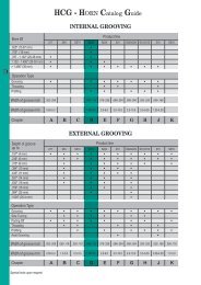
GROOVE MILLING by circular interpolation<br />
MILLING OF A LINEAR GROOVE - EXTERNAL<br />
s z<br />
= h m<br />
√ 2r a r<br />
s = n • z • s z<br />
mm/min<br />
H<br />
Cos φ° = r2 + [R + r - a r<br />
] 2 - R 2 φ°<br />
2r [R + r - a r<br />
]<br />
L = • 2r • φ° mm<br />
360°<br />
Length <strong>of</strong> cut<br />
t =<br />
A T<br />
n • z • A z<br />
min<br />
Time for cut (for A T<br />
)<br />
A Z<br />
= L • h м<br />
mm 2 s' 2<br />
= s' 1<br />
Area <strong>of</strong> chip<br />
s' 1<br />
= • 2 (R+r-a r ) mm/min<br />
t<br />
Feed rate <strong>of</strong> tool centre<br />
A T<br />
= [R 2 -(R-a r<br />
) 2 ] mm 2<br />
Area <strong>of</strong> groove section<br />
R - a r<br />
R + r - a r<br />
mm/min<br />
Feed rate <strong>of</strong> tool tip<br />
HCT (HORN Circular Technology)<br />
- safe and fast -<br />
Your cutting data for groove <strong>milling</strong> by circular interpolation <strong>of</strong> internal and external grooves as well as groove <strong>milling</strong><br />
<strong>of</strong> linear grooves.<br />
System requirements from Windows 95. Available on CD-ROM.<br />
In the UNITED STATES call us toll free<br />
1 - 888 - 818 HORN<br />
H5
GROOVE MILLING by circular interpolation<br />
MILLING OF AN INTERNAL GROOVE<br />
H<br />
Cos [180° - φ°] = r2 + [R + a r<br />
- r] 2 - R 2 180° - φ° φ°<br />
2r [R + a r<br />
- r]<br />
L = • 2r • φ° mm<br />
360°<br />
Length <strong>of</strong> cut<br />
t =<br />
A T<br />
n • z • A z<br />
min<br />
Time for cut (for A T<br />
)<br />
A Z<br />
= L • h m<br />
mm 2 s' 2<br />
= s' 1<br />
Area <strong>of</strong> chip<br />
s' 1<br />
= • 2 (R+r-a r ) mm/min<br />
t<br />
Feed rate <strong>of</strong> tool centre<br />
A T<br />
= [R 2 -(R-a r<br />
) 2 ] mm 2<br />
Area <strong>of</strong> groove section<br />
R - a r<br />
R + r - a r<br />
mm/min<br />
Feed rate <strong>of</strong> tool tip<br />
Specification<br />
ISO Specification Specification ISO Specification<br />
Feed rate<br />
Revolutions<br />
Number <strong>of</strong> teeth<br />
Feed/tooth<br />
medium thickness <strong>of</strong><br />
chip<br />
radial depth <strong>of</strong> cut<br />
r r<br />
s'<br />
v f<br />
Radius <strong>of</strong> cutter<br />
a r<br />
a e<br />
n<br />
n<br />
Radius <strong>of</strong> workpiece<br />
R<br />
R<br />
z<br />
s z<br />
z<br />
f z<br />
Feed rate <strong>of</strong> tool centre<br />
s‘ 1<br />
v f 3<br />
h m<br />
h m<br />
Feed rate <strong>of</strong> tool tip<br />
s‘ 2<br />
v f2<br />
H6<br />
In the UNITED STATES call us toll free<br />
1 - 888 - 818 HORN
Available METRIC size carbide and tungsten<br />
alloy shanks - Summary<br />
Dimensions in mm Part number Inserts (inch and metric) Use Page<br />
l 1<br />
d g6<br />
l 2<br />
d 1<br />
Type t max<br />
Ds<br />
130 12 40 11 M116.0012.01B<br />
130 12 56 11 M116.0012.02B<br />
130 16 40 11 M116.0016.01B/E<br />
130 16 56 11 M116.0016.02B/E<br />
150 16 80 11 M116.0016.03B/E<br />
80 12 21 6 M306.0012.01B/E/A<br />
90 12 30 6 M306.0012.02B/E/A<br />
100 12 42 6 M306.0012.03B/E/A<br />
116 4.3 20.4 A53<br />
116 4.3 20.4 A53<br />
108/306 1.0/2.5 9.6/11.7 A3 - A4<br />
100 7.5 - 6 M306.0707.03A<br />
D3; E2<br />
108/306 0.85/2.0 9.3/11.7<br />
120 10 - 6 M306.1010.03A E2<br />
90 12 30 7.3 M306.0712.02B/E/A<br />
100 16 25 7.3 M306.0716.01/B/E/A<br />
108/306 0.7/2.0 9.6/11.7 A3 - A4; D3<br />
60 10 15.2 6 M306.ST10.01A 108/306 1.0/2.5 9.4/11.7 A5<br />
95 12 29 8 M308.0012.01B/E/A<br />
110 12 42 8 M308.0012.02B/E/A<br />
120 12 56 8 M308.0012.03B/E/A<br />
111/308/608 2.3/3.5 13.4/15.7 A23-A24<br />
160 12 - - M308.0012.07A 111/308/608 2.3/3.5 13.4/15.7 D11; E8<br />
110 12 42 9.5 M308.1012.02B/E/A<br />
110 16 33 9.5 M308.1016.01B/E/A<br />
60 10 17.7 8 M308.ST10.01A<br />
70 13 25.7 8 M308.ST13.01A<br />
100 12 32 9 M311.0012.01B/E/A<br />
100 12 45 9 M311.0012.02B/E/A<br />
120 12 64 9 M311.0012.03B/E/A<br />
111/308 1.5/2.7 13.4/15.7 A23-A24; D11<br />
111/308 2.3/3.5 13.4/15.7 A25<br />
311/611 3.5/2.5 17.7 A39-A40<br />
90 16 25 9 M311.0016.00B/E 311 3.6 17.0 G3<br />
100 16 32 9 M311.0016.01B/E/A<br />
110 16 45 9 M311.0016.02B/E/A<br />
130 16 64 9 M311.0016.03B/E/A<br />
110 16 32 13 M311.0016.04B/E/A<br />
130 16 45 13 M311.0016.05B/E/A<br />
60 10 17.7 9 M311.ST10.01A<br />
311/611 3.5/2.5 17.7 A39-A40<br />
311/611 1.5 17.7 A39-A40; D21<br />
70 13 25.7 9 M311.ST13.01A 311/611 3.5 17.7<br />
A41<br />
80 16 25.7 9 M311.ST16.01A<br />
100 12 - - M313.0012.01B/E/A<br />
130 12 - - M313.0012.02B/E/A<br />
313/613 4.5/3.2 21.7 A59-A60<br />
93 16 30 11.5 M313.0016.00B/E 313 4.75 21.7 G7<br />
100 16 42 12 M313.0016.01B/E/A<br />
130 16 60 12 M313.0016.02B/E/A<br />
160 16 85 12 M313.0016.03B/E/A<br />
160 16 20 12 M313.0016.07A<br />
110 20 45 16 M313.0020.04B/E<br />
130 20 60 16 M313.0020.05B/E<br />
313/613 4.5/3.2 21.7 A59-A60<br />
313/613 2.5 21.7 D35<br />
H<br />
Dimensions in mm<br />
In the UNITED STATES call us toll free<br />
1 - 888 - 818 HORN<br />
H7
Available METRIC size carbide and tungsten<br />
alloy shanks - Summary<br />
Dimensions in mm Part number Inserts (inch and metric) Use Page<br />
l 1<br />
d g6<br />
l 2<br />
d 1<br />
Type t max<br />
Ds<br />
60 10 10.7 11.3 M313.ST10.01A<br />
70 13 25.7 11.3 M313.ST13.01A<br />
80 16 25.7 11.3 M313.ST16.01A<br />
120 9 - - M328.0909.01A<br />
100 12 36 9 M328.0912.01A<br />
100 16 42 14.3 M328.0016.01B/E/A<br />
130 16 60 14.3 M328.0016.02B/E/A<br />
160 16 85 14.3 M328.0016.03B/E/A<br />
100 20 42 14.3 M328.0020.01B/E/A<br />
130 20 60 14.3 M328.0020.02B/E/A<br />
160 20 85 14.3 M328.0020.03B/E/A<br />
313/613 4.85 21.7 A61<br />
328/628 9.3 28 A79<br />
325/328/628 5.0/6.4/4.3 24.8/27.7 A77 - A78<br />
104 20 35 13.5 M328.0020.00B/E 328 6.5 27.7 G10<br />
H<br />
130 20 20 15 SM328.0020.05B/E<br />
6.0<br />
145 20 - - SM328.0020.06B/E 3.5<br />
328<br />
160 20 20 15 SM328.0020.07B/E 6.0<br />
27.7 D43<br />
200 20 - - SM328.0020.08B/E 3.5<br />
70 13 10.7 14 M328.ST13.01A<br />
100 20 35.7 14 M328.ST20.01A<br />
328/628 6.0 27.7 A80<br />
100 16 42 16 M332.0016.01A<br />
130 16 60 16 M332.0016.02A<br />
160 16 85 16 M332.0016.03A<br />
100 20 42 20 M332.0020.01A<br />
332 8.5 31.7 A92<br />
130 20 60 20 M332.0020.02A<br />
160 20 85 20 M332.0020.03A<br />
100 12 32 11 M332.0012.2.01A<br />
100 16 32 11 M332.0016.2.01A<br />
332 10 31.7<br />
A93<br />
70 13 25 11 M332.ST13.2.01A A94<br />
100 20 40 17.5 M335.0020.01B/A<br />
130 20 60 17.5 M335.0020.02B/A/E<br />
335 7.9/8.0 34.7 A104 - A105<br />
Dimensions in mm<br />
H8<br />
In the UNITED STATES call us toll free<br />
1 - 888 - 818 HORN
Available INCH size carbide and tungsten<br />
alloy shanks - Summary<br />
Diemsnions in inch Part number Inserts (inch and metric) Use Page<br />
l 1<br />
d g6<br />
l 2<br />
d 1<br />
Type t max<br />
Ds<br />
3.150 .500 .827 .236 MU306.0500.01B 108/306 .039/.098 .378/.461<br />
3.543 .500 1.181 .236 MU306.0500.02B 108/306 .039/.098 .378/.461 A2; D2<br />
3.937 .500 1.654 .236 MU306.0500.03B 108/306 .039/.098 .378/.461<br />
3.937 .625. .984 .287 MU306.0625.01B 108/306 .028/.078 .378/.461<br />
3.740 .500 1.142 .315 MU308.0500.01B 111/308 .091/.138 .528/.618<br />
4.331 .500 1.654 .315 MU308.0500.02B 111/308 .091/.138 .528/.618 A22; D10<br />
4.724 .500 2.205 .315 MU308.0500.03B 111/308 .091/.138 .528/.618<br />
4.331 .625 1.299 .315 MU308.0625.01B 111/308 .091/.138 .528/.618<br />
3.937 .500 1.260 .354 MU311.0500.01B 311/611 .138 .697<br />
3.937 .500 1.772 .354 MU311.0500.02B 311/611 .138 .697 A38<br />
4.724 .500 2.520 .354 MU311.0500.03B 311/611 .138 .697<br />
3.543 .625 .984 .354 MU311.0625.00B 311 .143 .669 G2<br />
3.937 .625 1.260 .354 MU311.0625.01B 311/611 .138 .697<br />
4.331 .625 1.772 .354 MU311.0625.02B 311/611 .138 .697 A38<br />
5.118 .625 2.520 .354 MU311.0625.03B 311/611 .138 .697<br />
4.331 .625 1.260 .512 MU311.0625.04B 311 .059 .697 A38; D20<br />
5.118 .625 1.772 .512 MU311.0625.05B 311 .059 .697<br />
6.301 .500 - .354 MU311.1212.07A 313/613 .177 .854<br />
H<br />
3.937 .500 - - MU313.0500.01B 313/613 .177 .854 A58<br />
5.118 .500 - - MU313.0500.02B 313/613 .177 .854<br />
3.661 .625 1.181 .453 MU313.0625.00B 313 .187 .787 G6<br />
3.937 .625 1 .654 .472 MU313.0625.01B 313/613 .177 .854<br />
5.118 .625 2 .362 .472 MU313.0625.02B 313/613 .177 .854 A58<br />
6.299 .625 3 .346 .472 MU313.0625.03B 313/613 .177 .854<br />
4.331 .750 1 .772 .630 MU313.0750.04B 313/613 .098 .854 D34<br />
5.118 .750 2 .559 .630 MU313.0625.05B 313/613 .098 .854<br />
7.874 .625 - .445 MU313.1515.08A 313/613 .098 .854<br />
3.937 .500 - .563 MU328.0500.01B 328/628 .256 1.091<br />
5.118 .500 - .563 MU328.0500.02B 328/628 .256 1.091<br />
3.937 .625 1 .654 .563 MU328.0625.01B 328/628 .256 1.091 A76<br />
5.118 .625 2 .362 .563 MU328.0625.02B 328/628 .256 1.091<br />
6.299 .625 3 .346 .563 MU328.0625.03B 328/628 .256 1.091<br />
6.299 .750 3 .346 .563 MU328.0750.03B 328/628 .256 1.091<br />
4.094 .750 1.378 .531 MU328.0750.00B 328 .256 .945 G9<br />
5.118 .750 .787 .591 SMU328.0750.05B 328 .236 1.091<br />
5.709 .750 - - SMU328.0750.06B 328 .138 1.091<br />
6.299 .750 .787 .591 SMU328.0750.07B 328 .236 1.091 D42<br />
7.874 .750 - - SMU328.0750.08B 328 .138 1.091<br />
Dimensions in inch<br />
In the UNITED STATES call us toll free<br />
1 - 888 - 818 HORN<br />
H9
CUTTING DATA<br />
Standard values for cutting speeds v c<br />
and medium thickness h m<br />
for calculating feed rates by calculating cutting programm »HCT«.<br />
Material<br />
P<br />
Carbon steel<br />
Hardness Brinell<br />
Cutting speeds v c<br />
(sfm)<br />
refering to carbide grade<br />
and coating<br />
MG12<br />
TN35<br />
TI25<br />
TF45<br />
*H35<br />
0.2% C 140 - 790 650-1150<br />
0.4% C 180 - 690 650-980<br />
medium thickness <strong>of</strong> chip h m<br />
Indexable Insert Type 314<br />
Insert Type<br />
311/313/328/108/111/ 116<br />
very rigid rigid not rigid very rigid rigid not rigid<br />
0.6% C 200 - 520 500-820<br />
annealed 180 - 490 590<br />
.0039<br />
.0020<br />
.0012<br />
.0020<br />
.0012<br />
.0004<br />
Alloyed steel<br />
quenched 280 - 390 520<br />
quenched 350 - 230 -<br />
H<br />
high alloyed steel<br />
(>5%)<br />
Cast steel<br />
annealed 200 - 230 -<br />
hardened - - - - - - - - - -<br />
unalloyed 180 80 430 -<br />
alloyed 220 70 390 -<br />
M<br />
K<br />
Stainless steel<br />
Cast iron<br />
martensitic, ferritic 200 80 590 -<br />
austenitic 180 70 390 -<br />
low tensile strength 180 70 330 -<br />
high tensile strength 250 60 390 -<br />
Spheroidal graphite<br />
cast iron<br />
ferritic 160 70 330 -<br />
perlitic 250 - 300 -<br />
Malleable cast iron<br />
S<br />
Heat resistant alloy<br />
(Fe)<br />
ferritic 125 60 330 -<br />
perlitic 225 70 200 -<br />
annealed 200 40 260 -<br />
hardened 275 30 - -<br />
.0039<br />
.0020<br />
.0012<br />
.0020<br />
.0012<br />
.0004<br />
Heat resistant alloy<br />
(Ni, Co)<br />
annealed 250 20 130 -<br />
hardened 350 15 - -<br />
N<br />
Al-alloy<br />
not heat treatable 30-80 550 2600 -<br />
heat treatable 80-120 220 980 -<br />
Al-cast-alloy<br />
not heat treatable 80 220 980 -<br />
heat treatable 100 100 660 -<br />
H10<br />
Copper-alloy<br />
not heat treatable 90 120 - -<br />
heat treatable 100 100 - -<br />
In the UNITED STATES call us toll free<br />
1 - 888 - 818 HORN<br />
*Cermet only indexable insert type 314 available
COMPONENT<br />
Torque screw driver with scale<br />
- variable torque setting<br />
- adjusted torque is shown on display<br />
D 15 VL<br />
Model 1-5 Nm<br />
The Torque can be infinitely adjusted with a special torque<br />
setter (id.) Ergonomical formed gives perfect handling<br />
abilities. Acustic signal when setted torque is reached.<br />
(Standard: EN ISO 6798, BS EN 26789, ASME B 107.14.M.)<br />
(Precision: ± 6 %)<br />
D 28 VL<br />
Model 2-8 Nm<br />
Torque screw driver with scale<br />
- variable torque setting<br />
- adjusted torque is shown on display<br />
The Torque can be infinitely adjusted with a special torque<br />
setter (id.) Ergonomical formed gives perfect handling<br />
abilities. Acustic signal when setted torque is reached.<br />
(Standard: EN ISO 6798, BS EN 26789, ASME B 107.14.M.)<br />
(Precision: ± 6 %)<br />
Torque setter<br />
ED 28 VL<br />
Device for setting the required torque.<br />
Handle: Celluloseacetat with micro structured surface<br />
Blade: Octogonal (8 flats) blade, hardened galvanized<br />
In the UNITED STATES call us toll free<br />
1 - 888 - 818 HORN<br />
O1<br />
O
COMPONENT<br />
Blade for TORX-Plus screws<br />
DT6PK<br />
DT7PK<br />
DT8PK<br />
DT9PK<br />
DT10PK<br />
DT15PK<br />
DT20PK<br />
DT25PK<br />
Blade:<br />
Utilization:<br />
High quality Chrom-Vanadium steel,<br />
through hardened, chrome plated.<br />
Wiha Chrom Blade guarantees maximum<br />
precison.<br />
Colored code green<br />
For controlled screw setting with definite torque<br />
in combination with Wiha torque screw driver<br />
handle.<br />
Blade for allen screws<br />
DSW15K<br />
DSW20K<br />
DSW25K<br />
DSW30K<br />
DSW40K<br />
Blade:<br />
Utilization:<br />
High quality chrom-vanadium steel,<br />
through hardened, chrome plated.<br />
Wiha Chrom Blade guarantees maximum<br />
precison.<br />
Colored code red<br />
controlled screw setting with definite torque in<br />
combination with Wiha torque screw driver<br />
handel<br />
D14ZBK<br />
Universal Bitholder<br />
For S.DM08, S.DM10 and S.DM12 also<br />
for all C6,3 and E6,3 (1/4") Bits<br />
Blade: High quality Chrome-Vanadium steel,<br />
through hardened, chrome plated.<br />
Collar:<br />
Utilization:<br />
Stainless steel<br />
For controlled screw setting with definite torque<br />
in combination with torque screw driver handle.<br />
O<br />
O2<br />
In the UNITED STATES call us toll free<br />
1 - 888 - 818 HORN
COMPONENT<br />
Universal Bitholder with T-handle<br />
For S.DM10 and S.DM12<br />
also for all C6,3 and E6,3 (1/4") Bits<br />
Blade: High quality Chrome-Vanadium steel,<br />
through hardened, chrome plated.<br />
Collar: Stainless steel<br />
Utilization: For controlled opening<br />
14ZQK<br />
Torque screw driver with scale<br />
- variable torque setting<br />
- adjusted torque is shown on display<br />
The Torque can be infinitely adjusted with a special torque<br />
setter (id.) Ergonomical formed gives perfect handling<br />
abilities. Acustic signal when setted torque is reached.<br />
(Standard: EN ISO 6798, BS EN 26789, ASME B 107.14.M.)<br />
(Precision: ± 6 %)<br />
D515QL<br />
Model 5-15 Nm<br />
ED515QL<br />
Torque setter<br />
Device for setting the required torque.<br />
Handle: Celluloseacetat with micro structured surface<br />
Blade: Octogonal (8 flats) blade, hardened galvanized<br />
In the UNITED STATES call us toll free<br />
1 - 888 - 818 HORN<br />
O3<br />
O
COMPONENT<br />
Universal Bitholder<br />
For S.DM08, S.DM10 and S.DM12 also<br />
for all C6,3 and E6,3 (1/4") Bits<br />
D14ZBQ<br />
Blade:<br />
Collar:<br />
Utilization:<br />
High quality Chrome-Vanadium steel,<br />
through hardened, chrome plated.<br />
Stainless steel<br />
For controlled screw setting with definite torque<br />
in combination with torque screw driver handle.<br />
Blade for TORX-Plus screws<br />
DT15PQ<br />
DT20PQ<br />
DT25PQ<br />
DT27PQ<br />
DT30PQ<br />
Blade:<br />
Utilization:<br />
High quality Chrom-Vanadium steel,<br />
through hardened, chrome plated.<br />
Wiha Chrom Blade guarantees maximum<br />
precison.<br />
Colored code green<br />
For controlled screw setting with definite<br />
torque in combination with Wiha torque screw<br />
driver handle.<br />
O<br />
O4<br />
In the UNITED STATES call us toll free<br />
1 - 888 - 818 HORN
METAL CUTTING SAFETY<br />
During metal cutting "hot flying chips" may be projected from the workpiece<br />
or a rotating part <strong>of</strong> the machine tool. If carbide is subjected to over-stress<br />
or severe impact, it may fracture causing small fragments to be dispelled.<br />
In such instances, certains precautions should be implemented to protect<br />
the operator(s) and/or observer(s) against "hot flying chips.<br />
Boring operations or applications "tempts" the operator to "lean over" the<br />
rotating workpiece to check the cutting action. Extra caution should be<br />
exercised in doing this and it is recommended that no one practice this<br />
habit while tools or machinery or both are spinning, turning, rotating etc.<br />
Grinding products in this catalog will produce dust and/or mist that may be<br />
hazardous. See material data safety sheets (available upon request).<br />
HORN <strong>USA</strong> <strong>Inc</strong>. has no control over conditions to which it's products may<br />
be or subjected to. Therefore it is highly recommended that the user <strong>of</strong><br />
HORN <strong>USA</strong> <strong>Inc</strong>. products listed in this catalog and all the literature <strong>of</strong><br />
this company, abide by the standards <strong>of</strong> use for their particular cutting<br />
machines and commonly used safety precautions.<br />
Designs and/or specifications <strong>of</strong> products listed in this catalog and all<br />
the literature <strong>of</strong> HORN <strong>USA</strong> <strong>Inc</strong>. are subject to change without notice.<br />
Any modification <strong>of</strong> these products by the customer or user may void<br />
specifications and guarantees listed.<br />
HORN <strong>USA</strong> <strong>Inc</strong>. cautions every user and/or observer to wear safety<br />
glasses when using any product listed in this catalog and all the literature<br />
<strong>of</strong> HORN <strong>USA</strong> <strong>Inc</strong>. which made be distributed in conjunction with any<br />
HORN product.<br />
In the UNITED STATES call us toll free<br />
1 - 888 - 818 HORN
INDEX<br />
Type Chapter page<br />
020 N26<br />
05 N7<br />
105 N11-N20,N32-N37<br />
108 A7-A9,D4,E3<br />
110 N21<br />
111 A27-A29,D11,D14,D17,E9<br />
116 A54-A56,D29<br />
23 N31<br />
306 A10-A18,D5-D6,E4<br />
308 A30-A34,D12,E10<br />
311 A43-A44,A47-A49,D21,D23-D24,E15,G4-G5<br />
313 A63-A64,A66,A68-A72,D33,D35-D36,E19,G8<br />
314 B15-B17,C8-C9,D48,J16-J17<br />
325 A82<br />
328 A83-A84,A87-A88,D41,G11<br />
332 A96-A97,23-24<br />
335 A106<br />
380 B3,B5,B9,D44,D46<br />
380...IK B6-B7<br />
381 B13,J2-J11,J14<br />
382 C3-C4<br />
383 C6-C7<br />
606 A19-A20,D7,E5,6-7<br />
608 A35,D13,D15,E11<br />
611 A45-A46,D22,E16,F4<br />
613 A67,D34,D37,E20,F8<br />
628 A85-A86,A89,D42,E23,F12<br />
632 A98-A99<br />
636 A100-A101<br />
A110 N38<br />
ABS..380 B11<br />
B105 N8-N9, N41-N48<br />
B110 N10, N49<br />
BKT N25,N29-N30<br />
DA31 L12<br />
DA32 L13<br />
DAM31 L2-L4,L6-L7<br />
DAM32 L3-L4,L6-L7<br />
DM008 K3,K5,K7<br />
DM010 K13,K15,K17<br />
DM012 K23,K25,K27<br />
DM208 K8-K11<br />
DM210 K18-K21<br />
DM212 K28-K31<br />
DMU008 K2,K4,K6<br />
DMU010 K12,K14,K16<br />
DMU012 K22,K24,K26<br />
DSA M58-M60<br />
DSAK M62-M63<br />
DSAKH M61<br />
DSAR M64<br />
DSAT M65<br />
DSDH M32<br />
DSDS M31<br />
DSF M42-M43<br />
DSK M24,M26-M27<br />
DSKK M6<br />
DSKL M25<br />
DSKM M28-M30<br />
DSKMK M10<br />
DSM M37<br />
DSMK M8<br />
DSML M40<br />
DSMMK M11<br />
DSMR M38-M39<br />
DSMRK M9<br />
Type<br />
DSP<br />
DSPK<br />
DSPL<br />
DSPM<br />
DSPT<br />
DSR<br />
DSRF<br />
DSRR<br />
DST<br />
DSTK<br />
HSK..380<br />
L311<br />
L313<br />
M116<br />
M275<br />
M306<br />
M306.ER<br />
M306.ST<br />
M308<br />
M308.ER<br />
M308.ST<br />
M310<br />
M311<br />
M311.ER<br />
M311.ST<br />
M313<br />
M313.ER<br />
M313.ST<br />
M328<br />
M328.ER<br />
M328.ST<br />
M332<br />
M332.ER<br />
M335<br />
MD<br />
MU116<br />
MU306<br />
MU308<br />
MU310<br />
MU311<br />
MU313<br />
MU328<br />
N314<br />
S275<br />
S310<br />
SM328<br />
U108<br />
U111<br />
U116<br />
U306<br />
U308<br />
U311<br />
U313<br />
U314<br />
U325<br />
U328<br />
U380<br />
U381<br />
U382<br />
U383<br />
Chapter page<br />
M51-M52,M55<br />
M48-M49<br />
M55<br />
M53-M54<br />
M50<br />
M41<br />
M44<br />
M45<br />
M33-M36<br />
M7<br />
B10<br />
A50<br />
A73-A74<br />
A53,D26<br />
J12-J13<br />
A3-A4,D3,E2<br />
A6<br />
A5<br />
A23-A24,D9,E8<br />
A26<br />
A25<br />
C13,C15<br />
A39-A40,D19,F2,G3<br />
A42,F3<br />
A41<br />
A59-A60,D31,F6,G7<br />
A62,F7<br />
A61<br />
A77-A79,E22,F10,G10<br />
A81,F11<br />
A80<br />
A92-A94<br />
A95<br />
A104-A105<br />
L8-L11<br />
A52,D25<br />
A2,D2<br />
A22,D8<br />
C12,C14<br />
A38,D18,E14,G2<br />
A58,D30,E18,G6<br />
A76,G9<br />
C8,J16<br />
J15<br />
C16<br />
D38<br />
A7-A9<br />
A27-A29,D16<br />
A54,A56,D28<br />
A10,A18<br />
A30,A34<br />
A43,A49<br />
A64-A65,A72<br />
B14<br />
A82<br />
A83<br />
B2,B4,B8,D43,D45<br />
B12<br />
C2<br />
C5<br />
In the UNITED STATES call us toll free<br />
1 - 888 - 818 HORN