Display Function - Marine Autopilots, Engine Controls and Instruments
Display Function - Marine Autopilots, Engine Controls and Instruments
Display Function - Marine Autopilots, Engine Controls and Instruments

You also want an ePaper? Increase the reach of your titles
YUMPU automatically turns print PDFs into web optimized ePapers that Google loves.
Electric Helm connected<br />
to an AP-<strong>Display</strong><br />
The potentiometer of an electric helm can<br />
be connected to the sensor connection of an<br />
Autopilot <strong>Display</strong>. Such helm units are available<br />
from various manufacturers. The helm<br />
should have adjustable friction <strong>and</strong> must<br />
have a middle detent, which can be felt, to<br />
permit easy centering the wheel. The display<br />
must be configured for sensor type SE=21, 22<br />
or 23 <strong>and</strong> display type di=01 (autopilot display<br />
only). The helm must be calibrated before use<br />
as follows:<br />
Calibration of the Electric Helm<br />
The purpose is to adjust the potentiometer<br />
shaft mechanically in such a way, as to have<br />
the middle detent coincide with the middle of<br />
the potentiometer signal.<br />
Here is the procedure:<br />
-- Place the helm into the middle detent <strong>and</strong><br />
call up the configuration mode at the AP-<strong>Display</strong>,<br />
to which the helm is connected. The display<br />
will show "Con-FiG".<br />
-- Press the lower left button once <strong>and</strong> the display<br />
will show the Serial Number.<br />
-- Then press the lower right button: "MAnu"<br />
<strong>and</strong> the center-offset number will be displayed.<br />
(In case you are installing a new potentiometer<br />
into a helm: rotate the potentiometer shaft but<br />
leave the helm resting in the detent. The aim is<br />
to get the smallest possible reading near zero.<br />
A number smaller than +/- 10 is good enough.<br />
Then lock the potentiometer shaft to the helm)<br />
-- Next will be to store the center offset into the<br />
display memory. This is done by pressing the<br />
lower left button, while the helm sits in the detent.<br />
The answer of the display will be "CAL."<br />
in case of a successful calibration.<br />
Return to normal operating mode by pressing<br />
the OFF-button once.<br />
ATTENTION: if "CAL." is not displayed at the<br />
end of the procedure, the electric helm must<br />
not be used. Repeat the procedure.<br />
"Wheel OFF"<br />
Button<br />
(optional)<br />
Port<br />
helm<br />
4: magenta<br />
2: blue = 0 Volts<br />
3: cyan = helm signal<br />
Electric Helm<br />
Potentiometer<br />
(1k or 500R)<br />
1: white = +5 Volts<br />
STB<br />
helm<br />
SE=21: Automatic Helm Activation<br />
The electric helm is activated automatically<br />
when using it. The autopilot would change into<br />
SERVO-mode, no matter in which mode it<br />
was. An eventual warning message on the<br />
AP-display (red LED) can be extinguished<br />
with its OFF button. The warning comes on<br />
whenever the autopilot has left an automatic<br />
mode, for example when it has switched from<br />
HDG-mode to OFF- or SERVO-mode.<br />
If another helm unit has been in SERVOmode<br />
or FBW-mode, the same mode will be<br />
present on the newly activated helm <strong>and</strong> the<br />
previously used helm will become inactive.<br />
The AP-<strong>Display</strong> of an active helm is<br />
flashing "MAnu", which st<strong>and</strong>s for MANUAL.<br />
Inactive helms are blinking slowly ("MAnu") if<br />
another electric helm is active.<br />
An electric helm can also be activated<br />
manually by pressing the OFF-button of the<br />
associated AP-display, instead of rotating the<br />
helm.<br />
Once an electric helm is activated, use the<br />
OFF-button of the AP-display to toggle between<br />
SERVO-mode <strong>and</strong> Fly-By-Wire mode<br />
(FBW). The FBW-mode can be recognized by<br />
an illuminated HDG-LED, next to the HDGbutton<br />
of the AP-<strong>Display</strong>, same as in heading<br />
mode. The HDG-LED will be blinking during<br />
turns, or will be steady lit, when going straight.<br />
That gives a visual indication on the display, to<br />
check if the helm is resting in its center detent<br />
or not.<br />
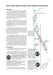
FBW-mode: the vessel is holding it's<br />
heading automatically, when the helm rests<br />
in the center detent. If the helm is deflected<br />
from its center position, a certain rate of turn<br />
will be comm<strong>and</strong>ed by the helm angle. Rudder<br />
movement is fully automatic, to achieve that<br />
rate.<br />
Heading changes in FBW mode may also<br />
be made from the AP-<strong>Display</strong>, like in HDGmode.<br />
The electric helm becomes inactive when<br />
either another helm is activated or an autopilot<br />
mode is selected, or when a separate "Wheel<br />
OFF"-button (see diagram at the left) has<br />
been pressed. The helm <strong>and</strong> the autopilot will<br />
go off, if the Wheel OFF-button is depressed.<br />
Such action will be necessary, if a mechanical<br />
or hydraulic helm or a tiller shall be used for<br />
steering.<br />
SE=22 or 23:<br />
Activation of the helm is only done with the<br />
OFF-button of the associated AP-<strong>Display</strong>. The<br />
rest is identical to SE=21 above.<br />
17