Display Function - Marine Autopilots, Engine Controls and Instruments
Display Function - Marine Autopilots, Engine Controls and Instruments
Display Function - Marine Autopilots, Engine Controls and Instruments

You also want an ePaper? Increase the reach of your titles
YUMPU automatically turns print PDFs into web optimized ePapers that Google loves.
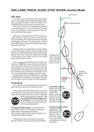
Tecnautic Windsensor<br />
(Use separate instructions for the<br />
PB200 Sensor)<br />
The Wind Sensor must be installed at the<br />
forward end of the mast top <strong>and</strong> its arm must<br />
point forward, so as to give the most accurate<br />
readings, when close hauled or reaching.<br />
The direction of air flow is nevertheless<br />
altered by the presence of the sail underneath.<br />
To avoid the resulting inaccuracies of<br />
true wind direction, speed <strong>and</strong> VMG, the wind<br />
sensor can be mounted on a small mast<br />
about 2 m (7 feet) above the mast top.<br />
The mast cable should be held at the mast<br />
top with a cable tie, in order to relief the plug<br />
from any strain. The cable must not come in<br />
contact with moving halyards.<br />
Operating information: when powering up<br />
the wind display, the anemometer wheel is<br />
driven electrically for a period of two seconds,<br />
to break any eventually present cob webs.<br />
Through deck connector: For easy mast<br />
removal, a sealed connector may be mounted.<br />
Only gold plated contacts are allowed, because<br />
of the low signal level. Silver plated<br />
contacts will also work for some time.<br />
Sensor arm may be bent<br />
forward<br />
Through deck connector (fixed)<br />
Connector installation:<br />
contact- lead<br />
Nr. color signal:<br />
1 white +5 Volts<br />
2 brown 0 Volts<br />
3 yellow wind angle<br />
4 green wind speed<br />
mast<br />
deck<br />
Sealed through deck connector (flying)<br />
(see page 49 for plug installation)<br />
35