Display Function - Marine Autopilots, Engine Controls and Instruments
Display Function - Marine Autopilots, Engine Controls and Instruments
Display Function - Marine Autopilots, Engine Controls and Instruments

Create successful ePaper yourself
Turn your PDF publications into a flip-book with our unique Google optimized e-Paper software.
A5:05 a) Reversible Pump: This function is for<br />
current saving of a Bypass valve. A5=05<br />
gives the lowest current (16% of the<br />
nominal value). For no reduction set<br />
A5=17. A too small current bears a risk<br />
for the valve falling open.<br />
b) Direct driven Proportional Valve:<br />
Minimum rudder speed is set by A5.<br />
A5=02 results in 20% minimum valve<br />
current, A5=17 sets minimum current =<br />
100% (= maximum).<br />
c) with switch over valve or current<br />
regulated servo valve: A5 has no<br />
meaning.<br />
d) with voltage controlled proportional<br />
valve (Danfoss): A5=08 sets the<br />
"flow zero point" signal.<br />
A6:20 (05...28) Rudder travel limit under comm<strong>and</strong><br />
of the Drivebox. See on the left<br />
side, for setting up.<br />
A7:13 (06...31) Magnitude of rudder deflections<br />
for heading corrections. The gain should<br />
be set as high as possible, to enable<br />
powerful rudder deflections, if needed.<br />
However a too high gain could result in<br />
heading oscillations, when the rudder<br />
drive is slow to follow large rudder comm<strong>and</strong>s<br />
(not to be confused with quick<br />
rudder oscillations, see A9)<br />
A8:00 Terminal 1-4: Terminal 7-8:<br />
00 Bypass/Clutch revers. AP-Drive<br />
01 -- --<br />
02 Cool.Fan (1-2) revers. AP-Drive<br />
03 Bow Thruster revers. AP-Drive<br />
04 AP-Valves L/R Bow Thruster<br />
05 Stern Thruster revers. AP-Drive<br />
06 AP-Valves L/R Stern Thruster<br />
07 Bow Thruster Stern Thruster<br />
08 -- Bow Thruster<br />
09 Stern Thruster --<br />
10 Bow Thruster --<br />
11 -- Stern Thruster<br />
12 Stern Thruster Bow Thruster<br />
A9:05 a) (01...10) Stopping distance of the<br />
rudder drive at full speed. Faster drives<br />
need higher numbers. Try the lowest possible<br />
number which is not resulting in<br />
quick rudder oscillations. Note: rudder oscillations<br />
are not to be mistaken for heading<br />
oscillations <strong>and</strong> may be present with<br />
the vessel moored in port, when the autopilot<br />
or servo steering is on.<br />
b) A9 is not applicable for Servo Valves.<br />
c) A9=00 temporary setting for A0*..A8*<br />
AA:12 (06..50) Insert here the maximum boat<br />
speed in knots. Rudder gain will be reduced<br />
linearly with increasing log-speed<br />
(or GPS-speed), so as to bottom out at<br />
50% at the maximum inserted speed.<br />
23<br />
A_:50 (40...60) The rudder center position can<br />
be adjusted (up to +/- 2 degrees) during<br />
installation. A higher number turns<br />
the rudder to starboard.<br />
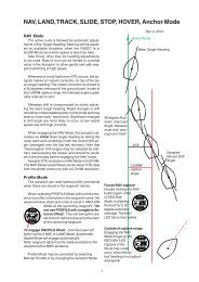
Ac:00 Ac=01 gives automatic intercepts of the<br />
programmed track in NAV mode. Ac=00<br />
offers the freedom (<strong>and</strong> responsibility) for<br />
choosing a suitable intercept angle. An<br />
automatic intercept will nevertheless<br />
start, when the cross track error is less<br />
than 0,030 NM.<br />
A-:00 sets NMEA output from the Drivebox:<br />
A- =00 .. Test data out (ASCII term.)<br />
A- =01 .. Set up flux gate HS8000<br />
A- =02 .. HDM <strong>and</strong> VHW out (8 Hz)<br />
A- =03 .. VHW out (8 Hz)<br />
A- =04 .. test heading instead compass<br />
A- =05 ... CAN-Bus splitter for dual AP<br />
Second group of parameters A0*.. A8*<br />
They are not identical to A0 .. A8. They represent<br />
a different set of parameters. The asterisk<br />
is not shown on the display unit, it is only<br />
used here for explanation. A0*.. A8* are displayed,<br />
when A9 has been set to zero previously.<br />
Otherwise A0 .. A8 will be visible.<br />
A0*:00 St<strong>and</strong>ard setting is 00. Only with proportional<br />
valve set A0*=01.<br />
A1*:00 Set A1*=00 for one single autopilot or<br />
two parallel autopilots on two unconnected<br />
rudders. Set A1*=01 for two alternating<br />
autopilots or two parallel APs<br />
on the same rudder (hydraulic system).<br />
A2*:00 Set A2*=00 when the rudder angle sensor<br />
is connected to the Drivebox. Set<br />
A2*=01 when the rudder angle sensor<br />
is connected remotely to the CAN-bus,<br />
for example to a display unit.<br />
A3*:00 Type of rudder sensor: A3*=00 for 90-<br />
degree potentiometer. A3* must be set<br />
to 01 for 340-degree rudder sensor (requires<br />
Drivebox 40L or 08L hardware).<br />
A4*:00 Only for two pumps working on the<br />
same hydraulic system (assisting each<br />
other), set A4*=01. With Danfoss valves,<br />
use A4* to reverse the output signal.<br />
A5*:00 Set A5*=01 for voltage controlled (Danfoss)<br />
proportional valves.<br />
A6*:00 (0..16) Basic spread angle of two separately<br />
steered drives in Docking-Mode.<br />
A7*:00 A7*=01 enables the Docking-Mode<br />
without the FADEC system installed<br />
A8*:00 A8*=01 makes AP1 (port drive) a permanent<br />
SLAVE, even when AP2 (stbd<br />
drive, the master) is OFF. The manual<br />
steering system should be connected<br />
only to the starboard drive.