Display Function - Marine Autopilots, Engine Controls and Instruments
Display Function - Marine Autopilots, Engine Controls and Instruments
Display Function - Marine Autopilots, Engine Controls and Instruments
Create successful ePaper yourself
Turn your PDF publications into a flip-book with our unique Google optimized e-Paper software.
Use the left <strong>and</strong> right (lower) buttons to set<br />
the desired display type:<br />
di:00 Multi <strong>Function</strong> <strong>Display</strong>. All display<br />
functions can be activated on a<br />
display with di=00 (Log, Wind,<br />
Compass etc.)<br />
di:01 Autopilot <strong>Display</strong> (with six push<br />
buttons)<br />
di:02 Compass <strong>Display</strong> with Autopilot<br />
<strong>Function</strong> (three buttons)<br />
di:03 Trim Flap <strong>Display</strong> (with six push<br />
buttons)<br />
<strong>Display</strong> <strong>Function</strong>:<br />
This selection defines, which function will<br />
be available on a Multi <strong>Function</strong> <strong>Display</strong> (i.e.<br />
any display with di=00, independent of the<br />
printing on the display bezel).<br />
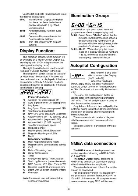
The right (lower) button is used to scroll<br />
from one "<strong>Function</strong> Number" to the next.<br />
The left (lower) button is used to "activate"<br />
or "deactivate" the function. A function has<br />
been activated (can be displayed), if the function<br />
number is steady. A function has been<br />
deactivated (cannot be displayed), if the function<br />
number is blinking:<br />
Primary <strong>Function</strong>s:<br />
F0 Autopilot Fail Codes (page 50)<br />
11 Gyro signal monitor (for testing only)<br />
20 Log Speed<br />
24 Log Speed 15 sec average (no LED)<br />
23 Trip Distance (resettable)<br />
91 NAV: GPS GND-speed <strong>and</strong> GND track<br />
30 Apparent Wind (+/- 180 degrees LED)<br />
31 Apparent Wind (exp<strong>and</strong>ed LED)<br />
32 Apparent Wind (0..359 degrees)<br />
34 True Wind angle <strong>and</strong> speed<br />
28 Rig Load Sensor<br />
61 Heading Hold (with LED pointer)<br />
62 Magnetic Heading (no LED)<br />
75 Depth<br />
Secondary <strong>Function</strong>s:<br />
33 Mast Angle (for rotating mast)<br />
35 Magnetic Wind (direction <strong>and</strong> speed)<br />
36 VMG<br />
64 Rate of Turn (deg / sec)<br />
82 Water Temperature<br />
83 Timer<br />
21 Average Trip Speed / Trip Distance<br />
22 Total Log Distance (cannot be reset)<br />
90 NAV: Course, XTE, Dist., Time to WP<br />
92 Selected Boat SPD <strong>and</strong> engine rpm<br />
77 Depth Unit Selection (meters or feet)<br />
81 Voltmeter<br />
Note: for ease of use, activate only the<br />
necessary functions<br />
Illumination Group:<br />
Use the left or right push button to set the<br />
group number of every single display unit:<br />
Gr:00 Group Zero = "Master"; When the illumination<br />
level (brightness) is set on a<br />
display with group number zero, all<br />
displays will follow in brightness, independent<br />
of their own group number.<br />
Gr:01 .. Gr:15 When changing the brightness<br />
on a display with group numbers<br />
1 to 15, only those displays with the<br />
same group number will follow.<br />
Autopilot Configuration<br />
This function is only available<br />
on an Autopilot <strong>Display</strong><br />
(di=01 or di=02).<br />
When that reading is<br />
shown, apply briefly the left or right (lower)<br />
button, to switch to the first Autopilot Parameter<br />
"A0". Be careful not to modify A0 inadvertently!<br />
Thereafter the middle (lower) button is<br />
used to scroll to the remaining parameters<br />
"A1" to "A-". The left or right button is used to<br />
alter the respective parameter.<br />
Only A0 <strong>and</strong> A6 should be modifyed by the<br />
customer during installation. Other parameters<br />
should only be altered after consulting with<br />
the manufacturer.<br />
The customer should receive a diagram<br />
with the recommended parameters for his<br />
vessel.<br />
See page 22/23 for significance of the parameters.<br />
NMEA data connection<br />
The NMEA Input of the display unit can<br />
receive signals conforming to NMEA-0183-<br />
V1.5 <strong>and</strong> V.2.0<br />
The NMEA Output signal conforms to<br />
NMEA-0183 Version 2.x (symmetric signal)<br />
with a 5 Volts differential amplitude.<br />
Therefore both version 1.5 <strong>and</strong> 2.x receivers<br />
can be connected.<br />
For single pole (Version 1.5) data receivers,<br />
you should connect Tecnautic"Out-A" to<br />
"Data-IN" of the receiver. All equipment must<br />
have a common supply GND in this case.<br />
27


