Display Function - Marine Autopilots, Engine Controls and Instruments
Display Function - Marine Autopilots, Engine Controls and Instruments
Display Function - Marine Autopilots, Engine Controls and Instruments

You also want an ePaper? Increase the reach of your titles
YUMPU automatically turns print PDFs into web optimized ePapers that Google loves.
Rudder Angle Sensor<br />
Installation<br />
St<strong>and</strong>ard version for mounting on<br />
the cylinder piston rod<br />
The rudder angle<br />
sensor must pick up<br />
the rudder movement<br />
without any<br />
play.<br />
Piston Rod of hydraulic<br />
cylinder<br />
ATTENTION: The hook length must be<br />
adjusted so as not to interfere with the cylinder,<br />
when the piston is fully retracted!<br />
To adjust the hook length, proceed as follows:<br />
1. Remove the lid on top of the Sensor<br />
2. Unscrew the hook<br />
3. Adjust the hook length <strong>and</strong> tighten the<br />
hook screws<br />
4. Close the lid<br />
The hook must be bent so as to guarantee<br />
a firm grip of the piston rod, even when it is<br />
moving vertically! There must be absolutely<br />
no play.<br />
WARNING: make sure the hook does not<br />
interfere with the rudder arm at full rudder<br />
deflection!!!<br />
The sensor is supplied with a hook. The<br />
hook is properly bent for a piston rod of 16<br />
mm (5/8") diameter.<br />
A hole (6,5 mm / 2/8" diameter <strong>and</strong> 10 mm<br />
/ 3/8" deep) should be drilled along the axis of<br />
the bolt. A second hole with a 3 mm (1/8")<br />
thread is required to fix the shaft of the potentiometer<br />
in the bolt. For different conditions,<br />
the wire hook may be bent as required.<br />
If the linear drive unit has been supplied by<br />
TECNAUTIC, the bolt with properly drilled<br />
holes is provided by the factory.<br />
Checking the Sensor after the installation<br />
<strong>and</strong> setup procedure has<br />
been completed<br />
Do not proceed with this test before completing<br />
the initial installation <strong>and</strong> setup (p.22)!<br />
Switch on the SERVO mode, if an<br />
electronic steering wheel is installed <strong>and</strong> turn<br />
the wheel to the middle position.<br />
Or, if there is no electronic steering wheel<br />
available, have the boat moored firmly, so as<br />
not to change its heading. Place the rudder<br />
amidships <strong>and</strong> engage the autopilot HDG<br />
mode. Verify the displayed heading to be stable,<br />
before engaging the autopilot.<br />
The rudder should be steady at this stage.<br />
Now try to apply very light sideways force<br />
with your finger tip onto the hook of the rudder<br />
angle sensor. If there is play, the rudder will<br />
move. Eliminate the play!<br />
Play leads to rudder oscillations <strong>and</strong> inaccurate<br />
steering.<br />
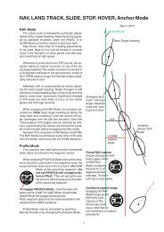
Conventional Rudder Sensor Installation<br />
In case of an existing rudder actuator, it<br />
might be easier, to install the sensor in a conventional<br />
way. Tecnautic recommends its<br />
"sealed rudder sensor"<br />
(part nr. 23 00 03) for<br />
that purpose.<br />
There is no requirement<br />
on the orientation of the sensor.<br />
The sensor arm A <strong>and</strong> the effective<br />
arm B at the rudder must be of equal length.<br />
Only with stern drives A can be bigger than B,<br />
to achieve larger rudder deflections.<br />
Symmetric conditions are required in the<br />
case of two independent rudders or stern<br />
drives.<br />
NOTE: there must be a 90 degrees angle<br />
between the arm <strong>and</strong> the connecting rod,<br />
when the rudder is centered.<br />
A<br />
Make sure: A = B<br />
Rudder Centered:<br />
B<br />
43