User Guide: NanoLC Ultra® System Integration Test - Eksigent
User Guide: NanoLC Ultra® System Integration Test - Eksigent
User Guide: NanoLC Ultra® System Integration Test - Eksigent

Create successful ePaper yourself
Turn your PDF publications into a flip-book with our unique Google optimized e-Paper software.
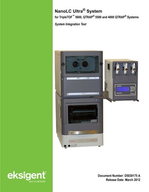
<strong>NanoLC</strong> Ultra ® <strong>System</strong><br />
for TripleTOF 5600, QTRAP ® 5500 and 4000 QTRAP ® <strong>System</strong>s<br />
<strong>System</strong> <strong>Integration</strong> <strong>Test</strong><br />
Document Number: D5030175 A<br />
Release Date: March 2012
This document is provided to customers who have purchased<br />
AB Sciex equipment to use in the operation of such AB Sciex<br />
equipment. This document is copyright protected and any reproduction<br />
of this document or any part of this document is strictly prohibited,<br />
except as AB Sciex may authorize in writing.<br />
Software that may be described in this document is furnished under a<br />
license agreement. It is against the law to copy, modify, or distribute<br />
the software on any medium, except as specifically allowed in the<br />
license agreement. Furthermore, the license agreement may prohibit<br />
the software from being disassembled, reverse engineered, or<br />
decompiled for any purpose.<br />
Portions of this document may make reference to other manufacturers<br />
and/or their products, which may contain parts whose names are<br />
registered as trademarks and/or function as trademarks of their<br />
respective owners. Any such use is intended only to designate those<br />
manufacturers' products as supplied by AB Sciex for incorporation into<br />
its equipment and does not imply any right and/or license to use or<br />
permit others to use such manufacturers' and/or their product names<br />
as trademarks.<br />
AB Sciex makes no warranties or representations as to the fitness of<br />
this equipment for any particular purpose and assumes no<br />
responsibility or contingent liability, including indirect or consequential<br />
damages, for any use to which the purchaser may put the equipment<br />
described herein, or for any adverse circumstances arising therefrom.<br />
For research use only. Not for use in diagnostic procedures.<br />
The trademarks mentioned herein are the property of<br />
AB Sciex Pte. Ltd. or their respective owners. <strong>Eksigent</strong> is a division of<br />
AB Sciex, LLC.<br />
AB SCIEX is being used under license.<br />
<strong>Eksigent</strong><br />
5875 Arnold Road, Dublin, CA 94568.<br />
AB Sciex LP is ISO 9001 registered.<br />
© 2012 AB SCIEX.<br />
Printed in Canada.
Contents<br />
Foreword. . . . . . . . . . . . . . . . . . . . . . . . . . . . . . . . . . . . . . . . . . . . . . . . . . . . . . . . . . 5<br />
General Safety Information . . . . . . . . . . . . . . . . . . . . . . . . . . . . . . . . . . . . . . . . . .5<br />
Symbols and Conventions . . . . . . . . . . . . . . . . . . . . . . . . . . . . . . . . . . . . . . . . . .5<br />
Safety Instructions . . . . . . . . . . . . . . . . . . . . . . . . . . . . . . . . . . . . . . . . . . . . . . . . .6<br />
Qualified Personnel . . . . . . . . . . . . . . . . . . . . . . . . . . . . . . . . . . . . . . . . . . . . . . . .8<br />
Equipment Use and Modification . . . . . . . . . . . . . . . . . . . . . . . . . . . . . . . . . . . . .8<br />
Mains Supply . . . . . . . . . . . . . . . . . . . . . . . . . . . . . . . . . . . . . . . . . . . . . . . . . . .9<br />
Environmental Conditions . . . . . . . . . . . . . . . . . . . . . . . . . . . . . . . . . . . . . . . . .9<br />
Instrument Disposal (Waste Electrical and Electronic Equipment) . . . . . . . . .10<br />
Regulatory Compliance . . . . . . . . . . . . . . . . . . . . . . . . . . . . . . . . . . . . . . . . . . . .10<br />
Additional Documentation . . . . . . . . . . . . . . . . . . . . . . . . . . . . . . . . . . . . . . . . . .11<br />
Technical Support . . . . . . . . . . . . . . . . . . . . . . . . . . . . . . . . . . . . . . . . . . . . . . . .11<br />
Chapter 1 LC/MS <strong>System</strong> Configuration <strong>Test</strong>—<br />
AB SCIEX TripleTOF 5600 <strong>System</strong> . . . . . . . . . . . . . . . . . . . . . . . . . . . . . . . . . . 13<br />
Create the Methods and Batch for the <strong>System</strong> Functional <strong>Test</strong> . . . . . . . . . . . . .14<br />
Create the Acquisition Methods and Batch—Functional <strong>Test</strong> . . . . . . . . . . . . .14<br />
Create the LC Methods . . . . . . . . . . . . . . . . . . . . . . . . . . . . . . . . . . . . . . . . . .16<br />
Create the Acquisition Method in the Analyst® TF Software . . . . . . . . . . . . . .21<br />
Create the Methods and Batch for the <strong>System</strong> Performance <strong>Test</strong> . . . . . . . . . . .25<br />
Create the Acquisition Methods and Batch—Performance <strong>Test</strong>s . . . . . . . . . .25<br />
Create the LC Method . . . . . . . . . . . . . . . . . . . . . . . . . . . . . . . . . . . . . . . . . . .26<br />
Specify the Acquisition Method in the Analyst TF Software . . . . . . . . . . . . . .31<br />
Prepare the <strong>System</strong> for <strong>Test</strong>ing . . . . . . . . . . . . . . . . . . . . . . . . . . . . . . . . . . . . .34<br />
Prepare the Solution and Dilution . . . . . . . . . . . . . . . . . . . . . . . . . . . . . . . . . .34<br />
Condition the <strong>System</strong> . . . . . . . . . . . . . . . . . . . . . . . . . . . . . . . . . . . . . . . . . . .35<br />
Verify <strong>System</strong> Readiness . . . . . . . . . . . . . . . . . . . . . . . . . . . . . . . . . . . . . . . .36<br />
Perform the <strong>System</strong> Functional <strong>Test</strong> . . . . . . . . . . . . . . . . . . . . . . . . . . . . . . . . . .37<br />
Perform the <strong>System</strong> Performance <strong>Test</strong> . . . . . . . . . . . . . . . . . . . . . . . . . . . . . . . .42<br />
Troubleshoot Peak Problems . . . . . . . . . . . . . . . . . . . . . . . . . . . . . . . . . . . . . . .46<br />
Create a Backup of the EKSettings.reg File . . . . . . . . . . . . . . . . . . . . . . . . . . . .49<br />
<strong>Test</strong> Results—TripleTOF 5600 Instruments . . . . . . . . . . . . . . . . . . . . . . . . . . . .50<br />
Chapter 2 LC/MS <strong>System</strong> Configuration <strong>Test</strong>—<br />
AB SCIEX QTRAP ® 5500 <strong>System</strong> . . . . . . . . . . . . . . . . . . . . . . . . . . . . . . . . . . . . . 51<br />
Create the Methods and Batch for the <strong>System</strong> Functional <strong>Test</strong> . . . . . . . . . . . . .52<br />
Create the Acquisition Methods and Batch—Functional <strong>Test</strong> . . . . . . . . . . . . .52<br />
Create the LC Methods . . . . . . . . . . . . . . . . . . . . . . . . . . . . . . . . . . . . . . . . . .54<br />
Create the Acquisition Method in the Analyst® Software . . . . . . . . . . . . . . . .59<br />
Create the Methods and Batch for the <strong>System</strong> Performance <strong>Test</strong> . . . . . . . . . . .63<br />
Create the Acquisition Methods and Batch—Performance <strong>Test</strong>s . . . . . . . . . .63<br />
Create the LC Methods . . . . . . . . . . . . . . . . . . . . . . . . . . . . . . . . . . . . . . . . . .64<br />
Specify the Acquisition Method in the Analyst Software . . . . . . . . . . . . . . . . .69<br />
Prepare the <strong>System</strong> for <strong>Test</strong>ing . . . . . . . . . . . . . . . . . . . . . . . . . . . . . . . . . . . . .73<br />
Prepare the Solution and Dilution . . . . . . . . . . . . . . . . . . . . . . . . . . . . . . . . . .73<br />
<strong>System</strong> <strong>Integration</strong> <strong>Test</strong><br />
D5030175 A<br />
<strong>NanoLC</strong> Ultra ® <strong>System</strong><br />
3 of 124
Contents<br />
Condition the <strong>System</strong> . . . . . . . . . . . . . . . . . . . . . . . . . . . . . . . . . . . . . . . . . . .74<br />
Verify <strong>System</strong> Readiness . . . . . . . . . . . . . . . . . . . . . . . . . . . . . . . . . . . . . . . .74<br />
Perform the <strong>System</strong> Functional <strong>Test</strong> . . . . . . . . . . . . . . . . . . . . . . . . . . . . . . . . . .76<br />
Perform the <strong>System</strong> Performance <strong>Test</strong> . . . . . . . . . . . . . . . . . . . . . . . . . . . . . . . .78<br />
Troubleshoot Peak Problems . . . . . . . . . . . . . . . . . . . . . . . . . . . . . . . . . . . . . . .80<br />
Create a Backup of the EKSettings.reg File . . . . . . . . . . . . . . . . . . . . . . . . . . . .82<br />
<strong>Test</strong> Results—QTRAP 5500 Instruments . . . . . . . . . . . . . . . . . . . . . . . . . . . . . .83<br />
Chapter 3 LC/MS <strong>System</strong> Configuration <strong>Test</strong>—<br />
AB SCIEX 4000 QTRAP ® <strong>System</strong> . . . . . . . . . . . . . . . . . . . . . . . . . . . . . . . . . . . . . 85<br />
Create the Methods and Batch for the <strong>System</strong> Functional <strong>Test</strong> . . . . . . . . . . . . .86<br />
Create the Acquisition Method and Batch—Functional <strong>Test</strong> . . . . . . . . . . . . . .86<br />
Create the LC Methods . . . . . . . . . . . . . . . . . . . . . . . . . . . . . . . . . . . . . . . . . .88<br />
Create the Acquisition Method in the Analyst® Software . . . . . . . . . . . . . . . .93<br />
Create the Methods and Batch for the <strong>System</strong> Performance <strong>Test</strong> . . . . . . . . . . .97<br />
Create the Acquisition Methods and Batch—Performance <strong>Test</strong>s . . . . . . . . . .97<br />
Create the LC Methods . . . . . . . . . . . . . . . . . . . . . . . . . . . . . . . . . . . . . . . . . .98<br />
Create the Acquisition Method in the Analyst Software . . . . . . . . . . . . . . . . .103<br />
Prepare the <strong>System</strong> for <strong>Test</strong>ing . . . . . . . . . . . . . . . . . . . . . . . . . . . . . . . . . . . .107<br />
Prepare the Solution and Dilution . . . . . . . . . . . . . . . . . . . . . . . . . . . . . . . . .107<br />
Condition the <strong>System</strong> . . . . . . . . . . . . . . . . . . . . . . . . . . . . . . . . . . . . . . . . . .108<br />
Verify <strong>System</strong> Readiness . . . . . . . . . . . . . . . . . . . . . . . . . . . . . . . . . . . . . . .108<br />
Perform the <strong>System</strong> Functional <strong>Test</strong> . . . . . . . . . . . . . . . . . . . . . . . . . . . . . . . . .110<br />
Perform the <strong>System</strong> Performance <strong>Test</strong> . . . . . . . . . . . . . . . . . . . . . . . . . . . . . . .112<br />
Troubleshoot Peak Problems . . . . . . . . . . . . . . . . . . . . . . . . . . . . . . . . . . . . . .114<br />
Create a Backup of the EKSettings.reg File . . . . . . . . . . . . . . . . . . . . . . . . . . .116<br />
<strong>Test</strong> Results—4000 QTRAP Instruments . . . . . . . . . . . . . . . . . . . . . . . . . . . . .117<br />
Appendix A <strong>System</strong> Calibration . . . . . . . . . . . . . . . . . . . . . . . . . . . . . . . . . . . . .119<br />
Prepare the [Glu 1 ]-Fibrinopeptide B Dilution . . . . . . . . . . . . . . . . . . . . . . . . . . .119<br />
Edit the Calibration Reference Table for [Glu1]-Fibrinopeptide B . . . . . . . . . . .120<br />
Calibrate the TOF MS Scan Mode . . . . . . . . . . . . . . . . . . . . . . . . . . . . . . . . . .121<br />
Calibrate the TOF MS/MS for High Sensitivity and High Resolution<br />
Product Ion Modes . . . . . . . . . . . . . . . . . . . . . . . . . . . . . . . . . . . . . . . . . . . . . .122<br />
<strong>NanoLC</strong> Ultra ® <strong>System</strong><br />
4 of 124<br />
<strong>System</strong> <strong>Integration</strong> <strong>Test</strong><br />
D5030175 A
Foreword<br />
This foreword contains general safety-related information, describes the symbols and<br />
conventions used in the documentation, and provides regulatory compliance information. It also<br />
describes potential hazards and associated warnings for the system, and the precautions that<br />
should be taken to minimize the hazards. In addition to this foreword, refer to the Site Planning<br />
<strong>Guide</strong> for site requirements.<br />
General Safety Information<br />
Before operating any instrument, become familiar with its operation and with the potential<br />
hazards. To prevent personal injury or instrument damage, read, understand, and obey all safety<br />
precautions. Warnings in this document and labels on the device are shown with international<br />
symbols. Failure to heed these warnings could result in serious injury.<br />
This safety information is intended to supplement federal, state or provincial, and local<br />
environmental health and safety (EHS) regulations. The information provided covers instrumentrelated<br />
safety with regard to the operation of the device. It does not cover every safety procedure<br />
that should be practised. Ultimately, you and your organization are responsible for compliance<br />
with federal, state or provincial, and local EHS regulations and for maintaining a safe laboratory<br />
environment.<br />
For more information, refer to the appropriate laboratory reference material and standard<br />
operating procedures.<br />
Symbols and Conventions<br />
The following conventions may be used throughout the guide.<br />
DANGER! Danger signifies an action which leads to severe injury or death.<br />
WARNING! Personal Injury Hazard: A warning indicates an operation that could<br />
cause personal injury if precautions are not followed.<br />
WARNING! Electric Shock Hazard: This symbol indicates a warning of electrical<br />
shock hazard. Read the warning and follow all precautions before performing any<br />
operation described in the guide. Failure to do so can result in serious injury.<br />
WARNING! Burn Hazard: This symbol indicates a warning of potential burns<br />
from hot surfaces. Read the warning and follow all precautions before performing<br />
any operation described in the guide. Failure to do so can result in serious injury.<br />
<strong>System</strong> <strong>Integration</strong> <strong>Test</strong><br />
D5030175 A<br />
<strong>NanoLC</strong> Ultra ® <strong>System</strong><br />
5 of 124
i<br />
Foreword<br />
WARNING! Biohazard: This symbol indicates a warning of biohazardous<br />
materials. Read the warning and follow all precautions before performing any<br />
operation described in the guide. Failure to do so can result in serious injury.<br />
Caution: A caution indicates an operation that could cause damage to the instrument or<br />
loss of data if precautions are not followed.<br />
Tip! Provides useful information that helps apply the techniques and procedures in<br />
the text for a specific need, and provides shortcuts, but is not essential to the completion<br />
of a procedure.<br />
Note: A note emphasizes significant information in a procedure or description.<br />
Safety Instructions<br />
The following safety instructions apply to the <strong>NanoLC</strong> Ultra system:<br />
WARNING! Potential Operator Injury: Use of this equipment in a manner not<br />
approved by the manufacturer may inhibit its safety protection.<br />
Caution: Changes or modifications to this unit not expressly approved by the<br />
manufacturer could void the instrument warranty and render the system inoperable.<br />
WARNING! Electrical Shock Hazard: Only use fuses of the type and current<br />
rating specified. Do not use repaired fuses or by-pass the fuse holder.<br />
WARNING! Electrical Shock Hazard: The supplied power cord must be used with<br />
a power outlet containing a protective ground contact.<br />
WARNING! Biohazard: When replacing tubing or fittings on the ekspert microLC<br />
200 system, exposure to solvents may occur. It is therefore recommended that<br />
appropriate safety procedures be followed and personal protective equipment be<br />
used, according to the applicable Material Safety Data Sheets supplied by the<br />
solvent vendor.<br />
WARNING! Electrical Shock Hazard: Do not change the external or internal<br />
grounding connections. Tampering with or disabling these connections could<br />
create a safety hazard and/or damage the system. The instrument, as shipped, is<br />
properly grounded in accordance with normal safety regulations.<br />
<strong>NanoLC</strong> Ultra ® <strong>System</strong><br />
6 of 124<br />
<strong>System</strong> <strong>Integration</strong> <strong>Test</strong><br />
D5030175 A
Foreword<br />
WARNING! Potential <strong>System</strong> Damage: Do not turn the system on if you suspect<br />
that it has incurred any kind of electrical damage. Instead, disconnect the power<br />
cord and evaluate the system.<br />
WARNING! Potential <strong>System</strong> Damage: Electrical damage may have occurred if<br />
any part of the system shows visible signs of damage, exposure to liquids or of<br />
having been transported under severe stress.<br />
WARNING! Electrical Shock Hazard: Continue to exercise caution as capacitors<br />
inside the system may still be charged even after the system has been turned off.<br />
WARNING! Electrical Shock Hazard: Disconnect power cords from the power<br />
supply before attempting any type of maintenance.<br />
WARNING! Electrical Shock Hazard: The combination of the pump and<br />
autosampler with a LC/MS system may require additional safety measures as<br />
described by AB SCIEX. See the mass spectrometer Safety <strong>Guide</strong> for instructions<br />
for the safe grounding on the LC/MS system.<br />
WARNING! Electrical Shock Hazard: Use a grounding cable connected between<br />
the injection valve's sample loop and an appropriate grounding point at the<br />
LC/MS source. This supplementary grounding will reinforce the safety<br />
configuration specified by AB SCIEX.<br />
WARNING! Potential <strong>System</strong> Damage: Damage can result if the system is stored<br />
for prolonged periods under extreme conditions (for example, subjected to heat,<br />
water, etc.).<br />
WARNING! Environmental Hazard: Do not allow flammable and/or toxic solvents<br />
to accumulate. Follow a regulated, approved waste disposal program. Never<br />
dispose of flammable and/or toxic solvents into a municipal sewage system.<br />
WARNING! Potential <strong>System</strong> Damage: To avoid damaging electrical parts, do not<br />
disconnect an electrical assembly while power is applied to the system. Once the<br />
power is turned off, wait approximately 30 seconds before disconnecting an<br />
assembly.<br />
WARNING! Potential <strong>System</strong> Damage: The system contains a number of<br />
sensitive electronic components that may be damaged if exposed to excessive<br />
line voltage fluctuations and/or power surges.<br />
<strong>System</strong> <strong>Integration</strong> <strong>Test</strong><br />
D5030175 A<br />
<strong>NanoLC</strong> Ultra ® <strong>System</strong><br />
7 of 124
Foreword<br />
WARNING! Potential Operator Injury: To avoid injury during operation, keep<br />
hands and loose objects away from the autosampler arm and syringe assembly.<br />
WARNING! Potential Operator Injury: Use caution when working with any<br />
polymeric tubing under pressure:<br />
– Always wear proper eye protection when near pressurized polymer tubing.<br />
– Do not use polymer tubing that has been severely stressed or kinked.<br />
– Do not use polymer tubing, in particular PEEK or DuPont Tefzel tubing, with<br />
tetrahydrofuran (THF), dimethylsulfoxide (DMSO), chlorinated organic solvents,<br />
concentrated mineral acids, such as nitric, phosphoric or sulfuric acids, or any<br />
related compounds.<br />
WARNING! Puncture Hazard: Do not operate the autosampler without the safety<br />
shield properly installed.<br />
Caution: Potential <strong>System</strong> Damage: An on-board lithium battery maintains the<br />
autosampler firmware when the instrument is turned off. It should only be replaced by a<br />
factory-authorized service engineer.<br />
Caution: Potential Data Corruption: When you use the HTC-xt PAL autosampler for<br />
chromatographic analyses and observe a change in the retention of a particular<br />
compound, the resolution between two compounds or peak shapes, immediately<br />
determine the reason for the changes. Do not rely on the analytical results until the cause<br />
of the change is determined.<br />
Qualified Personnel<br />
After installing the system, the FSE (Field Service Employee) uses the Customer Familiarization<br />
Checklist to train the customer on system operation, cleaning, and basic maintenance. Only<br />
AB SCIEX trained personnel shall operate and maintain the equipment. Equipment installation<br />
and service shall only be conducted by AB SCIEX Field Service Employees. Contact an AB<br />
SCIEX FSE for more information.<br />
Equipment Use and Modification<br />
Use the system indoors in a laboratory that complies with the environmental conditions<br />
recommended in the system Site Planning <strong>Guide</strong>. If the system is used in an environment or in a<br />
manner not prescribed by AB SCIEX, the protection provided by the equipment can be impaired.<br />
Unauthorized modification or operation of the system may cause personal injury and equipment<br />
damage, and may void the warranty. Contact an AB SCIEX representative for more information<br />
on servicing the system.<br />
<strong>NanoLC</strong> Ultra ® <strong>System</strong><br />
8 of 124<br />
<strong>System</strong> <strong>Integration</strong> <strong>Test</strong><br />
D5030175 A
Foreword<br />
Mains Supply<br />
WARNING! Electrical Shock Hazard: Use only qualified personnel for the<br />
installation of all electrical supplies and fixtures, and make sure that all<br />
installations adhere to local regulations.<br />
For information on system electrical specifications, refer to the Site Planning <strong>Guide</strong>.<br />
Protective Conductor<br />
The mains supply should include a correctly installed protective earth conductor that must be<br />
installed or checked by a qualified electrician before connecting the instrument.<br />
Do not intentionally interrupt the protective conductor. Any interruption of the protective<br />
conductor is likely to make the installation dangerous.<br />
Environmental Conditions<br />
Use qualified personnel for the installation of electrical mains, heating, ventilation, and plumbing<br />
supplies and fixtures. Make sure that all installations follow local bylaws and biohazard<br />
regulations. For more information about the required environmental conditions for the system,<br />
refer to the Site Planning <strong>Guide</strong> for the instrument.<br />
WARNING! Explosion Hazard: The instrument is not designed for operation in an<br />
explosive environment. Do not operate the instrument in an environment<br />
containing explosive gases.<br />
WARNING! Asphyxiation Hazard: The use of instruments without adequate<br />
ventilation to outside air may constitute a health hazard. In addition, certain<br />
procedures required during the operation of the instrument may cause gases to<br />
be discharged into the exhaust stream; under these conditions, inadequate<br />
ventilation may result in serious injury. Take extreme care to vent exhaust gases<br />
properly.<br />
WARNING! Toxic Chemical Hazard: Make sure that the source exhaust system is<br />
properly connected, particularly if samples containing toxic or highly volatile<br />
chemicals or solvents are being analyzed. A minimum 20% positive air flow into<br />
the laboratory is required.<br />
WARNING! Biohazard: This instrument or any part is not intended to act as a<br />
biological containment safety cabinet. For biohazardous material use, always<br />
apply local regulations for hazard assessment, control, and handling.<br />
<strong>System</strong> <strong>Integration</strong> <strong>Test</strong><br />
D5030175 A<br />
<strong>NanoLC</strong> Ultra ® <strong>System</strong><br />
9 of 124
Foreword<br />
Instrument Disposal (Waste Electrical and Electronic<br />
Equipment)<br />
Do not dispose of system components or subassemblies, including computer parts, as unsorted<br />
municipal waste. Follow local municipal waste ordinances for proper disposal provisions to<br />
reduce the environmental impact of WEEE (waste, electrical, and electronic equipment). To<br />
make sure that you safely dispose of this equipment, contact an FSE for instructions.<br />
European Union customers: Contact a local AB SCIEX Customer Service office for<br />
complimentary equipment pick-up and recycling.<br />
Regulatory Compliance<br />
This system complies with the standards and regulations listed in this section. Applicable labels<br />
have been affixed to the system.<br />
Canada<br />
Europe<br />
• Safety—CSA 61010-1<br />
• Low Voltage Directive 2006 / 95 / EC<br />
• Electromagnetic Compatibility—61326-1 EN 55011 Class A, EMC Directive 2004 /<br />
108 / EC<br />
• Safety—EN 61010-1<br />
For more information on EU compliance, see the Declaration of Conformance included with the<br />
system.<br />
International<br />
• Electromagnetic Compatibility—CISPR 11 Class A, IEC 61326-1<br />
• Safety—IEC 61010-1<br />
United States<br />
• Safety—UL 61010-1<br />
<strong>NanoLC</strong> Ultra ® <strong>System</strong><br />
10 of 124<br />
<strong>System</strong> <strong>Integration</strong> <strong>Test</strong><br />
D5030175 A
Foreword<br />
Additional Documentation<br />
• <strong>NanoLC</strong> Ultra ® <strong>System</strong> Operator’s Manual—Printed and electronic copies are<br />
included with the system<br />
• <strong>Eksigent</strong>® Control Software <strong>User</strong> <strong>Guide</strong>—installed with the <strong>Eksigent</strong> control software<br />
• Analyst ® Software Getting Started <strong>Guide</strong>—installed with the Analyst software<br />
Technical Support<br />
AB SCIEX and its representatives maintain a staff of fully-trained service and technical<br />
specialists located throughout the world. They can answer questions about the instrument or any<br />
technical issues that may arise. For more information, visit the web site at www.absciex.com.<br />
<strong>System</strong> <strong>Integration</strong> <strong>Test</strong><br />
D5030175 A<br />
<strong>NanoLC</strong> Ultra ® <strong>System</strong><br />
11 of 124
Foreword<br />
<strong>NanoLC</strong> Ultra ® <strong>System</strong><br />
12 of 124<br />
<strong>System</strong> <strong>Integration</strong> <strong>Test</strong><br />
D5030175 A
LC/MS <strong>System</strong> Configuration <strong>Test</strong>—<br />
AB SCIEX TripleTOF 5600 <strong>System</strong><br />
1<br />
This chapter describes the steps for preparing and performing LC/MS system configuration tests<br />
for the <strong>NanoLC</strong> Ultra ® system configured with the cHiPLC ® Nanoflex system (or external<br />
ChromXP column) and the AB SCIEX TripleTOF 5600 instrument.<br />
Note: The tests in this chapter are written for Gradient 2 as the low-flow channel. If this<br />
is not true for your system (for example, if you have a 1D or 1D+ system), then make<br />
appropriate changes throughout the tests.<br />
The tests in this chapter are divided as follows:<br />
• Fast test to condition the column and determine the functional status of the system.<br />
See Create the Methods and Batch for the <strong>System</strong> Functional <strong>Test</strong> for details.<br />
Perform these tests after completing the NanoSpray ® ion source infusion tests in<br />
order to first confirm the spray performance of the tip. Refer to the NanoSpray ® Ion<br />
Source Operator <strong>Guide</strong> for more information.<br />
• Longer test to determine the performance level of the instrument for proteomics<br />
applications such as protein identification and quantification. See Create the<br />
Methods and Batch for the <strong>System</strong> Performance <strong>Test</strong> for details.<br />
These tests can be used as a measure of the <strong>NanoLC</strong> Ultra system performance in<br />
isolation of performance of the other components. Results from these tests can<br />
become the baseline performance for the system and can be performed regularly<br />
and used as a system quality control test in the future.<br />
Approximate time required:<br />
1. Create the methods and batch: 45 minutes<br />
2. Prepare the system for testing: 3-4 hours<br />
3. Perform the test.<br />
i. <strong>System</strong> functional test: 90 minutes<br />
ii. <strong>System</strong> performance test: 180 minutes<br />
Recommended solvents can be ordered from VWR:<br />
• Burdick and Jackson acetonitrile with 0.1% formic acid, P/N BJLC441-1.0<br />
• Burdick and Jackson water with 0.1% formic acid, P/N BJLC452-1.0<br />
Required materials for a Nanoflex system installation:<br />
• Reverse phase cHiPLC column (75 µm x 15 cm ChromXP C18-CL 3 µm 120 Å)<br />
• cHiPLC trap (200 µm x 0.5 mm ChromXP C18-CL 3 µm 120 Å)<br />
• LC/MS Peptide/Protein Mass Standards Kit (P/N 4368624)<br />
Note: Make sure that the Nanoflex system is in the Load position before beginning<br />
these tests.<br />
<strong>System</strong> <strong>Integration</strong> <strong>Test</strong><br />
D5030175 A<br />
<strong>NanoLC</strong> Ultra ® <strong>System</strong><br />
13 of 124
LC/MS <strong>System</strong> Configuration <strong>Test</strong>— AB SCIEX TripleTOF 5600 <strong>System</strong><br />
Required materials for an external column installation:<br />
• Reversed phase ChromXP nanoLC column (75 µm ID x 15 cm, ChromXP C18 3 µm<br />
120 Å, P/N 805-00120)<br />
• ChromXP nanoLC Trap column (350 µm ID x 0.5 mm, ChromXP C18 3 µm 120 Å,<br />
P/N 5016752)<br />
• LC/MS Peptide/Protein Mass Standards Kit (P/N 4368624)<br />
Note: After successfully completing the tests, create a backup of the EKSettings.reg<br />
file. See Create a Backup of the EKSettings.reg File for more information.<br />
Create the Methods and Batch for the <strong>System</strong><br />
Functional <strong>Test</strong><br />
This section describes a test for the <strong>NanoLC</strong> Ultra system to condition the column and determine<br />
the functional status.<br />
Perform these tests when the mass spectrometer is known to be operating well and meeting<br />
performance specifications. If the <strong>NanoLC</strong> system has been idle for two weeks or more, then<br />
calibrate the system. Refer to the appendix, <strong>System</strong> Calibration, for more information.<br />
Note: The steps in this section do not constitute a <strong>NanoLC</strong> Ultra system performance<br />
test. See Create the Methods and Batch for the <strong>System</strong> Performance <strong>Test</strong>.<br />
The expected test duration is 30 minutes using the NanoSpray ® ion source. Repeat the test until<br />
you have consistent peak shape and intensity (approximately 90 minutes).<br />
Create the Acquisition Methods and Batch—Functional <strong>Test</strong><br />
Note: Use Gradient 2 for the autosampler method. Gradient 2 is the nanoflow module<br />
for LC configuration.<br />
1. Plumb the autosampler valve with a 10 µL sample loop.<br />
2. In the AS1/AS2 Autosampler status window, click Method Editor.<br />
3. Create the autosampler method for a trap-elute configuration, as shown<br />
in Figure 1-1.<br />
<strong>NanoLC</strong> Ultra ® <strong>System</strong><br />
14 of 124<br />
<strong>System</strong> <strong>Integration</strong> <strong>Test</strong><br />
D5030175 A
LC/MS <strong>System</strong> Configuration <strong>Test</strong>— AB SCIEX TripleTOF 5600 <strong>System</strong><br />
Figure 1-1<br />
Autosampler Settings dialog—trap-elute configuration (Nanoflex system)<br />
Figure 1-2<br />
Autosampler Settings dialog—trap-elute configuration (column)<br />
<strong>System</strong> <strong>Integration</strong> <strong>Test</strong><br />
D5030175 A<br />
<strong>NanoLC</strong> Ultra ® <strong>System</strong><br />
15 of 124
LC/MS <strong>System</strong> Configuration <strong>Test</strong>— AB SCIEX TripleTOF 5600 <strong>System</strong><br />
4. In the Name field, specify the name of this method as AS2 10uLloop 1uLinj Nanoflex<br />
trap elute or AS2 10uLloop 1uLinj Ch2Valve Trap, depending on the installation.<br />
5. Click Save.<br />
Create the LC Methods<br />
The aqueous channel for each pump (Channel A) will be filled with Buffer A. The organic channel<br />
(Channel B) will be filled with Buffer B. For the Loading Pump, Buffer A is always used. Typical<br />
buffer mixtures are shown in Table 1-1.<br />
.<br />
Table 1-1 Typical Buffer Mixtures<br />
Buffer Mixture Channel<br />
Buffer A 100% water:0.1% formic acid Channel A<br />
Buffer B 100% acetonitrile:0.1% formic acid Channel B<br />
In the method below, the loading pump will be the pump with the microflow module.<br />
Create the Pump Method in the <strong>Eksigent</strong> ® Control Software<br />
1. Make sure that Loading Pump is selected as the channel (top, right corner of<br />
window).<br />
2. Click LC Methods.<br />
3. In the Name field, type Load Pump 2 min Trap Wash, and then click Save.<br />
4. On the Gradient Table tab, revise the method for the loading pump (the loading<br />
pump will be the pump with the microflow module), as shown in Figure 1-3.<br />
<strong>NanoLC</strong> Ultra ® <strong>System</strong><br />
16 of 124<br />
<strong>System</strong> <strong>Integration</strong> <strong>Test</strong><br />
D5030175 A
LC/MS <strong>System</strong> Configuration <strong>Test</strong>— AB SCIEX TripleTOF 5600 <strong>System</strong><br />
Figure 1-3 LC Method Settings dialog—Gradient Table tab<br />
5. On the Run Conditions tab, specify conditions as shown in Figure 1-4.<br />
<strong>System</strong> <strong>Integration</strong> <strong>Test</strong><br />
D5030175 A<br />
<strong>NanoLC</strong> Ultra ® <strong>System</strong><br />
17 of 124
LC/MS <strong>System</strong> Configuration <strong>Test</strong>— AB SCIEX TripleTOF 5600 <strong>System</strong><br />
Note: For a trap-elute configuration, the Sample Injection method should<br />
be Standard.<br />
Figure 1-4<br />
6. Click Save.<br />
LC Method Settings dialog—Run Conditions tab<br />
Create the Gradient Method in the <strong>Eksigent</strong> Control Software<br />
For the analytical gradient (typically, the Gradient 2 pump with the nanoflow module), create the<br />
gradient method.<br />
1. Make sure that Gradient 2 is selected as the channel (top, right corner of window).<br />
2. Click LC Methods.<br />
3. If the installation includes a Nanoflex system, then in the Name field, type CH2<br />
15min 400nLmin nanoflex trap, and click Save.<br />
Or<br />
If the installation includes an external column, then in the Name field, type CH2<br />
15min 400nLmin trap, and click Save.<br />
4. On the Gradient Table tab, specify the method as shown in Figure 1-5 or Figure 1-7,<br />
depending on the installation.<br />
<strong>NanoLC</strong> Ultra ® <strong>System</strong><br />
18 of 124<br />
<strong>System</strong> <strong>Integration</strong> <strong>Test</strong><br />
D5030175 A
LC/MS <strong>System</strong> Configuration <strong>Test</strong>— AB SCIEX TripleTOF 5600 <strong>System</strong><br />
Figure 1-5<br />
LC Method Settings dialog—Gradient Table tab (Nanoflex<br />
system)<br />
Note: The events shown verify the correct switching of the Nanoflex valve.<br />
The signals at Time 0 will move the Nanoflex valve to the Inject position and<br />
the signals at Time 15 will move the Nanoflex valve back to the Load<br />
position.<br />
<strong>System</strong> <strong>Integration</strong> <strong>Test</strong><br />
D5030175 A<br />
<strong>NanoLC</strong> Ultra ® <strong>System</strong><br />
19 of 124
LC/MS <strong>System</strong> Configuration <strong>Test</strong>— AB SCIEX TripleTOF 5600 <strong>System</strong><br />
Figure 1-6 LC Method Settings dialog—Gradient Table tab (column)<br />
5. On the Run Conditions tab, specify the method as shown in Figure 1-7.<br />
<strong>NanoLC</strong> Ultra ® <strong>System</strong><br />
20 of 124<br />
<strong>System</strong> <strong>Integration</strong> <strong>Test</strong><br />
D5030175 A
LC/MS <strong>System</strong> Configuration <strong>Test</strong>— AB SCIEX TripleTOF 5600 <strong>System</strong><br />
Figure 1-7<br />
6. Click Save.<br />
LC Method Settings dialog—Run Conditions tab (Nanoflex<br />
system)<br />
Create the Acquisition Method in the Analyst ® TF Software<br />
1. In the Acquire section of the Navigation toolbar, click the Method Wizard button to<br />
open the wizard.<br />
2. On the Choose Methods tab of the Method Wizard window, specify the MS<br />
method.<br />
• In the Choose MS Method list, select ToF MS + Hi Sensitivity Product Ion<br />
(+) method.<br />
3. If an autosampler and LC method has already been associated with a previous<br />
acquisition method, in the Choose LC Method list, select an existing .dam method.<br />
4. If an LC method has not been used before, then select No LC Method.<br />
Tip! A method can be defined later in this test. See Add LC Information to the<br />
Acquisition Method.<br />
<strong>System</strong> <strong>Integration</strong> <strong>Test</strong><br />
D5030175 A<br />
<strong>NanoLC</strong> Ultra ® <strong>System</strong><br />
21 of 124
LC/MS <strong>System</strong> Configuration <strong>Test</strong>— AB SCIEX TripleTOF 5600 <strong>System</strong><br />
Figure 1-8 Method Wizard window—Choose Methods tab<br />
5. In the Save Method As field, type <strong>System</strong> Functional <strong>Test</strong> and press Enter.<br />
6. Click Next.<br />
7. On Ion Source Parameters tab, specify the source conditions that were determined<br />
during the NanoSpray ® ion source infusion test. Refer to the NanoSpray ® Ion<br />
Source Operator <strong>Guide</strong> for more information.<br />
Figure 1-9 Method Wizard window—Ion Source Parameters tab<br />
8. Click Next.<br />
9. On the TOF MS - MS/MS tab, specify the acquisition parameters for the<br />
TripleTOF 5600 instrument.<br />
<strong>NanoLC</strong> Ultra ® <strong>System</strong><br />
22 of 124<br />
<strong>System</strong> <strong>Integration</strong> <strong>Test</strong><br />
D5030175 A
LC/MS <strong>System</strong> Configuration <strong>Test</strong>— AB SCIEX TripleTOF 5600 <strong>System</strong><br />
i. Enter the scan information for the TOF MS experiment: In the Start TOF Mass<br />
(Da) field and the Stop TOF Mass (Da) field, specify the mass range to 400<br />
and 1800, respectively. The TOF Accumulation Time is 0.250 seconds.<br />
ii. Enter the scan information for the TOF MS/MS experiment: In the MS2 Start<br />
Mass (Da) and MS2 Stop Mass (Da) fields, specify the mass range to 100<br />
and 1800, respectively. The MS2 Accumulation Time is 0.5 seconds.<br />
iii. The total Cycle Time is automatically calculated from the times specified.<br />
iv. In the Mass Spec Acquisition Duration field, specify the Duration Time for<br />
the entire LC/MS run.<br />
This value depends on the length of time of the analytical gradient. In this<br />
example, it is 14 minutes.<br />
Figure 1-10 Method Wizard window—TOF MS - MS/MS tab<br />
10. In the table at the bottom of the tab, define the precursor ion for the product ion scan.<br />
Note: As this method is a looped MS and MS/MS method, the precursor<br />
ion must be defined.<br />
• For the Beta-Galactosidase digest, a good peptide to fragment for testing is<br />
the 729.3652 ion.<br />
<strong>System</strong> <strong>Integration</strong> <strong>Test</strong><br />
D5030175 A<br />
<strong>NanoLC</strong> Ultra ® <strong>System</strong><br />
23 of 124
LC/MS <strong>System</strong> Configuration <strong>Test</strong>— AB SCIEX TripleTOF 5600 <strong>System</strong><br />
• In the table, specify the m/z of this peptide along with the collision energy (45)<br />
and a CES of 3 V.<br />
• The Declustering Potential is 70.<br />
11. Click Finish to save the method.<br />
Add LC Information to the Acquisition Method<br />
If the autosampler and pump method information was not specified above, add it now.<br />
Note: The Q1 Isolation window is automatically set to Unit. This is the correct setting for<br />
this test.<br />
1. Click Acquisition Method in the left pane, and then select LC Sync as the<br />
Synchronization Mode.<br />
2. Click <strong>Eksigent</strong> AS2 and then select the autosampler method, AS2 10uLloop 1uLinj<br />
nanoflex trap elute.ini or AS2 10uLloop 1uLinj trap elute.ini, depending on the<br />
installation.<br />
Figure 1-11 Software Application Properties tab—autosampler filename<br />
3. Click <strong>Eksigent</strong> Gradient 1, and then select the gradient 2 pump method, CH2 15min<br />
400nLmin nanoflex trap.ini or CH2 15min 400nLmin trap.ini, depending on the<br />
installation.<br />
4. Click <strong>Eksigent</strong> Loading Pump, and then select the loading pump method, Load<br />
Pump 2 min Trap Wash.ini.<br />
5. Save the method as “<strong>System</strong> Functional <strong>Test</strong>”.<br />
<strong>NanoLC</strong> Ultra ® <strong>System</strong><br />
24 of 124<br />
<strong>System</strong> <strong>Integration</strong> <strong>Test</strong><br />
D5030175 A
LC/MS <strong>System</strong> Configuration <strong>Test</strong>— AB SCIEX TripleTOF 5600 <strong>System</strong><br />
Note: This method can also function as the LC auto calibration method<br />
when using Beta-Galactosidase as a calibrant.<br />
Create the Methods and Batch for the <strong>System</strong><br />
Performance <strong>Test</strong><br />
This section provides tests for the <strong>NanoLC</strong> Ultra system that indicate of the performance level of<br />
the instrument for proteomics applications such as protein identification and quantification.<br />
Perform these tests when the mass spectrometer is known to be operating well and meeting<br />
performance specifications. If the <strong>NanoLC</strong> system has been idle for two weeks or more, then<br />
calibrate the system. Refer to the appendix, <strong>System</strong> Calibration, for more information.<br />
The expected test duration is 60 minutes using the NanoSpray ion source. Repeat the test until<br />
you have consistent peak shape and intensity (approximately 180 minutes).<br />
Create the Acquisition Methods and Batch—<br />
Performance <strong>Test</strong>s<br />
1. Plumb the autosampler valve with a 10 µL sample loop.<br />
2. In the AS1/AS2 Autosampler window, click Method Editor.<br />
3. Create the autosampler method for a trap-elute configuration, as shown<br />
in Figure 1-12.<br />
<strong>System</strong> <strong>Integration</strong> <strong>Test</strong><br />
D5030175 A<br />
<strong>NanoLC</strong> Ultra ® <strong>System</strong><br />
25 of 124
LC/MS <strong>System</strong> Configuration <strong>Test</strong>— AB SCIEX TripleTOF 5600 <strong>System</strong><br />
Figure 1-12 Autosampler Settings dialog—trap-elute configuration (Nanoflex system or<br />
column installation)<br />
4. In the Name field, specify the name of this method as AS2 10uLloop 1uLinj trap elute<br />
or AS2 10uLloop 1uLinj Ch2Valve Trap, depending on the installation.<br />
5. Click Save.<br />
Create the LC Method<br />
The aqueous channel for each pump (Channel A) will be filled with Buffer A. The organic channel<br />
(Channel B) will be filled with Buffer B. For the Loading Pump, Buffer A is always used. Typical<br />
buffer mixtures are shown in Table 1-2.<br />
Table 1-2 Typical Buffer Mixtures<br />
Buffer Mixture Channel<br />
Buffer A 100% water:0.1% formic acid Channel A<br />
Buffer B 100% acetonitrile:0.1% formic acid Channel B<br />
In the method below, the loading pump will be the pump with the microflow module.<br />
Create the Pump Method in the <strong>Eksigent</strong> Control Software<br />
1. Make sure that Loading Pump is selected as the channel (top, right corner of<br />
window).<br />
2. Click LC Methods.<br />
3. In the Name field, type Load Pump 10min Trap Wash, and then click Save.<br />
<strong>NanoLC</strong> Ultra ® <strong>System</strong><br />
26 of 124<br />
<strong>System</strong> <strong>Integration</strong> <strong>Test</strong><br />
D5030175 A
LC/MS <strong>System</strong> Configuration <strong>Test</strong>— AB SCIEX TripleTOF 5600 <strong>System</strong><br />
4. On the Gradient Table tab, revise the method for the loading pump (the loading<br />
pump will be the pump with the microflow module), as shown in Figure 1-13.<br />
Figure 1-13 LC Method Settings dialog—Gradient Table tab<br />
5. On the Run Conditions tab, specify conditions as shown in Figure 1-14.<br />
Note: For a trap-elute configuration, the Sample Injection method should<br />
be Standard.<br />
<strong>System</strong> <strong>Integration</strong> <strong>Test</strong><br />
D5030175 A<br />
<strong>NanoLC</strong> Ultra ® <strong>System</strong><br />
27 of 124
LC/MS <strong>System</strong> Configuration <strong>Test</strong>— AB SCIEX TripleTOF 5600 <strong>System</strong><br />
Figure 1-14 LC Method Settings dialog—Run Conditions tab<br />
6. Click Save.<br />
Create the Gradient Method in the <strong>Eksigent</strong> Control Software<br />
For the analytical gradient (typically on the Gradient 2 pump with the nanoflow module), create<br />
the gradient method.<br />
1. Make sure that Gradient 2 is selected as the channel (top, right corner of window).<br />
2. Click LC Methods.<br />
3. If this is a Nanoflex system installation, then in the Name field, type CH2 45min<br />
300nL/min Nanoflex trap, and click Save.<br />
Or<br />
If this is a column installation, then in the Name field, type CH2 45min 300nLmin<br />
column trap, and click Save<br />
4. On the Gradient Table tab, specify the method, as shown in Figure 1-15.<br />
<strong>NanoLC</strong> Ultra ® <strong>System</strong><br />
28 of 124<br />
<strong>System</strong> <strong>Integration</strong> <strong>Test</strong><br />
D5030175 A
LC/MS <strong>System</strong> Configuration <strong>Test</strong>— AB SCIEX TripleTOF 5600 <strong>System</strong><br />
Figure 1-15 LC Method Settings dialog—Gradient Table tab (Nanoflex<br />
system)<br />
Note: The events shown verify the correct switching of the Nanoflex valve. The signals<br />
at Time 0 will move the Nanoflex valve to the Inject position and the signals at Time 45<br />
will move the Nanoflex valve back to the Load position.<br />
<strong>System</strong> <strong>Integration</strong> <strong>Test</strong><br />
D5030175 A<br />
<strong>NanoLC</strong> Ultra ® <strong>System</strong><br />
29 of 124
LC/MS <strong>System</strong> Configuration <strong>Test</strong>— AB SCIEX TripleTOF 5600 <strong>System</strong><br />
Figure 1-16 LC Method Settings dialog—Gradient Table tab (column)<br />
5. On the Run Conditions tab, specify the method as shown in Figure 1-17.<br />
<strong>NanoLC</strong> Ultra ® <strong>System</strong><br />
30 of 124<br />
<strong>System</strong> <strong>Integration</strong> <strong>Test</strong><br />
D5030175 A
LC/MS <strong>System</strong> Configuration <strong>Test</strong>— AB SCIEX TripleTOF 5600 <strong>System</strong><br />
Figure 1-17 LC Method Settings dialog—Run Conditions tab<br />
6. Click Save.<br />
Specify the Acquisition Method in the Analyst TF Software<br />
1. In the Acquire section of the Navigation toolbar, click the Method Wizard button to<br />
open the wizard.<br />
2. On the Choose Methods tab of the Method Wizard window, specify the MS<br />
method.<br />
• In the Choose MS Method list, select ToF MS + Hi Sensitivity Product Ion<br />
(+) method.<br />
3. If an autosampler and LC method has already been associated with a previous<br />
acquisition method, in the Choose LC Method list, select the existing .dam method.<br />
4. If an LC method has not been used before, then select No LC Method.<br />
Tip! Any method can be selected as it can be edited after creation of this<br />
acquisition method.<br />
<strong>System</strong> <strong>Integration</strong> <strong>Test</strong><br />
D5030175 A<br />
<strong>NanoLC</strong> Ultra ® <strong>System</strong><br />
31 of 124
LC/MS <strong>System</strong> Configuration <strong>Test</strong>— AB SCIEX TripleTOF 5600 <strong>System</strong><br />
Figure 1-18 Method Wizard window—Choose Methods tab<br />
5. In the Save Method As field, type <strong>System</strong> Performance <strong>Test</strong> for the acquisition<br />
method and press Enter.<br />
6. Click Next.<br />
7. On Ion Source Parameters tab, specify the source conditions that were determined<br />
during the NanoSpray ion source infusion test. Refer to the NanoSpray ® Ion Source<br />
Operator <strong>Guide</strong> for more information.<br />
Figure 1-19 Method Wizard window—Ion Source Parameters tab<br />
8. Click Next.<br />
9. On the TOF MS - MS/MS tab, specify the acquisition parameters for the<br />
TripleTOF 5600 system.<br />
<strong>NanoLC</strong> Ultra ® <strong>System</strong><br />
32 of 124<br />
<strong>System</strong> <strong>Integration</strong> <strong>Test</strong><br />
D5030175 A
LC/MS <strong>System</strong> Configuration <strong>Test</strong>— AB SCIEX TripleTOF 5600 <strong>System</strong><br />
i. Enter the scan information for the TOF MS experiment: In the Start TOF Mass<br />
(Da) and Stop TOF Mass (Da) fields, specify the mass range to 400 and<br />
1800, respectively. The TOF Accumulation Time is 0.250 seconds.<br />
ii. Enter the scan information for the TOF MS/MS experiment: In the MS2 Start<br />
Mass (Da) and MS2 Stop Mass (Da) fields, specify the mass range to 100<br />
and 1800, respectively. The MS2 Accumulation Time is 0.5 seconds.<br />
iii. The total Cycle Time is automatically calculated from the times specified.<br />
iv. In the Mass Spec Acquisition Duration field, specify the Duration Time for<br />
the entire LC/MS run.<br />
This value depends on the length of time of the analytical gradient. In this<br />
example, it is 44 minutes.<br />
Figure 1-20 Method Wizard window—TOF MS - MS/MS tab<br />
10. In the table at the bottom of the tab, define precursor ion as 729.3652. for the<br />
product ion scan.<br />
11. Specify the m/z of the peptide with the collision energy (45) and a CES of 3 V.<br />
12. Click Finish to save the method.<br />
<strong>System</strong> <strong>Integration</strong> <strong>Test</strong><br />
D5030175 A<br />
<strong>NanoLC</strong> Ultra ® <strong>System</strong><br />
33 of 124
LC/MS <strong>System</strong> Configuration <strong>Test</strong>— AB SCIEX TripleTOF 5600 <strong>System</strong><br />
Add LC Information to the Acquisition Method<br />
If the autosampler and pump method information was not specified, add it now.<br />
a<br />
Note: The Q1 Isolation window is automatically set to Unit. This is the correct setting<br />
for this test.<br />
1. Click Acquisition Method in the left pane, and then select LC Sync as the<br />
Synchronization Mode.<br />
2. Click <strong>Eksigent</strong> AS2 and then select the autosampler method, AS2 10µLinj nanoflex<br />
trap elute.ini or AS2 10µLinj trap.ini, depending on the installation.<br />
Figure 1-21 Software Application Properties—<strong>Eksigent</strong> AS2<br />
3. Click <strong>Eksigent</strong> Gradient 2 and then select the gradient pump method, CH2 45min<br />
300nLmin Nanoflex trap.ini or CH2 45min 300nLmin trap.ini, depending on the<br />
installation.<br />
4. Click <strong>Eksigent</strong> Loading Pump and then select the loading pump method, Load<br />
Pump 10 min Trap Wash.ini.<br />
5. Save the method as “<strong>System</strong> Performance <strong>Test</strong>”.<br />
Note: This method can also function as the LC auto calibration method when using<br />
Beta-Galactosidase as a calibrant.<br />
Prepare the <strong>System</strong> for <strong>Test</strong>ing<br />
Plumb the system in trap-elute configuration to perform the pre-column desalting workflow.<br />
Prepare the Solution and Dilution<br />
Prepare the Beta-Galactosidase stock solution from the Beta-Galactosidase vial provided in the<br />
LC/MS Peptide/Protein Mass Standards Kit as described below. This will produce a stock<br />
solution of 1 pmol/µL.<br />
1. Add 625.0 µL of Buffer A (100% water:0.1% formic acid) to the Beta-Galactosidase<br />
vial.<br />
2. Vortex the vial for at least 30 seconds.<br />
<strong>NanoLC</strong> Ultra ® <strong>System</strong><br />
34 of 124<br />
<strong>System</strong> <strong>Integration</strong> <strong>Test</strong><br />
D5030175 A
LC/MS <strong>System</strong> Configuration <strong>Test</strong>— AB SCIEX TripleTOF 5600 <strong>System</strong><br />
3. Using a centrifuge, spin the vial to bring the liquid down to the bottom of the vial<br />
before opening.<br />
4. Repeat these steps to confirm dissolution.<br />
5. Aliquot the stock solution (1 pmol/µL concentration) into 50 µL volumes and freeze<br />
for future use.<br />
Note: Solutions can be stored at 4°C for up to 3 days after thawing.<br />
Prepare the Dilution for Functional Evaluation<br />
1. Combine 40 µL of Buffer A (100% water:0.1% formic acid) with 10 µL of the Beta-<br />
Galactosidase protein digest stock solution in a clean vial. A 1 µL injection of a<br />
200 fmol/µL solution will be performed.<br />
2. Vortex the vial for at least 30 seconds to properly mix the solution. This is a<br />
1/5 dilution and will give a final concentration of 200 fmol/µL.<br />
3. Transfer the solution to the autosampler vial and make sure there is no bubble on the<br />
bottom of the vial.<br />
Prepare the Dilution for Performance Evaluation<br />
1. Prepare the solution as described above. A 1 µL injection of a 25 fmol/µL solution<br />
will be performed.<br />
2. Prepare 400 µL of the working solution of Beta-Galactosidase.<br />
• Combine 390 µL of Buffer A (100% water:0.1% formic acid) with 10 µL of the<br />
Beta-Galactosidase protein digest stock solution in a clean vial.<br />
• Vortex the solution for at least 30 seconds to properly mix the solution. This is<br />
a 1/40 dilution and will give a final concentration of 25 fmol/µL.<br />
• Transfer the solution to the autosampler vial and make sure there is no bubble<br />
on the bottom of the vial.<br />
Condition the <strong>System</strong><br />
A trap and column typically require 2 to 3 runs with 200 fmol of protein digest for conditioning.<br />
• Verify that the trap and analytical column are well conditioned with protein digest<br />
injections before performing this test.<br />
<strong>System</strong> <strong>Integration</strong> <strong>Test</strong><br />
D5030175 A<br />
<strong>NanoLC</strong> Ultra ® <strong>System</strong><br />
35 of 124
LC/MS <strong>System</strong> Configuration <strong>Test</strong>— AB SCIEX TripleTOF 5600 <strong>System</strong><br />
Verify <strong>System</strong> Readiness<br />
Make sure the <strong>NanoLC</strong> Ultra system is meeting performance specifications.<br />
1. Connect effluent from the <strong>NanoLC</strong> Ultra system to the NanoSpray ion source and<br />
verify that the spray is stable by monitoring the background signal in the Analyst TF<br />
software.<br />
2. Equilibrate the LC/MS system with the starting conditions of the method outlined<br />
above.<br />
3. Make sure the spray is stable.<br />
4. Double-click Manual Tune in the left Navigation bar.<br />
5. Enter the key parameters in Table 1-3, and then click Start to begin acquisition.<br />
Table 1-3 Key Parameters<br />
Parameter<br />
Value<br />
MS<br />
Scan type<br />
TOF MS<br />
Polarity<br />
Positive<br />
Start Mass 400<br />
Stop Mass 1000<br />
Run Time<br />
2 min<br />
Source/Gas**<br />
Curtain Gas (CUR) 20-25<br />
IonSpray Voltage (IS) 2100-2400 V<br />
Ion Source Gas 1 (GS1) 2-15<br />
Interface Heater 150°C<br />
Compound<br />
Declustering Potential (DP) 70<br />
Figure 1-22 Analyst TOF MS scan for background noise<br />
<strong>NanoLC</strong> Ultra ® <strong>System</strong><br />
36 of 124<br />
<strong>System</strong> <strong>Integration</strong> <strong>Test</strong><br />
D5030175 A
LC/MS <strong>System</strong> Configuration <strong>Test</strong>— AB SCIEX TripleTOF 5600 <strong>System</strong><br />
Figure 1-23 Unstable spray induced by air bubbles<br />
6. Make sure that the spray is still stable by monitoring the background signal with a<br />
TOF MS scan.<br />
• Stable spray appears as shown in Figure 1-22.<br />
• Unstable spray appears as shown in Figure 1-23 (typical unstable spray<br />
induced by air bubbles).<br />
• If the spray is not stable, retune the NanoSpray ion source by infusion. Refer<br />
to the NanoSpray ® Ion Source Operator <strong>Guide</strong> for more information.<br />
Perform the <strong>System</strong> Functional <strong>Test</strong><br />
Create the LC/MS acquisition batch, run the batch and then verify the results.<br />
Create the LC/MS Acquisition Batch in the Analyst TF Software<br />
1. Double-click Build Acquisition Batch in the left Navigation bar.<br />
2. Build the acquisition batch, as shown in Figure 1-24.<br />
i. In the Acquisition group, select the acquisition method from the list.<br />
ii. Click Add Set, and then click Add Samples.<br />
<strong>System</strong> <strong>Integration</strong> <strong>Test</strong><br />
D5030175 A<br />
<strong>NanoLC</strong> Ultra ® <strong>System</strong><br />
37 of 124
LC/MS <strong>System</strong> Configuration <strong>Test</strong>— AB SCIEX TripleTOF 5600 <strong>System</strong><br />
Figure 1-24 Add Samples dialog—<strong>System</strong> Functional <strong>Test</strong><br />
3. Click OK.<br />
4. Save the data file as TT5600 system LC BGal functional status check .<br />
5. On the Location tab, specify the location of the Beta-Galactosidase sample in the<br />
autosampler.<br />
Run the Batch<br />
1. On the Submit tab, click Submit.<br />
2. In the View menu, click Sample Queue.<br />
3. In the Acquire menu, click Start Sample.<br />
Verify the Results in the PeakView Software<br />
1. Open the data file and double-click the magenta arrow to display the individual TICs.<br />
2. Right-click the TIC of the TOF MS and select Remove all Traces Except Active to<br />
display the overlaid TOF MS TIC.<br />
3. Extract the TOF MS peak XICs for the target peptides.<br />
i. On the Show menu, click Extract Ions Using.<br />
ii. Specify the masses and extraction width for the peptides as shown in<br />
Figure 1-25. Only the masses and widths are required.<br />
<strong>NanoLC</strong> Ultra ® <strong>System</strong><br />
38 of 124<br />
<strong>System</strong> <strong>Integration</strong> <strong>Test</strong><br />
D5030175 A
LC/MS <strong>System</strong> Configuration <strong>Test</strong>— AB SCIEX TripleTOF 5600 <strong>System</strong><br />
Figure 1-25 Specify XIC Ranges dialog<br />
4. Click OK.<br />
The XICs for each peptide are generated.<br />
Note: The XIC can be used to evaluate the <strong>NanoLC</strong> Ultra LC/MS peak<br />
retention times and shapes. Peak widths, retention times, and XIC width<br />
vary from LC to LC system depending on transfer line volumes, column type<br />
used, column age, and more.<br />
5. In the XIC pane, click and drag across the range of the more intense peaks, as<br />
shown in Figure 1-26.<br />
<strong>System</strong> <strong>Integration</strong> <strong>Test</strong><br />
D5030175 A<br />
<strong>NanoLC</strong> Ultra ® <strong>System</strong><br />
39 of 124
LC/MS <strong>System</strong> Configuration <strong>Test</strong>— AB SCIEX TripleTOF 5600 <strong>System</strong><br />
Figure 1-26 TOF MS XICs of 5 peptides from Beta-Galactosidase <strong>NanoLC</strong> Ultra trap elute<br />
run (200 fmol on column)<br />
Note: This test is not a specification. Use this example to confirm injection<br />
and peak separation and shape only.<br />
6. Make sure the peaks have good separation and shape.<br />
i. In the PeakView software, on the Window menu, click Graph Selection<br />
Window.<br />
ii. To collect the Peak Area for each XIC, click each (color-keyed) line in the<br />
upper left.<br />
The retention time appears on the top of the peak selected. The bottom line of<br />
the Graph Selection Info displays the Peak Area.<br />
Measure the Performance of the TOF MS/MS Scan<br />
1. In the main TIC pane, extract individual TICs by double-clicking the magenta arrow.<br />
2. Select the MS/MS scan, and then select Remove all Traces Except Active to<br />
display the pane shown at the bottom of Figure 1-27.<br />
<strong>NanoLC</strong> Ultra ® <strong>System</strong><br />
40 of 124<br />
<strong>System</strong> <strong>Integration</strong> <strong>Test</strong><br />
D5030175 A
LC/MS <strong>System</strong> Configuration <strong>Test</strong>— AB SCIEX TripleTOF 5600 <strong>System</strong><br />
Figure 1-27 TOF MS/MS XIC of m/z 729.3652 peak<br />
Note: This XIC is not a specification. Use this example to verify the TOF<br />
MS/MS scan.<br />
3. Click and drag across the peak and double-click the peak to display the underlying<br />
MS/MS spectra.<br />
4. Make sure the MS/MS spectra looks as shown in Figure 1-27 with fragment ions<br />
across the whole mass range.<br />
5. Repeat the acquisition until you have consistent peak shape and peak intensity. If<br />
required, refer to Troubleshoot Peak Problems for more information.<br />
<strong>System</strong> <strong>Integration</strong> <strong>Test</strong><br />
D5030175 A<br />
<strong>NanoLC</strong> Ultra ® <strong>System</strong><br />
41 of 124
LC/MS <strong>System</strong> Configuration <strong>Test</strong>— AB SCIEX TripleTOF 5600 <strong>System</strong><br />
Perform the <strong>System</strong> Performance <strong>Test</strong><br />
Create the LC/MS acquisition batch, run the batch and then verify the results.<br />
Create the LC/MS Acquisition Batch in the Analyst TF Software<br />
1. Double-click Build Acquisition Batch in the left Navigation bar.<br />
2. Build the acquisition batch, as shown in Figure 1-28.<br />
i. In the Acquisition group, select the acquisition method from the list.<br />
ii. Click Add Set, and then click Add Samples.<br />
Figure 1-28 Add Sample dialog—<strong>System</strong> Performance <strong>Test</strong><br />
3. Click OK.<br />
4. Save the data file as TT5600 system LC BGal Performance <strong>Test</strong> .<br />
5. On the Location tab, specify the location of the Beta-Galactosidase sample in the<br />
autosampler.<br />
Run the Batch<br />
1. On the Submit tab, click Submit.<br />
2. In the View menu, click Sample Queue.<br />
3. In the Acquire menu, click Start Sample.<br />
Verify the Results in the PeakView software<br />
1. Open the data file and double-click the magenta arrow to display the individual TICs.<br />
2. Right-click the TIC of the TOF MS and select Remove all Traces Except Active to<br />
display the overlaid TOF MS TIC.<br />
3. Extract the TOF MS peak XICs for the target peptides.<br />
<strong>NanoLC</strong> Ultra ® <strong>System</strong><br />
42 of 124<br />
<strong>System</strong> <strong>Integration</strong> <strong>Test</strong><br />
D5030175 A
LC/MS <strong>System</strong> Configuration <strong>Test</strong>— AB SCIEX TripleTOF 5600 <strong>System</strong><br />
i. On the Show menu, click Extract Ions Using.<br />
ii. Specify the masses and extraction width for the peptides as shown in<br />
Figure 1-25. Only the masses and widths are required.<br />
4. Click OK.<br />
The XICs for each peptide are generated. The peak areas of the extracted peaks<br />
can be used to evaluate the <strong>NanoLC</strong> Ultra LC/MS sensitivity and the peak retention<br />
times can shapes can be used to evaluate the chromatography.<br />
Note: The XIC can be used to evaluate the <strong>NanoLC</strong> Ultra LC/MS peak<br />
retention times and shapes. Peak widths, retention times, and XIC width<br />
vary from LC to LC system depending on transfer line volumes, column type<br />
used, column age, and more.<br />
5. In the XIC pane, click and drag across the range of the more intense peaks, as<br />
shown in Figure 1-29.<br />
6. On the Window menu, click Graph Selection Window.<br />
7. Collect the peak area value for each XIC.<br />
Figure 1-29 TOF MS XICs of 5 peptides from Beta-Galactosidase <strong>NanoLC</strong> Ultra trap elute<br />
run (25 fmol on column)<br />
Note: This test is not a specification. Use this example to confirm injection<br />
and peak separation and shape only. Refer to the peak area specification in<br />
the <strong>Test</strong> Results—TripleTOF 5600 Instruments section of this chapter.<br />
<strong>System</strong> <strong>Integration</strong> <strong>Test</strong><br />
D5030175 A<br />
<strong>NanoLC</strong> Ultra ® <strong>System</strong><br />
43 of 124
LC/MS <strong>System</strong> Configuration <strong>Test</strong>— AB SCIEX TripleTOF 5600 <strong>System</strong><br />
8. Make sure the peaks have good separation and shape using the PeakView software.<br />
i. In the PeakView software, on the Window menu, click Graph Selection<br />
Window.<br />
ii. Note the retention times of the chosen peaks.<br />
This will vary with each system. Time of elution of the first is about 14 to 16<br />
minutes. The longer elution time indicates you need to minimize LC dead<br />
volume.<br />
Note: Most of the XICs obtained should have peak widths of ~0.17 minute<br />
half height on average and have peak intensities similar to that shown in<br />
Figure 1-29. Some peaks will be narrower and some will be broader.<br />
Measure the Performance of the TOF MS/MS Scan<br />
1. In the main TIC pane, extract individual TICs by double-clicking the magenta arrow.<br />
2. Select the MS/MS scan, and then select Remove all Traces Except Active to<br />
display the pane shown in Figure 1-30.<br />
Figure 1-30 TOF MS/MS XIC of m/z 729.3652 peak<br />
<strong>NanoLC</strong> Ultra ® <strong>System</strong><br />
44 of 124<br />
<strong>System</strong> <strong>Integration</strong> <strong>Test</strong><br />
D5030175 A
LC/MS <strong>System</strong> Configuration <strong>Test</strong>— AB SCIEX TripleTOF 5600 <strong>System</strong><br />
Note: This XIC is not a specification. Use this example to verify the TOF<br />
MS/MS scan.<br />
3. Click and drag across the peak and double-click the peak to display the underlying<br />
MS/MS spectra.<br />
4. Make sure the MS/MS spectra has fragment ion across the whole mass range. Refer<br />
to Figure 1-25.<br />
Note: This test is not a specification. Use this example to confirm injection<br />
and peak shape only.<br />
5. Repeat the acquisition until you have consistent peak shape, retention time, and<br />
peak intensity (a minimum of 3 times).<br />
For new columns, this may require that you repeat the acquisition 10 or more times<br />
in order to obtain consistent peak shape, retention time, and peak intensity. If<br />
required, refer to Troubleshoot Peak Problems for more information.<br />
6. Record the results for each acquisition.<br />
7. Record the average peak area of the acquisitions in the section, <strong>Test</strong> Results—<br />
TripleTOF 5600 Instruments on page 50.<br />
8. Make sure that the average peak area meets the minimum requirements specified in<br />
the section, <strong>Test</strong> Results—TripleTOF 5600 Instruments on page 50.<br />
<strong>System</strong> <strong>Integration</strong> <strong>Test</strong><br />
D5030175 A<br />
<strong>NanoLC</strong> Ultra ® <strong>System</strong><br />
45 of 124
LC/MS <strong>System</strong> Configuration <strong>Test</strong>— AB SCIEX TripleTOF 5600 <strong>System</strong><br />
Troubleshoot Peak Problems<br />
This section provides information for troubleshooting peak related problems such as broad or<br />
tailing peak widths, lack of separation between peaks, and low peak area.<br />
Peak widths are too broad or are tailing<br />
• Inspect all connections in the flow path to verify that there are no dead volumes.<br />
• Look at connections post-column and around trap column. A small increase in peak<br />
width is often seen when a trap column is used.<br />
Caution: Potential Instrument Damage: If using the Nanoflex system and problems<br />
persist, do not attempt to troubleshoot the fittings connected to the chip.<br />
No separation between the peaks<br />
• Make sure that both pumps are delivering the correct amount of solvent.<br />
• Make sure that the pressure spike upon injection is not too severe in the high-flow<br />
channel (less than 300 psi change in pressure).<br />
• Large pressure change upon injection suggests an air bubble has been introduced to<br />
the sample loop or is present in the trap column plumbing.<br />
Note: The overall separation of the chromatography itself will often be less than direct<br />
injection. Components that elute comparably on the trap and analytical column will not<br />
re-resolve on the analytical column and, as a result, spread out or bunch together.<br />
Peak intensity or peak area is too low<br />
• Verify the performance of the mass spectrometer and the ion source spray using the<br />
infusion tests in the Nanospray ® Ion Source Operator <strong>Guide</strong>.<br />
• Verify that the trap and analytical column are well conditioned with protein digest<br />
injections before performing this test. A trap typically requires 2 to 3 runs with 250<br />
fmol to 500 fmol of protein digest on the column for conditioning.<br />
• Verify that the correct amount of sample has been withdrawn from the autosampler<br />
vial.<br />
• Perform a direct injection with a protein digest on the analytical column to determine<br />
if the problem is related to the trap.<br />
• If the first LC peak does not elute for a long time, inspect the system for dead volume<br />
before the trap.<br />
• If the early eluting peaks are not visible or are very low in intensity, this could mean<br />
that trapping efficiency is low. Replace the trap.<br />
Tip! Minimize tubing length wherever possible and make sure all tubing for the<br />
nanoflow path has an inner diameter of approximately 25 µm i.d.<br />
<strong>NanoLC</strong> Ultra ® <strong>System</strong><br />
46 of 124<br />
<strong>System</strong> <strong>Integration</strong> <strong>Test</strong><br />
D5030175 A
LC/MS <strong>System</strong> Configuration <strong>Test</strong>— AB SCIEX TripleTOF 5600 <strong>System</strong><br />
• If the late eluting peaks are not visible or are very low in intensity, this is usually a<br />
sign that the column is getting old. In rare cases, it could mean that the Beta-<br />
Galactosidase standard is degraded. See Figure 1-31 and Figure 1-32 for an<br />
example of a scan with 10 compounds and an older column.<br />
Figure 1-31 Specify XIC Ranges dialog<br />
<strong>System</strong> <strong>Integration</strong> <strong>Test</strong><br />
D5030175 A<br />
<strong>NanoLC</strong> Ultra ® <strong>System</strong><br />
47 of 124
LC/MS <strong>System</strong> Configuration <strong>Test</strong>— AB SCIEX TripleTOF 5600 <strong>System</strong><br />
Figure 1-32 Extraction of all peaks—Late eluting peaks not present<br />
• Always monitor the column and trap pressure over time; increasing pressure may<br />
indicate increasing blockage; probably at the Nanospray ion source tip. If, when the<br />
connection between the column and the ion source head is unfastened and the<br />
pressure changes quickly, then the tip is getting clogged and should be changed.<br />
• For better long-term column lifetime, verify that there is at least a 30% drop in<br />
pressure observed during the high organic flush of the column. Increase the duration<br />
of the high organic flush until a good pressure change is observed. This time might<br />
increase for the trap column configuration relative to the direct injection<br />
configuration.<br />
• Figure 1-33 shows a minimal pressure change upon injection and a 30% pressure<br />
decrease during the high organic flush.<br />
<strong>NanoLC</strong> Ultra ® <strong>System</strong><br />
48 of 124<br />
<strong>System</strong> <strong>Integration</strong> <strong>Test</strong><br />
D5030175 A
LC/MS <strong>System</strong> Configuration <strong>Test</strong>— AB SCIEX TripleTOF 5600 <strong>System</strong><br />
Figure 1-33 Good pressure profile for a direct injection <strong>NanoLC</strong> Ultra<br />
system run<br />
Create a Backup of the EKSettings.reg File<br />
The EKSettings.reg file can be used to re-establish the system settings derived on installation if<br />
they are lost. Create a copy of the REG file upon completion of these tests.<br />
1. In the <strong>Eksigent</strong> control software, on the <strong>System</strong> menu, click Instrument<br />
Configuration.<br />
2. Click Export Settings.<br />
A backup of the REG file is created.<br />
3. Navigate to the system settings folder (for example, C:\Program Files\<strong>Eksigent</strong><br />
<strong>NanoLC</strong>\settings).<br />
4. Copy the previous_settings.reg file to another location, separate from the host<br />
computer.<br />
<strong>System</strong> <strong>Integration</strong> <strong>Test</strong><br />
D5030175 A<br />
<strong>NanoLC</strong> Ultra ® <strong>System</strong><br />
49 of 124
LC/MS <strong>System</strong> Configuration <strong>Test</strong>— AB SCIEX TripleTOF 5600 <strong>System</strong><br />
<strong>Test</strong> Results—TripleTOF 5600 Instruments<br />
For TripleTOF 5600 instruments, complete this table with the results from the ion from the Beta-<br />
Galactosidase digest solution stock. Make sure that the peak area is within specification.<br />
Most of the XICs obtained should have peak widths of ~0.17 minute half height on average and<br />
have peak intensities similar to that shown in Figure 1-29. Some peaks will be narrower and<br />
some will be broader Additionally, verify that the peaks elute within 5 minutes of each other.<br />
Beta-Gal Lot Number: ___________________________________<br />
Table 1-4 LC/MS Specification <strong>Test</strong>—TripleTOF 5600 Instruments<br />
Q1 Peptide ID Spec.<br />
(peak area)<br />
503.2368 YSQQQLMETSHR 1.0E+05<br />
542.2645 GDFQFNISR 1.0E+05<br />
671.3379 VDEDQPFPAVPK 2.0E+05<br />
714.8469 DWENPGVTQLNR 5.0E+04<br />
729.3652 APLDNDIGVSEATR 2.0E+05<br />
Specification Passed<br />
Notes<br />
Actual<br />
<br />
<strong>NanoLC</strong> Ultra ® <strong>System</strong><br />
50 of 124<br />
<strong>System</strong> <strong>Integration</strong> <strong>Test</strong><br />
D5030175 A
LC/MS <strong>System</strong> Configuration <strong>Test</strong>—<br />
AB SCIEX QTRAP ® 5500 <strong>System</strong><br />
2<br />
This chapter describes the steps for preparing and performing LC/MS system configuration tests<br />
for the <strong>NanoLC</strong> Ultra ® system configured with the cHiPLC ® Nanoflex system (or external<br />
ChromXP column) and the AB SCIEX QTRAP ® 5500 instrument.<br />
Note: The tests in this chapter are written for Gradient 2 as the low-flow channel. If this<br />
is not true for your system (for example, if you have a 1D or 1D+ system), then make the<br />
appropriate changes throughout the tests.<br />
The tests in this chapter are divided as follows:<br />
• Fast test to condition the column and determine the functional status of the system.<br />
See Create the Methods and Batch for the <strong>System</strong> Functional <strong>Test</strong> for details.<br />
Perform these tests after completing the NanoSpray ® ion source infusion tests in<br />
order to first confirm the spray performance of the tip. Refer to the NanoSpray ® Ion<br />
Source Operator <strong>Guide</strong> for more information.<br />
• Longer test to determine the performance level of the instrument for proteomics<br />
applications such as protein identification and quantification. See Create the<br />
Methods and Batch for the <strong>System</strong> Performance <strong>Test</strong> for details.<br />
These tests can be used as a measure of the <strong>NanoLC</strong> Ultra system performance in<br />
isolation of performance of the other components. Results from these tests can<br />
become the baseline performance for the system and can be performed regularly<br />
and used as a system quality control test in the future.<br />
Approximate time required:<br />
1. Create the methods and batch: 45 minutes<br />
2. Prepare the system for testing: 3-4 hours<br />
3. Perform the test.<br />
i. <strong>System</strong> functional test: 90 minutes<br />
ii. <strong>System</strong> performance test: 180 minutes<br />
Recommended solvents can be ordered from VWR:<br />
• Burdick and Jackson acetonitrile with 0.1% formic acid, P/N BJLC441-1.0<br />
• Burdick and Jackson water with 0.1% formic acid, P/N BJLC452-1.0<br />
Required materials for a Nanoflex system installation:<br />
• Reverse phase cHiPLC column (75 µm x 15 cm ChromXP C18-CL 3 µm 120 Å)<br />
• cHiPLC trap (200 µm x 0.5 mm ChromXP C18-CL 3 µm 120 Å)<br />
• LC/MS Peptide/Protein Mass Standards Kit (P/N 4368624)<br />
Note: Ensure that the Nanoflex system is in the Load position before beginning these<br />
tests.<br />
<strong>System</strong> <strong>Integration</strong> <strong>Test</strong><br />
D5030175 A<br />
<strong>NanoLC</strong> Ultra ® <strong>System</strong><br />
51 of 124
LC/MS <strong>System</strong> Configuration <strong>Test</strong>— AB SCIEX QTRAP ® 5500 <strong>System</strong><br />
Required materials for an external column installation:<br />
• Reversed phase ChromXP nanoLC column (75 µm ID x 15 cm, ChromXP C18 3 µm<br />
120 Å, P/N 805-00120)<br />
• ChromXP nanoLC Trap column (350 µm ID x 0.5 mm, ChromXP C18 3 µm 120 Å,<br />
P/N 5016752)<br />
• LC/MS Peptide/Protein Mass Standards Kit (P/N 4368624)<br />
Note: After successfully completing the tests, create a backup of the EKSettings.reg<br />
file. See Create a Backup of the EKSettings.reg File for more information.<br />
Create the Methods and Batch for the <strong>System</strong><br />
Functional <strong>Test</strong><br />
This section describes a test for the <strong>NanoLC</strong> Ultra system to condition the column and determine<br />
the functional status.<br />
Perform these tests when the mass spectrometer is known to be operating well and meeting<br />
performance specifications.<br />
Note: The steps in this section do not constitute a <strong>NanoLC</strong> Ultra system performance<br />
test. See Create the Methods and Batch for the <strong>System</strong> Performance <strong>Test</strong>.<br />
The expected test duration is 30 minutes using the NanoSpray ® ion source. Repeat the test until<br />
you have consistent peak shape and intensity (approximately 90 minutes).<br />
Create the Acquisition Methods and Batch—Functional <strong>Test</strong><br />
Note: Use Gradient 2 for the autosampler method. Gradient 2 is the nanoflow module<br />
for LC configuration.<br />
1. Plumb the autosampler valve with a 10 µL sample loop.<br />
2. In the AS1/AS2 Autosampler status window, click Method Editor.<br />
3. Create the autosampler method for a trap-elute configuration, as shown<br />
in Figure 2-1 or Figure 2-2.<br />
<strong>NanoLC</strong> Ultra ® <strong>System</strong><br />
52 of 124<br />
<strong>System</strong> <strong>Integration</strong> <strong>Test</strong><br />
D5030175 A
LC/MS <strong>System</strong> Configuration <strong>Test</strong>— AB SCIEX QTRAP ® 5500 <strong>System</strong><br />
Figure 2-1<br />
Autosampler Settings dialog—trap-elute configuration (Nanoflex system)<br />
<strong>System</strong> <strong>Integration</strong> <strong>Test</strong><br />
D5030175 A<br />
<strong>NanoLC</strong> Ultra ® <strong>System</strong><br />
53 of 124
LC/MS <strong>System</strong> Configuration <strong>Test</strong>— AB SCIEX QTRAP ® 5500 <strong>System</strong><br />
Figure 2-2 Autosampler Settings dialog—trap-elute configuration (column)<br />
4. In the Name field, specify the name of this method as AS2 10uLloop 1uLinj Nanoflex<br />
Trap (Nanoflex system installation) or AS2 10uLloop 1uLinj Ch2Valve Trap (column<br />
installation), and then click Save.<br />
Create the LC Methods<br />
The aqueous channel for each pump (Channel A) will be filled with Buffer A. The organic channel<br />
(Channel B) will be filled with Buffer B. For the Loading Pump, Buffer A is always used. Typical<br />
buffer mixtures are shown in Table 2-1.<br />
Table 2-1 Typical Buffer Mixtures<br />
Buffer Mixture Channel<br />
Buffer A 100% water:0.1% formic acid Channel A<br />
Buffer B 100% acetonitrile:0.1% formic acid Channel B<br />
In the method below, the loading pump will be the pump with the microflow module.<br />
Create the Pump Method in the <strong>Eksigent</strong> ® Control Software<br />
1. Ensure that Loading Pump is selected as the channel (top, right corner of window).<br />
2. Click LC Methods.<br />
3. In the Name field, type Load Pump 2 min Trap Wash, and then click Save.<br />
<strong>NanoLC</strong> Ultra ® <strong>System</strong><br />
54 of 124<br />
<strong>System</strong> <strong>Integration</strong> <strong>Test</strong><br />
D5030175 A
LC/MS <strong>System</strong> Configuration <strong>Test</strong>— AB SCIEX QTRAP ® 5500 <strong>System</strong><br />
4. On the Gradient Table tab, revise the method for the loading pump (the loading<br />
pump will be the pump with the microflow module), as shown in Figure 2-3.<br />
Figure 2-3 LC Method Settings dialog—Gradient Table tab<br />
5. On the Run Conditions tab, specify conditions as shown in Figure 2-4.<br />
Note: For a trap-elute configuration, the Sample Injection method should<br />
be Standard.<br />
<strong>System</strong> <strong>Integration</strong> <strong>Test</strong><br />
D5030175 A<br />
<strong>NanoLC</strong> Ultra ® <strong>System</strong><br />
55 of 124
LC/MS <strong>System</strong> Configuration <strong>Test</strong>— AB SCIEX QTRAP ® 5500 <strong>System</strong><br />
Figure 2-4<br />
6. Click Save.<br />
LC Method Settings dialog—Run Conditions tab<br />
Create the Gradient Method in the <strong>Eksigent</strong> Control Software<br />
For the analytical gradient (typically on the Gradient 2 pump with the nanoflow module), create<br />
the gradient method.<br />
1. Ensure that Gradient 2 is selected as the channel (top, right corner of window).<br />
2. Click LC Methods.<br />
3. If the installation includes a Nanoflex system, then in the Name field, type CH2<br />
15min 400nLmin nanoflex trap, and click Save.<br />
Or<br />
If the installation includes an external column, then in the Name field, type CH2<br />
15min 400nLmin trap, and click Save.<br />
4. On the Gradient Table tab, specify the method as shown in Figure 2-5 or Figure 2-6,<br />
depending on the installation.<br />
<strong>NanoLC</strong> Ultra ® <strong>System</strong><br />
56 of 124<br />
<strong>System</strong> <strong>Integration</strong> <strong>Test</strong><br />
D5030175 A
LC/MS <strong>System</strong> Configuration <strong>Test</strong>— AB SCIEX QTRAP ® 5500 <strong>System</strong><br />
Figure 2-5<br />
LC Method Settings dialog—Gradient Table tab (Nanoflex<br />
system)<br />
Note: The events shown verify the correct switching of the Nanoflex valve.<br />
The signals at Time 0 will move the Nanoflex valve to the Inject position and<br />
the signals at Time 15 will move the Nanoflex valve back to the Load<br />
position.<br />
<strong>System</strong> <strong>Integration</strong> <strong>Test</strong><br />
D5030175 A<br />
<strong>NanoLC</strong> Ultra ® <strong>System</strong><br />
57 of 124
LC/MS <strong>System</strong> Configuration <strong>Test</strong>— AB SCIEX QTRAP ® 5500 <strong>System</strong><br />
Figure 2-6 LC Method Settings dialog—Gradient Table tab (column)<br />
5. On the Run Conditions tab, specify the method as shown in Figure 2-7.<br />
<strong>NanoLC</strong> Ultra ® <strong>System</strong><br />
58 of 124<br />
<strong>System</strong> <strong>Integration</strong> <strong>Test</strong><br />
D5030175 A
LC/MS <strong>System</strong> Configuration <strong>Test</strong>— AB SCIEX QTRAP ® 5500 <strong>System</strong><br />
Figure 2-7<br />
6. Click Save.<br />
LC Method Settings dialog—Run Conditions tab (Nanoflex<br />
system)<br />
Create the Acquisition Method in the Analyst ® Software<br />
1. Double-click Build Acquisition Method on the left Navigation bar to create an<br />
acquisition method.<br />
2. Specify the key parameters, as shown in Table 2-2.<br />
Note: The acquisition time should be shorter than the LC run time.<br />
Table 2-2 Key Parameters<br />
Parameter<br />
Value<br />
MS<br />
Scan Type<br />
MRM Scan<br />
Polarity<br />
Positive<br />
Q1/Q3 Masses and CE See Table 2-3.<br />
Acquisition time<br />
14 min<br />
<strong>System</strong> <strong>Integration</strong> <strong>Test</strong><br />
D5030175 A<br />
<strong>NanoLC</strong> Ultra ® <strong>System</strong><br />
59 of 124
LC/MS <strong>System</strong> Configuration <strong>Test</strong>— AB SCIEX QTRAP ® 5500 <strong>System</strong><br />
Table 2-2 Key Parameters (Continued)<br />
Parameter<br />
Value<br />
Advanced MS<br />
Q1 Resolution<br />
Unit<br />
Q3 Resolution<br />
Unit<br />
Curtain Gas (CUR) 20<br />
CAD Gas<br />
HIGH<br />
IonSpray Voltage (IS) 2300V<br />
Ion Source Gas 1 (GS1) 2-15<br />
Interface Heater 150°C<br />
Declustering Potential (DP) 70<br />
** Source/Gas parameters may vary between systems and spray tip. Determine the<br />
best value for the system you are working with. Make sure the spray tip position is<br />
optimized before creating the acquisition method.<br />
3. Enter the MRM transitions from Table 2-3.<br />
Note: In the Analyst MRM transition table, verify that the additional CE<br />
(collision energy) column is added to the table view by right-clicking the<br />
table and selecting CE from the menu that appears.<br />
Table 2-3 MRM Transitions for Beta-Galactosidase<br />
Q1 Q3 Dwell ID CE<br />
503.2 760.3 50 BG_YSQQQLMETSHR 27<br />
542.3 636.4 50 BG_GDFQFNISR 26<br />
671.3 755.5 50 BG_VDEDQPFPAVPK 33<br />
714.9 884.5 50 BG_DWENPGVTQLNR 32<br />
729.4 832.5 50 BG_APLDNDIGVSEATR 48<br />
Add LC Information to the Acquisition Method<br />
1. Click Acquisition Method in the left pane, and then select LC Sync as the<br />
Synchronization Mode.<br />
<strong>NanoLC</strong> Ultra ® <strong>System</strong><br />
60 of 124<br />
<strong>System</strong> <strong>Integration</strong> <strong>Test</strong><br />
D5030175 A
LC/MS <strong>System</strong> Configuration <strong>Test</strong>— AB SCIEX QTRAP ® 5500 <strong>System</strong><br />
Figure 2-8<br />
Acquisition Method Properties tab—synchronization mode<br />
2. Click <strong>Eksigent</strong> AS2 and then select the autosampler method, AS2 10uLloop 1uLinj<br />
Nanoflex Trap elute.ini or AS2 10uLloop 1uLinj Trap elute.ini, depending on the<br />
installation.<br />
Figure 2-9 Software Application Properties tab—autosampler filename<br />
3. Click <strong>Eksigent</strong> Gradient 2, and then select the gradient 2 pump method, CH2 15min<br />
400nL min nanoflex trap.ini or CH2 15min 400nL min trap.ini, depending on the<br />
installation.<br />
<strong>System</strong> <strong>Integration</strong> <strong>Test</strong><br />
D5030175 A<br />
<strong>NanoLC</strong> Ultra ® <strong>System</strong><br />
61 of 124
LC/MS <strong>System</strong> Configuration <strong>Test</strong>— AB SCIEX QTRAP ® 5500 <strong>System</strong><br />
Figure 2-10 Software Application Properties tab—gradient 2 filename<br />
4. Click <strong>Eksigent</strong> Loading Pump, and then select the loading pump method, Load<br />
Pump 2min Trap Wash.ini.<br />
Figure 2-11 Software Application Properties tab—loading pump filename<br />
5. Save the method as “<strong>System</strong> Functional <strong>Test</strong>”.<br />
<strong>NanoLC</strong> Ultra ® <strong>System</strong><br />
62 of 124<br />
<strong>System</strong> <strong>Integration</strong> <strong>Test</strong><br />
D5030175 A
LC/MS <strong>System</strong> Configuration <strong>Test</strong>— AB SCIEX QTRAP ® 5500 <strong>System</strong><br />
Create the Methods and Batch for the <strong>System</strong><br />
Performance <strong>Test</strong><br />
This section provides tests for the <strong>NanoLC</strong> Ultra system that indicate of the performance level of<br />
the instrument for proteomics applications such as protein identification and quantification.<br />
Perform these tests when the mass spectrometer is known to be operating well and meeting<br />
performance specifications. If the <strong>NanoLC</strong> system has been idle for two weeks or more, then<br />
calibrate the system. Refer to the appendix, <strong>System</strong> Calibration, for more information.<br />
The expected test duration is 60 minutes using the NanoSpray ion source. Repeat the test until<br />
you have consistent peak shape and intensity (approximately 180 minutes).<br />
Create the Acquisition Methods and Batch—<br />
Performance <strong>Test</strong>s<br />
1. Plumb the autosampler valve with a 10 µL sample loop.<br />
2. In the AS1/AS2 Autosampler window, click Method Editor.<br />
3. Create the autosampler method for a trap-elute configuration, as shown<br />
in Figure 2-12 or Figure 2-13, depending on the installation.<br />
Figure 2-12 Autosampler Settings dialog—trap-elute configuration (Nanoflex system)<br />
<strong>System</strong> <strong>Integration</strong> <strong>Test</strong><br />
D5030175 A<br />
<strong>NanoLC</strong> Ultra ® <strong>System</strong><br />
63 of 124
LC/MS <strong>System</strong> Configuration <strong>Test</strong>— AB SCIEX QTRAP ® 5500 <strong>System</strong><br />
Figure 2-13 Autosampler Settings dialog—trap-elute configuration (column)<br />
4. In the Name field, specify the name of this method as AS2 10uLloop 1uLinj Nanoflex<br />
Trap or AS2 10uLloop 1uLinj Ch2Valve Trap, depending on the installation.<br />
5. Click Save.<br />
Create the LC Methods<br />
The aqueous channel for each pump (Channel A) will be filled with Buffer A. The organic channel<br />
(Channel B) will be filled with Buffer B. For the Loading Pump, Buffer A is always used. Typical<br />
buffers are shown in Table 2-4.<br />
Table 2-4 Typical Buffer Mixtures<br />
Buffer Mixture Channel<br />
Buffer A 100% water:0.1% formic acid Channel A<br />
Buffer B 100% acetonitrile:0.1% formic acid Channel B<br />
In the method below, the loading pump will be the pump with the microflow module.<br />
Create the Pump Method in the <strong>Eksigent</strong> Control Software<br />
1. Ensure that Loading Pump is selected as the channel (top, right corner of window).<br />
2. Click LC Methods.<br />
3. In the Name field, type Load Pump 10 min Trap Wash, and then click Save.<br />
<strong>NanoLC</strong> Ultra ® <strong>System</strong><br />
64 of 124<br />
<strong>System</strong> <strong>Integration</strong> <strong>Test</strong><br />
D5030175 A
LC/MS <strong>System</strong> Configuration <strong>Test</strong>— AB SCIEX QTRAP ® 5500 <strong>System</strong><br />
4. On the Gradient Table tab, revise the method for the loading pump (the loading<br />
pump will be the pump with the microflow module), as shown in Figure 2-14.<br />
Figure 2-14 LC Method Settings dialog—Gradient Table tab<br />
5. On the Run Conditions tab, specify conditions as shown in Figure 2-15.<br />
Note: For a trap-elute configuration, the Sample Injection method should<br />
be Standard.<br />
<strong>System</strong> <strong>Integration</strong> <strong>Test</strong><br />
D5030175 A<br />
<strong>NanoLC</strong> Ultra ® <strong>System</strong><br />
65 of 124
LC/MS <strong>System</strong> Configuration <strong>Test</strong>— AB SCIEX QTRAP ® 5500 <strong>System</strong><br />
Figure 2-15 LC Method Settings dialog—Run Conditions tab<br />
6. Click Save.<br />
Create the Gradient Method in the <strong>Eksigent</strong> Control Software<br />
For the analytical gradient (typically on the Gradient 2 pump with the nanoflow module), create<br />
the gradient method.<br />
1. Ensure that Gradient 2 is selected as the channel (top, right corner of window).<br />
2. Click LC Methods.<br />
3. If this is a Nanoflex system installation, then in the Name field, type CH2 45min<br />
300nLmin Nanoflex trap, and click Save.<br />
Or<br />
If this is a column installation, then in the Name field, type CH2 45min 300nLmin<br />
column trap, and click Save.<br />
4. On the Gradient Table tab, specify the method, as shown in Figure 2-16 or Figure 2-<br />
17, depending on the installation.<br />
<strong>NanoLC</strong> Ultra ® <strong>System</strong><br />
66 of 124<br />
<strong>System</strong> <strong>Integration</strong> <strong>Test</strong><br />
D5030175 A
LC/MS <strong>System</strong> Configuration <strong>Test</strong>— AB SCIEX QTRAP ® 5500 <strong>System</strong><br />
Figure 2-16 LC Method Settings dialog—Gradient Table tab (Nanoflex<br />
system)<br />
Note: The events shown above verify the correct switching of the Nanoflex<br />
valve. The signals at Time 0 will move the Nanoflex valve to the Inject<br />
position and the signals at Time 45 will move the Nanoflex valve back to the<br />
Load position.<br />
<strong>System</strong> <strong>Integration</strong> <strong>Test</strong><br />
D5030175 A<br />
<strong>NanoLC</strong> Ultra ® <strong>System</strong><br />
67 of 124
LC/MS <strong>System</strong> Configuration <strong>Test</strong>— AB SCIEX QTRAP ® 5500 <strong>System</strong><br />
Figure 2-17 LC Method Settings dialog—Gradient Table tab (column)<br />
5. On the Run Conditions tab, specify the method as shown in Figure 2-18.<br />
<strong>NanoLC</strong> Ultra ® <strong>System</strong><br />
68 of 124<br />
<strong>System</strong> <strong>Integration</strong> <strong>Test</strong><br />
D5030175 A
LC/MS <strong>System</strong> Configuration <strong>Test</strong>— AB SCIEX QTRAP ® 5500 <strong>System</strong><br />
Figure 2-18 LC Method Settings dialog—Run Conditions tab (Nanoflex<br />
system)<br />
6. Click Save.<br />
Specify the Acquisition Method in the Analyst Software<br />
1. Create the acquisition method. See Table 2-5 for details.<br />
Note: The acquisition time should be shorter than the LC run time.<br />
Table 2-5 Key Parameters<br />
Parameter<br />
Value<br />
MS<br />
Scan Type<br />
MRM Scan<br />
Polarity<br />
Positive<br />
MCA<br />
Off<br />
Q1/Q3 Masses and CE See Table 2-6.<br />
Acquisition time<br />
40 min<br />
Advanced MS<br />
Q1 Resolution<br />
Unit<br />
Q3 Resolution<br />
Unit<br />
<strong>System</strong> <strong>Integration</strong> <strong>Test</strong><br />
D5030175 A<br />
<strong>NanoLC</strong> Ultra ® <strong>System</strong><br />
69 of 124
LC/MS <strong>System</strong> Configuration <strong>Test</strong>— AB SCIEX QTRAP ® 5500 <strong>System</strong><br />
Table 2-5 Key Parameters (Continued)<br />
Parameter<br />
Value<br />
Source/Gas**<br />
Curtain Gas (CUR) 20<br />
CAD Gas<br />
HIGH<br />
IonSpray Voltage (IS) 2300V<br />
Ion Source Gas 1 (GS1) 2-15<br />
Interface Heater 150°C<br />
Compound<br />
Declustering Potential (DP) 70<br />
** Source/Gas parameters may vary between systems and spray tip. Determine the<br />
best value for the system you are working with. Ensure the spray tip position is<br />
optimized before creating the acquisition method.<br />
2. Enter the MRM transitions from Table 2-6.<br />
Note: In the Analyst MRM transition table, verify that the additional CE<br />
(collision energy) column is added to the table view by right-clicking the<br />
table and selecting CE from the menu.<br />
Table 2-6 MRM Transitions for Beta-Galactosidase<br />
Q1 Q3 Dwell ID CE<br />
433.9 723.4 50 BG_ELNYGPHQWR 30<br />
450.7 524.3 50 BG_FNDDFSR 28<br />
503.2 760.3 50 BG_YSQQQLMETSHR 27<br />
528.9 855.4 50 BG_RDWENPGVTQLNR 25<br />
542.3 636.4 50 BG_GDFQFNISR 26<br />
550.3 871.4 50 BG_IDPNAWVER 27<br />
567.1 932.5 50 BG_DVSLLHKPTTQISDFHVATR 30<br />
607.9 685.4 50 BG_ITDSLAVVLQR 39<br />
671.3 755.5 50 BG_VDEDQPFPAVPK 33<br />
697.9 821.5 50 BG_LPSEFDLSAFLR 35<br />
714.9 884.5 50 BG_DWENPGVTQLNR 32<br />
729.4 832.5 50 BG_APLDNDIGVSEATR 48<br />
871.9 915.5 50 BG_LSGQTIEVTSEYLFR 40<br />
879.4 664.3 50 BG_VNWLGLGPQENYPDR 40<br />
3. Save the method as “<strong>System</strong> Performance <strong>Test</strong>”.<br />
<strong>NanoLC</strong> Ultra ® <strong>System</strong><br />
70 of 124<br />
<strong>System</strong> <strong>Integration</strong> <strong>Test</strong><br />
D5030175 A
LC/MS <strong>System</strong> Configuration <strong>Test</strong>— AB SCIEX QTRAP ® 5500 <strong>System</strong><br />
Add LC Information to the Acquisition Method<br />
1. Click Acquisition Method in the left pane, and then select LC Sync as the<br />
Synchronization Mode.<br />
Figure 2-19 Acquisition Method Properties tab—synchronization mode<br />
2. Click <strong>Eksigent</strong> AS2 and then select the autosampler method, AS2 10µLinj Nanoflex<br />
trap elute.ini or AS2 10µLinj trap elute.ini, depending on the installation.<br />
Figure 2-20 Software Application Properties tab—autosampler method<br />
3. Click <strong>Eksigent</strong> Gradient 2 and then select the gradient pump method, CH2 45min<br />
300nLmin Nanoflex trap.ini or CH2 45min 300nLmin column trap.ini, depending on<br />
the installation.<br />
<strong>System</strong> <strong>Integration</strong> <strong>Test</strong><br />
D5030175 A<br />
<strong>NanoLC</strong> Ultra ® <strong>System</strong><br />
71 of 124
LC/MS <strong>System</strong> Configuration <strong>Test</strong>— AB SCIEX QTRAP ® 5500 <strong>System</strong><br />
Figure 2-21 Software Application Properties tab—gradient 2 method<br />
4. Click <strong>Eksigent</strong> Loading Pump and then select the loading pump method, Load<br />
Pump 10 min Trap Wash.ini.<br />
Figure 2-22 Software Application Properties tab—loading pump method<br />
5. Save the method as “<strong>System</strong> Performance <strong>Test</strong>”.<br />
<strong>NanoLC</strong> Ultra ® <strong>System</strong><br />
72 of 124<br />
<strong>System</strong> <strong>Integration</strong> <strong>Test</strong><br />
D5030175 A
Prepare the <strong>System</strong> for <strong>Test</strong>ing<br />
LC/MS <strong>System</strong> Configuration <strong>Test</strong>— AB SCIEX QTRAP ® 5500 <strong>System</strong><br />
Plumb the system in trap-elute configuration to perform the pre-column desalting workflow.<br />
Prepare the Solution and Dilution<br />
Prepare the Beta-Galactosidase stock solution from the Beta-Galactosidase vial provided in the<br />
LC/MS Peptide/Protein Mass Standards Kit as described below. This will produce a stock<br />
solution of 1 pmol/µL.<br />
1. Add 625.0 µL of Buffer A (100% water:0.1% formic acid) to the Beta-Galactosidase<br />
vial.<br />
2. Vortex the vial for at least 30 seconds.<br />
3. Using a centrifuge, spin the vial to bring the liquid down to the bottom of the vial<br />
before opening.<br />
4. Repeat step 2 and step 3 to confirm dissolution.<br />
5. Aliquot the stock solution (1 pmol/µL concentration) into 50 µL volumes and freeze<br />
for future use.<br />
Note: Solutions can be stored at 4°C for up to 3 days after thawing.<br />
Prepare the Dilution for Functional Evaluation<br />
1. Combine 40 µL of Buffer A (100% water:0.1% formic acid) with 10 µL of the Beta-<br />
Galactosidase protein digest stock solution in a clean vial. A 1 µL injection of a<br />
200 fmol/µL solution will be performed.<br />
2. Vortex the vial for at least 30 seconds to properly mix the solution. This is a<br />
1/5 dilution and will give a final concentration of 200 fmol/µL.<br />
3. Transfer the solution to the autosampler vial and make sure there is no bubble on the<br />
bottom of the vial.<br />
Prepare the Dilution for Performance Evaluation<br />
1. Prepare the solution as described above. A 1 µL injection of a 10 fmol/µL solution<br />
will be performed.<br />
2. Prepare 500 µL of the working solution of Beta-Galactosidase.<br />
• Combine 495 µL of Buffer A (100 water:0.1% formic acid) with 5 µL of the<br />
Beta-Galactosidase protein digest stock solution in a clean vial.<br />
• Vortex the vial for at least 30 seconds to properly mix the solution. This is a<br />
1/100 dilution and will give a final concentration of 10 fmol/µL.<br />
• Transfer the solution to the autosampler vial and make sure there is no bubble<br />
on the bottom of the vial.<br />
<strong>System</strong> <strong>Integration</strong> <strong>Test</strong><br />
D5030175 A<br />
<strong>NanoLC</strong> Ultra ® <strong>System</strong><br />
73 of 124
LC/MS <strong>System</strong> Configuration <strong>Test</strong>— AB SCIEX QTRAP ® 5500 <strong>System</strong><br />
Condition the <strong>System</strong><br />
A trap and column typically require 2 to 3 runs with 200 fmol of protein digest for conditioning.<br />
• Verify that the trap and analytical column are well conditioned with protein digest<br />
injections before performing this test.<br />
Verify <strong>System</strong> Readiness<br />
Ensure the <strong>NanoLC</strong> Ultra system is meeting performance specifications.<br />
1. Connect effluent from the <strong>NanoLC</strong> Ultra system to the NanoSpray ion source and<br />
verify that the spray is stable by monitoring the background signal in the Analyst<br />
software.<br />
2. Equilibrate the LC/MS system with the starting conditions of the method outlined<br />
above.<br />
3. Ensure the spray is stable.<br />
4. Double-click Manual Tune in the left Navigation bar.<br />
5. Enter the key parameters from Table 2-7 and then click Start to begin acquisition.<br />
Table 2-7 Key Parameters<br />
Parameter<br />
Value<br />
MS<br />
Scan type<br />
Q1 Scan<br />
Polarity<br />
Positive<br />
MCA<br />
Off<br />
Start Mass 400<br />
Stop Mass 1000<br />
Run Time<br />
2 min<br />
Source/Gas<br />
Curtain Gas (CUR) 20-25<br />
IonSpray Voltage (IS) 2100-2400 V<br />
Ion Source Gas 1 (GS1) 2-15<br />
Interface Heater 150ºC<br />
Compound<br />
Declustering Potential 70<br />
<strong>NanoLC</strong> Ultra ® <strong>System</strong><br />
74 of 124<br />
<strong>System</strong> <strong>Integration</strong> <strong>Test</strong><br />
D5030175 A
LC/MS <strong>System</strong> Configuration <strong>Test</strong>— AB SCIEX QTRAP ® 5500 <strong>System</strong><br />
Figure 2-23 Q1 MS scan for background noise<br />
Figure 2-24 Unstable spray induced by air bubbles<br />
6. Ensure that the spray is still stable by monitoring the background signal with a<br />
Q1 MS scan.<br />
• Stable spray appears as shown in Figure 2-23.<br />
• Unstable spray appears as shown in Figure 2-24 (typical unstable spray<br />
induced by air bubbles).<br />
• If the spray is not stable, retune the NanoSpray ion source by infusion. Refer<br />
to the NanoSpray ® Ion Source Operator <strong>Guide</strong> for more information.<br />
<strong>System</strong> <strong>Integration</strong> <strong>Test</strong><br />
D5030175 A<br />
<strong>NanoLC</strong> Ultra ® <strong>System</strong><br />
75 of 124
LC/MS <strong>System</strong> Configuration <strong>Test</strong>— AB SCIEX QTRAP ® 5500 <strong>System</strong><br />
Perform the <strong>System</strong> Functional <strong>Test</strong><br />
Create the LC/MS acquisition batch, run the batch and then verify the results.<br />
Create the LC/MS Acquisition Batch in the Analyst Software<br />
1. Double-click Build Acquisition Batch in the left Navigation bar.<br />
2. Build the acquisition batch, as shown in Figure 2-25.<br />
i. In the Acquisition group, select the acquisition method from the list.<br />
ii. Click Add Set, and then click Add Samples.<br />
Figure 2-25 Add Samples dialog—<strong>System</strong> Functional <strong>Test</strong><br />
3. Click OK.<br />
4. Save the data file as QTRAP 5500 system LC MRM BGal functional status check<br />
.<br />
5. On the Location tab, specify the location of the Beta-Galactosidase sample in the<br />
autosampler.<br />
Run the Batch<br />
1. On the Submit tab, click Submit.<br />
2. In the View menu, click Sample Queue.<br />
3. In the Acquire menu, click Start Sample.<br />
Verify the Results<br />
1. After the experiment has finished, open the sample from the data file in the Explore<br />
window.<br />
Figure 2-26 shows typical data for the instrument.<br />
<strong>NanoLC</strong> Ultra ® <strong>System</strong><br />
76 of 124<br />
<strong>System</strong> <strong>Integration</strong> <strong>Test</strong><br />
D5030175 A
LC/MS <strong>System</strong> Configuration <strong>Test</strong>— AB SCIEX QTRAP ® 5500 <strong>System</strong><br />
Figure 2-26 MRM XICs of 5 peptides from Beta-Galactosidase <strong>NanoLC</strong> Ultra<br />
pre-column desalting run (200 fmol on column)<br />
2. Repeat the acquisition until you have consistent peak shape and peak intensity. If<br />
required, refer to Troubleshoot Peak Problems for more information.<br />
Note: This test is not a specification. Use this example to confirm injection and peak<br />
shape of each MRM transition.<br />
<strong>System</strong> <strong>Integration</strong> <strong>Test</strong><br />
D5030175 A<br />
<strong>NanoLC</strong> Ultra ® <strong>System</strong><br />
77 of 124
LC/MS <strong>System</strong> Configuration <strong>Test</strong>— AB SCIEX QTRAP ® 5500 <strong>System</strong><br />
Perform the <strong>System</strong> Performance <strong>Test</strong><br />
Create the LC/MS acquisition batch, run the batch and then verify the results.<br />
Create the LC/MS Acquisition Batch in the Analyst Software<br />
1. Double-click Build Acquisition Batch in left Navigation bar.<br />
2. Build the acquisition batch, as shown in Figure 2-27.<br />
i. In the Acquisition group, select the acquisition method from the list.<br />
ii. Click Add Set, and then click Add Samples.<br />
Figure 2-27 Add Sample dialog—system performance test<br />
3. Click OK.<br />
4. Save the data file as 5500 QTRAP system LC MRM BGal Performance <strong>Test</strong> .<br />
5. On the Location tab, specify the location of the Beta-Galactosidase sample in the<br />
autosampler.<br />
Run the Batch<br />
1. On the Submit tab, click Submit.<br />
2. In the View menu, click Sample Queue.<br />
3. In the Acquire menu, click Start Sample.<br />
Verify the Results<br />
1. After the experiment has finished, open the sample from the data file in the Explore<br />
window.<br />
2. Right-click the TIC for the MRM experiment, and then click Extract Ions.<br />
<strong>NanoLC</strong> Ultra ® <strong>System</strong><br />
78 of 124<br />
<strong>System</strong> <strong>Integration</strong> <strong>Test</strong><br />
D5030175 A
LC/MS <strong>System</strong> Configuration <strong>Test</strong>— AB SCIEX QTRAP ® 5500 <strong>System</strong><br />
3. In the Extract Ions dialog, select the 5 MRMs from Table 2-8, and then click OK.<br />
Figure 2-28 shows typical data for the instrument.<br />
Table 2-8 MRM Transitions for Beta-Galactosidase<br />
Q1 Q3 ID<br />
503.2 760.3 BG_YSQQQLMETSHR<br />
542.3 636.4 BG_GDFQFNISR<br />
671.3 755.5 BG_VDEDQPFPAVPK<br />
714.9 884.5 BG_DWENPGVTQLNR<br />
729.4 832.5 BG_APLDNDIGVSEATR<br />
4. Record the peak areas of the specified MRM transitions in the section, <strong>Test</strong><br />
Results—QTRAP 5500 Instruments on page 83.<br />
Note: Most XICs should have peak widths of no more than 0.2 minute half<br />
height. Some peaks will be narrower and some broader.<br />
Figure 2-28 MRM XICs of 5 peptides from Beta-Galactosidase <strong>NanoLC</strong> Ultra<br />
pre-column desalting run (10 fmol on column)<br />
5. Record the retention times of the chosen peaks. This will vary with each system.<br />
Time of elution of the first peak (approximately 14 -16 minutes, as shown in Figure 2-<br />
28) indicates dead volume of the system. Minimize dead volume where possible.<br />
6. Repeat the acquisition until you have consistent peak shape, retention time, and<br />
peak intensity (a minimum of 3 times).<br />
For new columns, this may require that you repeat the acquisition 10 or more times<br />
in order to obtain consistent peak shape, retention time, and peak intensity. If<br />
required, refer to Troubleshoot Peak Problems for more information.<br />
7. Record the results for each acquisition.<br />
8. Record the average peak area of the acquisitions in the section, <strong>Test</strong> Results—<br />
QTRAP 5500 Instruments on page 83.<br />
<strong>System</strong> <strong>Integration</strong> <strong>Test</strong><br />
D5030175 A<br />
<strong>NanoLC</strong> Ultra ® <strong>System</strong><br />
79 of 124
LC/MS <strong>System</strong> Configuration <strong>Test</strong>— AB SCIEX QTRAP ® 5500 <strong>System</strong><br />
9. Ensure that the average peak area meets the minimum requirement specified in the<br />
section, <strong>Test</strong> Results—QTRAP 5500 Instruments on page 83.<br />
Troubleshoot Peak Problems<br />
This section provides information for troubleshooting peak related problems such as broad or<br />
tailing peak widths, lack of separation between peaks, and low peak area.<br />
Peak widths are too broad or are tailing<br />
• Inspect all connections in the flow path to verify that there are no dead volumes.<br />
• Look at connections post-column and around trap column. A small increase in peak<br />
width is often seen when a trap column is used.<br />
Caution: Potential Instrument Damage: If using the Nanoflex system and problems<br />
persist, do not attempt to troubleshoot the fittings connected to the chip.<br />
No separation between the peaks<br />
• Ensure that both pumps are delivering the correct amount of solvent.<br />
• Ensure that the pressure spike upon injection is not too severe in the high-flow<br />
channel (less than 300 psi change in pressure).<br />
• Large pressure change upon injection suggests an air bubble has been introduced to<br />
the sample loop or is present in the trap column plumbing.<br />
Note: The overall separation of the chromatography itself will often be less than direct<br />
injection. Components that elute comparably on the trap and analytical column will not<br />
re-resolve on the analytical column and, as a result, spread out or bunch together.<br />
Peak intensity or peak area is too low<br />
• Verify the performance of the mass spectrometer and the ion source spray using the<br />
infusion tests in the Nanospray ® Ion Source Operator <strong>Guide</strong>.<br />
• Verify that the trap and analytical column are well conditioned with protein digest<br />
injections before performing this test. A trap typically requires 2 to 3 runs with<br />
200 fmol of protein digest on the column for conditioning.<br />
• Verify that the correct amount of sample has been withdrawn from the autosampler<br />
vial.<br />
• Perform a direct injection with a protein digest on the analytical column to determine<br />
if the problem is related to the trap.<br />
• If the first LC peak does not elute for a long time, inspect the system for dead volume<br />
before the trap.<br />
• If the early eluting peaks are not visible or are very low in intensity, this could mean<br />
that trapping efficiency is low. Replace the trap.<br />
<strong>NanoLC</strong> Ultra ® <strong>System</strong><br />
80 of 124<br />
<strong>System</strong> <strong>Integration</strong> <strong>Test</strong><br />
D5030175 A
LC/MS <strong>System</strong> Configuration <strong>Test</strong>— AB SCIEX QTRAP ® 5500 <strong>System</strong><br />
Tip! Minimize tubing length wherever possible and make sure all tubing for the<br />
nanoflow path has an inner diameter of approximately 25 µm i.d.<br />
• If the late eluting peaks are not visible or are very low in intensity, this is usually a<br />
sign that the column is getting old. In rare cases, it could mean that the Beta-<br />
Galactosidase standard is degraded. See Figure 2-29 for an example of a scan with<br />
an older column.<br />
Figure 2-29 Extraction of all peaks—late eluting peaks not present<br />
• Always monitor the column and trap pressure over time; increasing pressure often<br />
indicates increasing blockage, probably at the Nanospray ion source tip. If when the<br />
connection between the column and the ion source head is unfastened and the<br />
pressure changes quickly, this means that the tip is getting clogged and should be<br />
changed.<br />
• For better long-term column lifetime, verify that there is at least a 30% change in<br />
pressure observed during the high organic flush of the column. Increase the duration<br />
of the high organic flush until a good pressure change is observed. This time might<br />
increase for the trap column configuration relative to the direct injection<br />
configuration.<br />
<strong>System</strong> <strong>Integration</strong> <strong>Test</strong><br />
D5030175 A<br />
<strong>NanoLC</strong> Ultra ® <strong>System</strong><br />
81 of 124
LC/MS <strong>System</strong> Configuration <strong>Test</strong>— AB SCIEX QTRAP ® 5500 <strong>System</strong><br />
• Figure 2-30 shows a minimal pressure change upon injection and a 30% pressure<br />
decrease during the high organic flush.<br />
Figure 2-30 Good pressure profile for a direct injection <strong>NanoLC</strong> Ultra<br />
system run<br />
Create a Backup of the EKSettings.reg File<br />
The EKSettings.reg file can be used to re-establish the system settings derived on installation if<br />
they are lost. Create a copy of the REG file upon completion of these tests.<br />
1. In the <strong>Eksigent</strong> control software, on the <strong>System</strong> menu, click Instrument<br />
Configuration.<br />
2. Click Export Settings.<br />
A backup of the REG file is created.<br />
3. Navigate to the system settings folder (for example, C:\Program Files\<strong>Eksigent</strong><br />
<strong>NanoLC</strong>\settings).<br />
4. Copy the previous_settings.reg file to another location, separate from the host<br />
computer.<br />
<strong>NanoLC</strong> Ultra ® <strong>System</strong><br />
82 of 124<br />
<strong>System</strong> <strong>Integration</strong> <strong>Test</strong><br />
D5030175 A
LC/MS <strong>System</strong> Configuration <strong>Test</strong>— AB SCIEX QTRAP ® 5500 <strong>System</strong><br />
<strong>Test</strong> Results—QTRAP 5500 Instruments<br />
For QTRAP 5500 instruments, complete this table with the results from five of the peptides from<br />
the Beta-Galactosidase digest solution stock. Ensure that the peak area is below specification.<br />
Most XICs should have peak widths of no more than 0.2 minute half height. Some peaks will be<br />
narrower and some broader. Additionally, verify that the peaks elute within 5 minutes of each<br />
other.<br />
Beta-Gal Lot Number: ___________________________________<br />
Table 2-9 LC/MS Specification <strong>Test</strong>—QTRAP 5500 Instruments<br />
Q1 Q3 Dwell Peptide ID CE Spec.<br />
(peak<br />
area)<br />
503.2 760.3 50 BG_YSQQQLMETSHR 27 2.0E+04<br />
542.3 636.4 50 BG_GDFQFNISR 26 5.0E+05<br />
671.3 755.5 50 BG_VDEDQPFPAVPK 33 5.0E+05<br />
714.9 884.5 50 BG_DWENPGVTQLNR 32 7.0E+04<br />
729.4 832.5 50 BG_APLDNDIGVSEATR 48 2.0E+05<br />
Specification Passed<br />
Actual<br />
<br />
Notes<br />
<strong>System</strong> <strong>Integration</strong> <strong>Test</strong><br />
D5030175 A<br />
<strong>NanoLC</strong> Ultra ® <strong>System</strong><br />
83 of 124
LC/MS <strong>System</strong> Configuration <strong>Test</strong>— AB SCIEX QTRAP ® 5500 <strong>System</strong><br />
<strong>NanoLC</strong> Ultra ® <strong>System</strong><br />
84 of 124<br />
<strong>System</strong> <strong>Integration</strong> <strong>Test</strong><br />
D5030175 A
LC/MS <strong>System</strong> Configuration <strong>Test</strong>—<br />
AB SCIEX 4000 QTRAP ® <strong>System</strong><br />
3<br />
This chapter describes the steps for preparing and performing LC/MS system configuration tests<br />
for the <strong>NanoLC</strong> Ultra ® system configured with the cHiPLC ® Nanoflex system (or external<br />
ChromXP column) and the AB SCIEX 4000 QTRAP ® system.<br />
Note: The tests in this chapter are written for Gradient 2 as the low-flow channel. If this<br />
is not true for your system (for example, if you have a 1D or 1D+ system), then make the<br />
appropriate changes throughout the tests.<br />
The tests in this chapter are divided as follows:<br />
• Fast test to condition the column and determine the functional status of the system.<br />
See Create the Methods and Batch for the <strong>System</strong> Functional <strong>Test</strong> for details.<br />
Perform these tests after completing the NanoSpray ® ion source infusion tests in<br />
order to first confirm the spray performance of the tip. Refer to the NanoSpray ® Ion<br />
Source Operator <strong>Guide</strong> for more information.<br />
• Longer test to determine the performance level of the instrument for proteomics<br />
applications such as protein identification and quantification. See Create the<br />
Methods and Batch for the <strong>System</strong> Performance <strong>Test</strong> for details.<br />
These tests can be used as a measure of the <strong>NanoLC</strong> Ultra system performance in<br />
isolation of performance of the other components. Results from these initial tests can<br />
become the baseline performance for the system and can be performed regularly<br />
and used as a system quality control test in the future.<br />
Approximate time required:<br />
1. Create the methods and batch: 45 minutes<br />
2. Prepare the system for testing: 3-4 hours<br />
3. Perform the test.<br />
i. <strong>System</strong> functional test: 90 minutes<br />
ii. <strong>System</strong> performance test: 180 minutes<br />
Recommended solvents can be ordered from VWR:<br />
• Burdick and Jackson acetonitrile with 0.1% formic acid, P/N BJLC441-1.0<br />
• Burdick and Jackson water with 0.1% formic acid, P/N BJLC452-1.0<br />
Required materials for a Nanoflex system installation:<br />
• Reverse phase cHiPLC column (75 µm x 15 cm ChromXP C18-CL 3 µm 120 Å)<br />
• cHiPLC trap (200 µm x 0.5 mm ChromXP C18-CL 3 µm 120 Å)<br />
• LC/MS Peptide/Protein Mass Standards Kit (P/N 4368624)<br />
Note: Ensure that the Nanoflex system is in the Load position before beginning these<br />
tests.<br />
<strong>System</strong> <strong>Integration</strong> <strong>Test</strong><br />
D5030175 A<br />
<strong>NanoLC</strong> Ultra ® <strong>System</strong><br />
85 of 124
LC/MS <strong>System</strong> Configuration <strong>Test</strong>— AB SCIEX 4000 QTRAP ® <strong>System</strong><br />
Required materials for an external column installation:<br />
• Reversed phase ChromXP nanoLC column (75 µm ID x 15 cm, ChromXP C18 3 µm<br />
120 Å, P/N 805-00120)<br />
• ChromXP nanoLC Trap column (350 µm ID x 0.5 mm, ChromXP C18 3 µm 120 Å,<br />
P/N 5016752)<br />
• LC/MS Peptide/Protein Mass Standards Kit (P/N 4368624)<br />
Note: After successfully completing the tests, create a backup of the EKSettings.reg<br />
file. See Create a Backup of the EKSettings.reg File for more information.<br />
Create the Methods and Batch for the <strong>System</strong><br />
Functional <strong>Test</strong><br />
This section describes a test for the <strong>NanoLC</strong> Ultra system to condition the column and determine<br />
the functional status.<br />
Perform these tests when the mass spectrometer is known to be operating well and meeting<br />
performance specifications.<br />
\<br />
Note: The steps in this section do not constitute a <strong>NanoLC</strong> Ultra system performance<br />
test. See Create the Methods and Batch for the <strong>System</strong> Performance <strong>Test</strong>.<br />
The expected test duration is 30 minutes using the NanoSpray ® ion source. Repeat the test until<br />
you have consistent peak shape and intensity (approximately 90 minutes).<br />
Create the Acquisition Method and Batch—Functional <strong>Test</strong><br />
Note: Use Gradient 2 for the autosampler method. Gradient 2 is the nanoflow module<br />
for LC configuration.<br />
1. Plumb the autosampler valve with a 10 µL sample loop.<br />
2. In the AS1/AS2 Autosampler status window, click Method Editor.<br />
3. Create the autosampler method for a trap-elute configuration, as shown<br />
in Figure 3-1 or Figure 3-2, depending on the installation.<br />
<strong>NanoLC</strong> Ultra ® <strong>System</strong><br />
86 of 124<br />
<strong>System</strong> <strong>Integration</strong> <strong>Test</strong><br />
D5030175 A
LC/MS <strong>System</strong> Configuration <strong>Test</strong>— AB SCIEX 4000 QTRAP ® <strong>System</strong><br />
Figure 3-1<br />
Autosampler Settings dialog—trap-elute configuration (Nanoflex system)<br />
<strong>System</strong> <strong>Integration</strong> <strong>Test</strong><br />
D5030175 A<br />
<strong>NanoLC</strong> Ultra ® <strong>System</strong><br />
87 of 124
LC/MS <strong>System</strong> Configuration <strong>Test</strong>— AB SCIEX 4000 QTRAP ® <strong>System</strong><br />
Figure 3-2 Autosampler Settings dialog—trap-elute configuration (column)<br />
4. In the Name field, specify the name of this method as AS2 10uLloop 1uLinj Nanoflex<br />
trap elute or AS2 10uLloop 1uLinj Ch2Valve Trap, depending on the installation.<br />
5. Click Save.<br />
Create the LC Methods<br />
The aqueous channel for each pump (Channel A) will be filled with Buffer A. The organic channel<br />
(Channel B) will be filled with Buffer B. For the Loading Pump, Buffer A is always used. Typical<br />
buffer mixtures are shown in Table 3-1.<br />
Table 3-1 Typical Buffer Mixtures<br />
Buffer Mixture Channel<br />
Buffer A 100% water:0.1% formic acid Channel A<br />
Buffer B 100% acetonitrile:0.1% formic acid Channel B<br />
In the method below, the loading pump will be the pump with the microflow module.<br />
Create the Pump Method in the <strong>Eksigent</strong> ® Control Software<br />
1. Ensure that Loading Pump is selected as the channel (top, right corner of window).<br />
2. Click LC Methods.<br />
3. In the Name field, type Load Pump 2 min Trap Wash, and then click Save.<br />
<strong>NanoLC</strong> Ultra ® <strong>System</strong><br />
88 of 124<br />
<strong>System</strong> <strong>Integration</strong> <strong>Test</strong><br />
D5030175 A
LC/MS <strong>System</strong> Configuration <strong>Test</strong>— AB SCIEX 4000 QTRAP ® <strong>System</strong><br />
4. On the Gradient Table tab, revise the method for the loading pump (the loading<br />
pump will be the pump with the microflow module), as shown in Figure 3-3.<br />
Figure 3-3 LC Method Settings dialog—Gradient Table tab<br />
5. On the Run Conditions tab, specify conditions as shown in Figure 3-4.<br />
<strong>System</strong> <strong>Integration</strong> <strong>Test</strong><br />
D5030175 A<br />
<strong>NanoLC</strong> Ultra ® <strong>System</strong><br />
89 of 124
LC/MS <strong>System</strong> Configuration <strong>Test</strong>— AB SCIEX 4000 QTRAP ® <strong>System</strong><br />
Note: For a trap-elute configuration, the Sample Injection method should<br />
be Standard.<br />
Figure 3-4<br />
6. Click Save.<br />
LC Method Settings dialog—Run Conditions tab<br />
Create the Gradient Method in the <strong>Eksigent</strong> Control Software<br />
For the analytical gradient (typically, the Gradient 2 pump with the nanoflow module), create the<br />
gradient method.<br />
1. Ensure that Gradient 2 is selected as the channel (top, right corner of window).<br />
2. Click LC Methods.<br />
3. If the installation includes a Nanoflex system, then in the Name field, type CH2<br />
15min 400nLmin nanoflex trap, and click Save.<br />
Or<br />
If the installation includes an external column, then in the Name field, type CH2<br />
15min 400nLmin trap, and click Save.<br />
4. On the Gradient Table tab, specify the method as shown in Figure 3-5 or Figure 3-6,<br />
depending on the installation.<br />
<strong>NanoLC</strong> Ultra ® <strong>System</strong><br />
90 of 124<br />
<strong>System</strong> <strong>Integration</strong> <strong>Test</strong><br />
D5030175 A
LC/MS <strong>System</strong> Configuration <strong>Test</strong>— AB SCIEX 4000 QTRAP ® <strong>System</strong><br />
Figure 3-5<br />
LC Method Settings dialog—Gradient Table tab (Nanoflex<br />
system)<br />
Note: The events shown verify the correct switching of the Nanoflex valve.<br />
The signals at Time 0 will move the Nanoflex valve to the Inject position and<br />
the signals at Time 15 will move the Nanoflex valve back to the Load<br />
position.<br />
<strong>System</strong> <strong>Integration</strong> <strong>Test</strong><br />
D5030175 A<br />
<strong>NanoLC</strong> Ultra ® <strong>System</strong><br />
91 of 124
LC/MS <strong>System</strong> Configuration <strong>Test</strong>— AB SCIEX 4000 QTRAP ® <strong>System</strong><br />
Figure 3-6 LC Method Settings dialog—Gradient Table tab (column)<br />
5. On the Run Conditions tab, specify the method as shown in Figure 3-7.<br />
<strong>NanoLC</strong> Ultra ® <strong>System</strong><br />
92 of 124<br />
<strong>System</strong> <strong>Integration</strong> <strong>Test</strong><br />
D5030175 A
LC/MS <strong>System</strong> Configuration <strong>Test</strong>— AB SCIEX 4000 QTRAP ® <strong>System</strong><br />
Figure 3-7<br />
6. Click Save.<br />
LC Method Settings dialog—Run Conditions tab (Nanoflex<br />
system)<br />
Create the Acquisition Method in the Analyst ® Software<br />
1. Double-click Build Acquisition Method on the left Navigation bar to create an<br />
acquisition method.<br />
2. Specify the key parameters, as shown in Table 3-2.<br />
Note: The acquisition time should be shorter than the LC run time.<br />
Table 3-2 Key Parameters<br />
Parameter<br />
Value<br />
MS<br />
Scan Type<br />
MRM Scan<br />
Polarity<br />
Positive<br />
Q1/Q3 Masses and CE See Table 3-3.<br />
Acquisition time<br />
14 min<br />
<strong>System</strong> <strong>Integration</strong> <strong>Test</strong><br />
D5030175 A<br />
<strong>NanoLC</strong> Ultra ® <strong>System</strong><br />
93 of 124
LC/MS <strong>System</strong> Configuration <strong>Test</strong>— AB SCIEX 4000 QTRAP ® <strong>System</strong><br />
Table 3-2 Key Parameters (Continued)<br />
Parameter<br />
Value<br />
Advanced MS<br />
Q1 Resolution<br />
Unit<br />
Q3 Resolution<br />
Unit<br />
Source/Gas**<br />
Curtain Gas (CUR) 20<br />
CAD Gas<br />
HIGH<br />
IonSpray Voltage (IS)<br />
2300V<br />
Ion Source Gas 1 (GS1) 2-15<br />
Interface Heater 150°C<br />
Compound<br />
Declustering Potential (DP) 70<br />
** Source/Gas parameters may vary between systems and spray tip. Determine the<br />
best value for the system you are working with. Ensure the spray tip position is<br />
optimized before creating the acquisition method.<br />
3. Enter the MRM transitions from Table 3-3.<br />
Note: In the Analyst MRM transition table, verify that the additional CE<br />
(collision energy) column is added to the table view by right-clicking the<br />
table and selecting CE from the menu that displays.<br />
Table 3-3 MRM Transitions for Beta-Galactosidase<br />
Q1 Q3 Dwell ID CE<br />
503.2 760.3 50 BG_YSQQQLMETSHR 27<br />
542.3 636.4 50 BG_GDFQFNISR 26<br />
671.3 755.5 50 BG_VDEDQPFPAVPK 33<br />
714.9 884.5 50 BG_DWENPGVTQLNR 32<br />
729.4 832.5 50 BG_APLDNDIGVSEATR 48<br />
Add LC Information to the Acquisition Method<br />
1. Click Acquisition Method in the left pane, and then select LC Sync as the<br />
Synchronization Mode.<br />
<strong>NanoLC</strong> Ultra ® <strong>System</strong><br />
94 of 124<br />
<strong>System</strong> <strong>Integration</strong> <strong>Test</strong><br />
D5030175 A
LC/MS <strong>System</strong> Configuration <strong>Test</strong>— AB SCIEX 4000 QTRAP ® <strong>System</strong><br />
Figure 3-8<br />
Acquisition Method Properties tab—synchronization mode<br />
2. Click <strong>Eksigent</strong> AS2 and then select the autosampler method, AS2 10uLloop 1uLinj<br />
Nanoflex trap elute.ini or AS2 10uLloop 1uLinj Ch2Valve Trap.ini, depending on the<br />
installation.<br />
Figure 3-9 Software Application Properties tab—autosampler filename<br />
3. Click <strong>Eksigent</strong> Gradient 2, and then select the gradient 2 pump method, CH2 15min<br />
400nL min nanoflex trap.ini or CH2 15min 400nL min column trap.ini.<br />
<strong>System</strong> <strong>Integration</strong> <strong>Test</strong><br />
D5030175 A<br />
<strong>NanoLC</strong> Ultra ® <strong>System</strong><br />
95 of 124
LC/MS <strong>System</strong> Configuration <strong>Test</strong>— AB SCIEX 4000 QTRAP ® <strong>System</strong><br />
Figure 3-10 Software Application Properties tab—gradient 2 filename<br />
4. Click <strong>Eksigent</strong> Loading Pump, and then select the loading pump method, Load<br />
Pump 2 min Trap Wash.ini.<br />
Figure 3-11 Software Application Properties tab—loading pump filename<br />
5. Save the method as “<strong>System</strong> Functional <strong>Test</strong>”.<br />
<strong>NanoLC</strong> Ultra ® <strong>System</strong><br />
96 of 124<br />
<strong>System</strong> <strong>Integration</strong> <strong>Test</strong><br />
D5030175 A
LC/MS <strong>System</strong> Configuration <strong>Test</strong>— AB SCIEX 4000 QTRAP ® <strong>System</strong><br />
Create the Methods and Batch for the <strong>System</strong><br />
Performance <strong>Test</strong><br />
This section provides tests for the <strong>NanoLC</strong> Ultra system that indicate the performance level of the<br />
instrument for proteomics applications such as protein identification and quantification.<br />
Perform these tests when the mass spectrometer is known to be operating well and meeting<br />
performance specifications.<br />
The expected duration of the performance tests is 60 minutes using the NanoSpray ion source.<br />
Repeat the test until you have consistent peak shape and peak intensity (approximately 180<br />
minutes).<br />
Create the Acquisition Methods and Batch—<br />
Performance <strong>Test</strong>s<br />
1. Plumb the autosampler valve with a 10 µL sample loop.<br />
2. In the AS1/AS2 Autosampler window, click Method Editor.<br />
3. Create the autosampler method for a trap-elute configuration, as shown<br />
in Figure 3-12.<br />
Figure 3-12 Autosampler Settings dialog—trap-elute configuration (Nanoflex system)<br />
<strong>System</strong> <strong>Integration</strong> <strong>Test</strong><br />
D5030175 A<br />
<strong>NanoLC</strong> Ultra ® <strong>System</strong><br />
97 of 124
LC/MS <strong>System</strong> Configuration <strong>Test</strong>— AB SCIEX 4000 QTRAP ® <strong>System</strong><br />
Figure 3-13 Autosampler Settings dialog—trap-elute configuration (Nanoflex system or<br />
column installation)<br />
4. In the Name field, specify the name of this method as AS2 10uLloop 1uLinj trap elute<br />
or AS2 10uLloop 1uLinj Ch2Valve Trap, depending on the installation.<br />
5. Click Save.<br />
Create the LC Methods<br />
The aqueous channel for each pump (Channel A) will be filled with Buffer A. The organic channel<br />
(Channel B) will be filled with Buffer B. For the Loading Pump, Buffer A is always used. Typical<br />
buffers are shown in Table 3-4.<br />
Table 3-4 Typical Buffer Mixtures<br />
Buffer Mixture Channel<br />
Buffer A 100% water:0.1% formic acid Channel A<br />
Buffer B 100% acetonitrile:0.1% formic acid Channel B<br />
In the method below, the loading pump will be the pump with the microflow module.<br />
Create the Pump Method in the <strong>Eksigent</strong> Control Software<br />
1. Ensure that Loading Pump is selected as the channel (top, right corner of window).<br />
2. Click LC Methods.<br />
<strong>NanoLC</strong> Ultra ® <strong>System</strong><br />
98 of 124<br />
<strong>System</strong> <strong>Integration</strong> <strong>Test</strong><br />
D5030175 A
LC/MS <strong>System</strong> Configuration <strong>Test</strong>— AB SCIEX 4000 QTRAP ® <strong>System</strong><br />
3. In the Name field, type Load Pump 10 min Trap Wash, and then click Save.<br />
4. On the Gradient Table tab, revise the method for the loading pump (the loading<br />
pump will be the pump with the microflow module), as shown in Figure 3-14.<br />
Figure 3-14 LC Method Settings dialog—Gradient Table tab<br />
5. On the Run Conditions tab, specify conditions as shown in Figure 3-15.<br />
Note: For a trap-elute configuration, the Sample Injection method should<br />
be Standard.<br />
<strong>System</strong> <strong>Integration</strong> <strong>Test</strong><br />
D5030175 A<br />
<strong>NanoLC</strong> Ultra ® <strong>System</strong><br />
99 of 124
LC/MS <strong>System</strong> Configuration <strong>Test</strong>— AB SCIEX 4000 QTRAP ® <strong>System</strong><br />
Figure 3-15 LC Method Settings dialog—Run Conditions tab<br />
6. Click Save.<br />
Create a Gradient Method in the <strong>Eksigent</strong> Control Software<br />
For the analytical gradient (typically on the Gradient 2 pump with the nanoflow module), create<br />
the gradient method.<br />
1. Ensure that Gradient 2 is selected as the channel (top, right corner of window).<br />
2. Click LC Methods.<br />
3. If this is a Nanoflex system installation, then in the Name field, type CH2 45min<br />
300nLmin Nanoflex trap, and click Save.<br />
Or<br />
If this is a column installation, then in the Name field, type CH2 45min 300nLmin<br />
column trap, and click Save<br />
4. On the Gradient Table tab, specify the method, as shown in Figure 3-16 or Figure 3-<br />
17, depending on the installation.<br />
<strong>NanoLC</strong> Ultra ® <strong>System</strong><br />
100 of 124<br />
<strong>System</strong> <strong>Integration</strong> <strong>Test</strong><br />
D5030175 A
LC/MS <strong>System</strong> Configuration <strong>Test</strong>— AB SCIEX 4000 QTRAP ® <strong>System</strong><br />
Figure 3-16 LC Method Settings dialog—Gradient Table tab (Nanoflex<br />
system)<br />
Note: The events shown verify the correct switching of the Nanoflex valve.<br />
The signals at Time 0 will move the Nanoflex valve to the Inject position and<br />
the signals at Time 45 will move the Nanoflex valve back to the Load<br />
position.<br />
<strong>System</strong> <strong>Integration</strong> <strong>Test</strong><br />
D5030175 A<br />
<strong>NanoLC</strong> Ultra ® <strong>System</strong><br />
101 of 124
LC/MS <strong>System</strong> Configuration <strong>Test</strong>— AB SCIEX 4000 QTRAP ® <strong>System</strong><br />
Figure 3-17 LC Method Settings dialog—Gradient Table tab (column)<br />
5. On the Run Conditions tab, specify the method as shown in Figure 3-18.<br />
<strong>NanoLC</strong> Ultra ® <strong>System</strong><br />
102 of 124<br />
<strong>System</strong> <strong>Integration</strong> <strong>Test</strong><br />
D5030175 A
LC/MS <strong>System</strong> Configuration <strong>Test</strong>— AB SCIEX 4000 QTRAP ® <strong>System</strong><br />
Figure 3-18 LC Method Settings dialog—Run Conditions tab<br />
6. Click Save.<br />
Create the Acquisition Method in the Analyst Software<br />
1. Create the acquisition method. See Table 3-5 for details.<br />
Note: The acquisition time should be shorter than the LC run time.<br />
Table 3-5 Key Parameters<br />
Parameter<br />
Value<br />
MS<br />
Scan Type<br />
MRM Scan<br />
Polarity<br />
Positive<br />
MCA<br />
Off<br />
Q1/Q3 Masses and CE See Table 3-6.<br />
Acquisition time<br />
40 min<br />
Advanced MS<br />
Q1 Resolution<br />
Unit<br />
Q3 Resolution<br />
Unit<br />
Source/Gas**<br />
<strong>System</strong> <strong>Integration</strong> <strong>Test</strong><br />
D5030175 A<br />
<strong>NanoLC</strong> Ultra ® <strong>System</strong><br />
103 of 124
LC/MS <strong>System</strong> Configuration <strong>Test</strong>— AB SCIEX 4000 QTRAP ® <strong>System</strong><br />
Table 3-5 Key Parameters (Continued)<br />
Parameter<br />
Value<br />
Curtain Gas (CUR) 20<br />
CAD Gas<br />
HIGH<br />
IonSpray Voltage (IS)<br />
2300V<br />
Ion Source Gas 1 (GS1) 3-15<br />
Interface Heater 150°C<br />
Compound<br />
Declustering Potential (DP) 70<br />
** Source/Gas parameters may vary between systems and spray tip. Determine the<br />
best value for the system you are working with. Ensure the spray tip position is<br />
optimized before creating the acquisition method.<br />
2. Enter the MRM transitions from Table 3-6.<br />
Note: In the Analyst MRM transition table, verify that the additional CE<br />
(collision energy) column is added to the table view by right-clicking the<br />
table and selecting CE from the menu.<br />
Table 3-6 MRM Transitions for Beta-Galactosidase<br />
Q1 Q3 Dwell ID CE<br />
433.9 723.3 50 BG_ELNYGPHQWR 30<br />
450.7 524.2 50 BG_FNDDFSR 28<br />
503.2 760.3 50 BG_YSQQQLMETSHR 27<br />
528.9 855.4 50 BG_RDWENPGVTQLNR 25<br />
542.3 636.4 50 BG_GDFQFNISR 26<br />
550.3 871.4 50 BG_IDPNAWVER 27<br />
567.1 932.5 50 BG_DVSLLHKPTTQISDFHVATR 30<br />
607.9 685.4 50 BG_ITDSLAVVLQR 39<br />
671.3 755.5 50 BG_VDEDQPFPAVPK 33<br />
697.9 821.5 50 BG_LPSEFDLSAFLR 35<br />
714.9 884.5 50 BG_DWENPGVTQLNR 32<br />
729.4 832.5 50 BG_APLDNDIGVSEATR 48<br />
871.9 915.5 50 BG_LSGQTIEVTSEYLFR 40<br />
879.4 664.3 50 BG_VNWLGLGPQENYPDR 40<br />
3. Save the method as “<strong>System</strong> Performance <strong>Test</strong>”.<br />
<strong>NanoLC</strong> Ultra ® <strong>System</strong><br />
104 of 124<br />
<strong>System</strong> <strong>Integration</strong> <strong>Test</strong><br />
D5030175 A
LC/MS <strong>System</strong> Configuration <strong>Test</strong>— AB SCIEX 4000 QTRAP ® <strong>System</strong><br />
Add LC Information to the Acquisition Method<br />
1. Click Acquisition Method in the left pane, and then select LC Sync as the<br />
Synchronization Mode.<br />
Figure 3-19 Acquisition Method Properties tab—synchronization mode<br />
2. Click <strong>Eksigent</strong> AS2 and then select the autosampler method, AS2 10µLinj Nanoflex<br />
trap.ini or AS2 10µLinj trap.ini, depending on the installation.<br />
Figure 3-20 Software Application Properties tab—autosampler method<br />
3. Click <strong>Eksigent</strong> Gradient 2 and then select the gradient pump method, CH2 45min<br />
300nLmin Nanoflex trap.ini or CH2 45min 300nLmin column trap.ini, depending on<br />
the installation.<br />
<strong>System</strong> <strong>Integration</strong> <strong>Test</strong><br />
D5030175 A<br />
<strong>NanoLC</strong> Ultra ® <strong>System</strong><br />
105 of 124
LC/MS <strong>System</strong> Configuration <strong>Test</strong>— AB SCIEX 4000 QTRAP ® <strong>System</strong><br />
Figure 3-21 Software Application Properties tab—gradient 2 method<br />
4. Click <strong>Eksigent</strong> Loading Pump and then select the loading pump method, Load<br />
Pump 10 min Trap Wash.ini.<br />
Figure 3-22 Software Application Properties tab—loading pump method<br />
5. Save the method as “<strong>System</strong> Performance <strong>Test</strong>”.<br />
<strong>NanoLC</strong> Ultra ® <strong>System</strong><br />
106 of 124<br />
<strong>System</strong> <strong>Integration</strong> <strong>Test</strong><br />
D5030175 A
Prepare the <strong>System</strong> for <strong>Test</strong>ing<br />
LC/MS <strong>System</strong> Configuration <strong>Test</strong>— AB SCIEX 4000 QTRAP ® <strong>System</strong><br />
Plumb the system in trap-elute configuration to perform the pre-column desalting workflow.<br />
Prepare the Solution and Dilution<br />
Prepare the Beta-Galactosidase stock solution from the Beta-Galactosidase vial provided in the<br />
LC/MS Peptide/Protein Mass Standards Kit as described below. This will produce a stock<br />
solution of 1 pmol/µL.<br />
1. Add 625.0 µL of Buffer A (100% water:0.1% formic acid) to the Beta-Galactosidase<br />
vial.<br />
2. Vortex the vial for at least 30 seconds.<br />
3. Using a centrifuge, spin the vial to bring the liquid down to the bottom of the vial<br />
before opening.<br />
4. Repeat step 2 and step 3 to confirm dissolution.<br />
5. Aliquot the stock solution (1 pmol/µL concentration) into 50 µL volumes and freeze<br />
for future use.<br />
Note: Solutions can be stored at 4°C for up to 3 days after thawing.<br />
Prepare the Dilution for the Functional Evaluation<br />
1. Combine 40 µL of Buffer A (100% water:0.1% formic acid) with 10 µL of the Beta-<br />
Galactosidase protein digest stock solution in a clean vial. A 1 µL injection of a<br />
200 fmol/µL solution will be performed.<br />
2. Vortex the vial for at least 30 seconds to properly mix the solution. This is a<br />
1/5 dilution and will give a final concentration of 200 fmol/µL.<br />
3. Transfer the solution to the autosampler vial and make sure there is no bubble on the<br />
bottom of the vial.<br />
Prepare the Dilution for the Performance Evaluation<br />
1. Prepare the solution as described above. A 1 µL injection of a 50 fmol/µL solution<br />
will be performed.<br />
2. Prepare 200 µL of the working solution of Beta-Galactosidase.<br />
• Combine 190 µL of Buffer A (100% water:0.1% formic acid) with 10 µL of the<br />
Beta-Galactosidase protein digest stock solution in a clean vial.<br />
• Vortex the solution for at least 30 seconds to properly mix the solution. This is<br />
a 1/20 dilution and will give a final concentration of 50 fmol/µL.<br />
• Transfer the solution to the autosampler vial and make sure there is no bubble<br />
on the bottom of the vial.<br />
<strong>System</strong> <strong>Integration</strong> <strong>Test</strong><br />
D5030175 A<br />
<strong>NanoLC</strong> Ultra ® <strong>System</strong><br />
107 of 124
LC/MS <strong>System</strong> Configuration <strong>Test</strong>— AB SCIEX 4000 QTRAP ® <strong>System</strong><br />
Condition the <strong>System</strong><br />
A trap and column typically require 2 to 3 runs with 200 fmol of protein digest for conditioning.<br />
• Verify that the trap and analytical column are well conditioned with protein digest<br />
injections before performing this test.<br />
Verify <strong>System</strong> Readiness<br />
Ensure the <strong>NanoLC</strong> Ultra system is meeting performance specifications.<br />
1. Connect effluent from the <strong>NanoLC</strong> Ultra system to the NanoSpray ion source and<br />
verify that the spray is stable by monitoring the background signal in the Analyst<br />
software.<br />
2. Equilibrate the LC/MS system with the starting conditions of the method outlined<br />
above.<br />
3. Ensure the spray is stable.<br />
4. Double-click Manual Tune in the left Navigation bar.<br />
5. Enter the key parameters from Table 3-7 and then click Start to begin acquisition.<br />
Table 3-7 Key Parameters<br />
Parameter<br />
Value<br />
MS<br />
Scan type<br />
Q1 Scan<br />
Polarity<br />
Positive<br />
MCA<br />
Off<br />
Start Mass 400<br />
Stop Mass 1000<br />
Run Time<br />
2 min<br />
Source/Gas<br />
Curtain Gas (CUR) 20-25<br />
IonSpray Voltage (IS)<br />
2100-2400 V<br />
Ion Source Gas 1 (GS1) 2-15<br />
Interface Heater 150ºC<br />
Compound<br />
Declustering Potential 70<br />
<strong>NanoLC</strong> Ultra ® <strong>System</strong><br />
108 of 124<br />
<strong>System</strong> <strong>Integration</strong> <strong>Test</strong><br />
D5030175 A
LC/MS <strong>System</strong> Configuration <strong>Test</strong>— AB SCIEX 4000 QTRAP ® <strong>System</strong><br />
Figure 3-23 Q1 MS scan for background noise<br />
Figure 3-24 Typical TIC of an unstable spray induced by air bubbles<br />
6. Ensure that the spray is still stable by monitoring the background signal with a<br />
Q1 MS scan.<br />
• Stable spray appears as shown in Figure 3-23.<br />
• Unstable spray appears as shown in Figure 3-24 (typical unstable spray<br />
induced by air bubbles).<br />
• If the spray is not stable, retune the NanoSpray ion source by infusion. Refer<br />
to the NanoSpray ® Ion Source Operator <strong>Guide</strong> for more information.<br />
<strong>System</strong> <strong>Integration</strong> <strong>Test</strong><br />
D5030175 A<br />
<strong>NanoLC</strong> Ultra ® <strong>System</strong><br />
109 of 124
LC/MS <strong>System</strong> Configuration <strong>Test</strong>— AB SCIEX 4000 QTRAP ® <strong>System</strong><br />
Perform the <strong>System</strong> Functional <strong>Test</strong><br />
Create the LC/MS acquisition batch, run the batch and then verify the results.<br />
Create the LC/MS Acquisition Batch in the Analyst Software<br />
1. Double-click Build Acquisition Batch in the left Navigation bar.<br />
2. Build the acquisition batch, as shown in Figure 3-25.<br />
i. In the Acquisition group, select the acquisition method from the list.<br />
ii. Click Add Set, and then click Add Samples.<br />
Figure 3-25 Add Samples dialog—<strong>System</strong> Functional <strong>Test</strong><br />
3. Click OK.<br />
4. Save the data file as QTRAP 4000 system LC MRM BGal functional status check<br />
.<br />
5. On the Location tab, specify the location of the Beta-Galactosidase sample in the<br />
autosampler.<br />
Run the Batch<br />
1. On the Submit tab, click Submit.<br />
2. In the View menu, click Sample Queue.<br />
3. In the Acquire menu, click Start Sample.<br />
Verify the Results<br />
1. After the experiment has finished, open the sample from the data file in the Explore<br />
window.<br />
Figure 3-26 shows typical data for the instrument.<br />
<strong>NanoLC</strong> Ultra ® <strong>System</strong><br />
110 of 124<br />
<strong>System</strong> <strong>Integration</strong> <strong>Test</strong><br />
D5030175 A
LC/MS <strong>System</strong> Configuration <strong>Test</strong>— AB SCIEX 4000 QTRAP ® <strong>System</strong><br />
Figure 3-26 MRM XICs of 5 peptides from Beta-Galactosidase <strong>NanoLC</strong> Ultra<br />
pre-column desalting run (200 fmol on column)<br />
2. Repeat the acquisition until you have consistent peak shape and peak intensity. If<br />
required, refer to Troubleshoot Peak Problems for more information.<br />
Note: This test is not a specification. Use this example to confirm injection and peak<br />
shape of each MRM transition.<br />
<strong>System</strong> <strong>Integration</strong> <strong>Test</strong><br />
D5030175 A<br />
<strong>NanoLC</strong> Ultra ® <strong>System</strong><br />
111 of 124
LC/MS <strong>System</strong> Configuration <strong>Test</strong>— AB SCIEX 4000 QTRAP ® <strong>System</strong><br />
Perform the <strong>System</strong> Performance <strong>Test</strong><br />
Create the LC/MS acquisition batch, run the batch and then verify the results.<br />
Create the LC/MS Acquisition Batch in the Analyst Software<br />
1. Double-click Build Acquisition Batch in left Navigation bar.<br />
2. Build the acquisition batch, as shown in Figure 3-27.<br />
i. In the Acquisition group, select the acquisition method from the list.<br />
ii. Click Add Set, and then click Add Samples.<br />
Figure 3-27 Add Sample dialog—<strong>System</strong> Performance <strong>Test</strong><br />
3. Click OK.<br />
4. Save the data file as 4000 QTRAP system LC MRM BGal Performance <strong>Test</strong> .<br />
5. On the Location tab, specify the location of the Beta-Galactosidase sample in the<br />
autosampler.<br />
Run the Batch<br />
1. On the Submit tab, click Submit.<br />
2. In the View menu, click Sample Queue.<br />
3. In the Acquire menu, click Start Sample.<br />
Verify the Results<br />
1. After the experiment has finished, open the sample from the data file in the Explore<br />
window.<br />
2. Right-click the TIC for the MRM experiment, and then click Extract Ions.<br />
<strong>NanoLC</strong> Ultra ® <strong>System</strong><br />
112 of 124<br />
<strong>System</strong> <strong>Integration</strong> <strong>Test</strong><br />
D5030175 A
LC/MS <strong>System</strong> Configuration <strong>Test</strong>— AB SCIEX 4000 QTRAP ® <strong>System</strong><br />
3. In the Extract Ions dialog, select the 5 MRMs from Table 3-8, and then click OK.<br />
Figure 3-28 shows typical data for the instrument.<br />
Table 3-8 MRM Transitions for Beta-Galactosidase<br />
Q1 Q3 ID<br />
503.2 760.3 BG_YSQQQLMETSHR<br />
542.3 636.4 BG_GDFQFNISR<br />
671.3 755.5 BG_VDEDQPFPAVPK<br />
714.9 884.5 BG_DWENPGVTQLNR<br />
729.4 832.5 BG_APLDNDIGVSEATR<br />
4. Record the peak areas of the specified MRM transitions in the section <strong>Test</strong> Results—<br />
4000 QTRAP Instruments on page 117.<br />
Note: Most XICs should have peak widths of no more 0.2 minute half<br />
height. Some peaks will be narrower and some broader.<br />
Figure 3-28 MRM XICs of 5 peptides from Beta-Galactosidase <strong>NanoLC</strong> Ultra<br />
pre-column desalting run (10 fmol on column)<br />
5. Record the retention times of the chosen peaks. This will vary with each system.<br />
Time of elution of the first peak (approximately 14 to 16 minutes, as shown in<br />
Figure 3-28) indicates dead volume of the system. Minimize dead volume where<br />
possible.<br />
6. Repeat the acquisition until you have consistent peak shape, retention time, and<br />
peak intensity (a minimum of 3 times).<br />
For new columns, this may require that you repeat the acquisition 10 or more times<br />
in order to obtain consistent peak shape, retention time, and peak intensity. If<br />
required, refer to Troubleshoot Peak Problems for more information.<br />
7. Record the results for each acquisition.<br />
<strong>System</strong> <strong>Integration</strong> <strong>Test</strong><br />
D5030175 A<br />
<strong>NanoLC</strong> Ultra ® <strong>System</strong><br />
113 of 124
LC/MS <strong>System</strong> Configuration <strong>Test</strong>— AB SCIEX 4000 QTRAP ® <strong>System</strong><br />
8. Record the average peak area of the acquisitions in the section, <strong>Test</strong> Results—4000<br />
QTRAP Instruments on page 117.<br />
9. Ensure that the average peak area meets the minimum requirement specified in the<br />
section.<br />
Troubleshoot Peak Problems<br />
This section provides information for troubleshooting peak related problems such as broad or<br />
tailing peak widths, lack of separation between peaks, and low peak area.<br />
Peak widths are too broad or are tailing<br />
• Inspect all connections in the flow path to verify that there are no dead volumes.<br />
• Look at connections post-column and around trap column. A small increase in peak<br />
width is often seen when a trap column is used.<br />
Caution: Potential Instrument Damage: If using the Nanoflex system and problems<br />
persist, do not attempt to troubleshoot the fittings connected to the chip.<br />
No separation between the peaks<br />
• Ensure that both pumps are delivering the correct amount of solvent.<br />
• Ensure that the pressure spike upon injection is not too severe in the high-flow<br />
channel (less than 300 psi change in pressure).<br />
• Large pressure change upon injection suggests an air bubble has been introduced to<br />
the sample loop or is present in the trap column plumbing.<br />
Note: The overall separation of the chromatography itself will often be less than direct<br />
injection. Components that elute comparably on the trap and analytical column will not<br />
re-resolve on the analytical column and, as a result, spread out or bunch together.<br />
Peak intensity or peak area is too low<br />
• Verify the performance of the mass spectrometer and the ion source spray using the<br />
infusion tests in the NanoSpray ® Ion Source Operator <strong>Guide</strong>.<br />
• Verify that the trap and analytical column are well conditioned with protein digest<br />
injections before performing this test. A trap typically requires 2 to 3 runs with<br />
200 fmol of protein digest on the column for conditioning.<br />
• Verify that the correct amount of sample has been withdrawn from the autosampler<br />
vial.<br />
• Perform a direct injection with a protein digest on the analytical column to determine<br />
if the problem is related to the trap.<br />
• If the first LC peak does not elute for a long time, inspect the system for dead volume<br />
before the trap.<br />
• If the early eluting peaks are not visible or are very low in intensity, this could mean<br />
that trapping efficiency is low. Replace the trap.<br />
<strong>NanoLC</strong> Ultra ® <strong>System</strong><br />
114 of 124<br />
<strong>System</strong> <strong>Integration</strong> <strong>Test</strong><br />
D5030175 A
LC/MS <strong>System</strong> Configuration <strong>Test</strong>— AB SCIEX 4000 QTRAP ® <strong>System</strong><br />
Tip! Minimize tubing length wherever possible and make sure all tubing for the<br />
nanoflow path has an inner diameter of approximately 25 µm i.d.<br />
• If the late eluting peaks are not visible or are very low in intensity, this is usually a<br />
sign that the column is getting old. In rare cases, it could mean that the Beta-<br />
Galactosidase standard is degraded. See Figure 3-29 for an example of a scan with<br />
an older column.<br />
Figure 3-29 Extraction of all peaks—late eluting peaks not present<br />
• Always monitor the column and trap pressure over time; increasing pressure may<br />
indicate increasing blockage, probably at the NanoSpray ion source tip. If, when the<br />
connection between the column and the ion source head is unfastened and the<br />
pressure changes quickly, then the tip is getting clogged and should be changed.<br />
• For better long-term column lifetime, verify that there is at least a 30% drop in<br />
pressure observed during the high organic flush of the column. Increase the duration<br />
of the high organic flush until a good pressure change is observed. This time might<br />
increase for the trap column configuration relative to the direct injection<br />
configuration.<br />
<strong>System</strong> <strong>Integration</strong> <strong>Test</strong><br />
D5030175 A<br />
<strong>NanoLC</strong> Ultra ® <strong>System</strong><br />
115 of 124
LC/MS <strong>System</strong> Configuration <strong>Test</strong>— AB SCIEX 4000 QTRAP ® <strong>System</strong><br />
• Figure 3-30 shows a minimal pressure change upon injection and a 30% pressure<br />
decrease during the high organic flush.<br />
Figure 3-30 Good pressure profile for a direct injection <strong>NanoLC</strong> Ultra<br />
system run<br />
Create a Backup of the EKSettings.reg File<br />
The EKSettings.reg file can be used to re-establish the system settings derived on installation if<br />
they are lost. Create a copy of the REG file upon completion of these tests.<br />
1. In the <strong>Eksigent</strong> control software, on the <strong>System</strong> menu, click Instrument<br />
Configuration.<br />
2. Click Export Settings.<br />
A backup of the REG file is created.<br />
3. Navigate to the system settings folder (for example, C:\Program Files\<strong>Eksigent</strong><br />
<strong>NanoLC</strong>\settings).<br />
4. Copy the previous_settings.reg file to another location, separate from the host<br />
computer.<br />
<strong>NanoLC</strong> Ultra ® <strong>System</strong><br />
116 of 124<br />
<strong>System</strong> <strong>Integration</strong> <strong>Test</strong><br />
D5030175 A
LC/MS <strong>System</strong> Configuration <strong>Test</strong>— AB SCIEX 4000 QTRAP ® <strong>System</strong><br />
<strong>Test</strong> Results—4000 QTRAP Instruments<br />
For 4000 QTRAP instruments, complete this table with the results from five of the peptides from<br />
the Beta-Galactosidase digest solution stock. Ensure that the peak area is below specification.<br />
Most XICs should have peak widths of no more 0.2 minute half height. Some peaks will be<br />
narrower and some broader. Additionally, verify that the peaks elute within 5 minutes of each<br />
other.<br />
Beta-Gal Lot Number: ___________________________________<br />
Table 3-9 LC/MS Specification <strong>Test</strong>—4000 QTRAP Instruments<br />
Q1 Q3 Dwell Peptide ID CE Spec.<br />
(peak<br />
area)<br />
503.2 760.3 50 BG_YSQQQLMETSHR 27 2.0E+04<br />
542.3 636.4 50 BG_GDFQFNISR 26 5.0E+05<br />
671.3 755.5 50 BG_VDEDQPFPAVPK 33 5.0E+05<br />
714.9 884.5 50 BG_DWENPGVTQLNR 32 7.0E+04<br />
729.4 832.5 50 BG_APLDNDIGVSEATR 48 2.0E+05<br />
Specification Passed<br />
Actual<br />
<br />
Notes<br />
<strong>System</strong> <strong>Integration</strong> <strong>Test</strong><br />
D5030175 A<br />
<strong>NanoLC</strong> Ultra ® <strong>System</strong><br />
117 of 124
LC/MS <strong>System</strong> Configuration <strong>Test</strong>— AB SCIEX 4000 QTRAP ® <strong>System</strong><br />
<strong>NanoLC</strong> Ultra ® <strong>System</strong><br />
118 of 124<br />
<strong>System</strong> <strong>Integration</strong> <strong>Test</strong><br />
D5030175 A
<strong>System</strong> Calibration<br />
A<br />
If the <strong>NanoLC</strong> system has been idle for two weeks or more, then calibrate the system using the<br />
[Glu1]-Fibrinopeptide B, included in the LC/MS Peptide/Protein Mass Standards Kit<br />
(P/N 4368624).<br />
:<br />
Note: Do not infuse the tuning solution and then the [Glu1]-Fibrinopeptide B solution.<br />
Use Mobile Phase A to thoroughly flush the lines between running tests to avoid<br />
clogging the NanoSpray ® tips.<br />
Prepare the [Glu 1 ]-Fibrinopeptide B Dilution<br />
Note: Prepare the solution just before calibrating the system.<br />
1. Add 1200 µL of Standard Diluent (0.1% formic acid, 10% acetonitrile) to the glass<br />
amber vial containing 0.1 mg [Glu 1 ]-Fibrinopeptide B.<br />
2. Cover the vial tightly, shake it, and then vortex it for at least 2 minutes, to make sure<br />
that the peptide is fully dissolved.<br />
This produces a stock solution with a concentration of approximately 50 pmol/µL.<br />
Note: Peptide concentration may vary depending on the total peptide<br />
content and peptide purity of the standard solution. See the Certificate of<br />
Analysis provided by the vendor.<br />
3. Aliquot 5 × 200 µL of the stock solution into clean tubes (included in the LC/MS<br />
Peptide/Protein Mass Standards kit) to store for future use.<br />
4. Put 50 µL of the stock solution into a clean tube (included in the LC/MS Peptide/<br />
Protein Mass Standards kit), and then add 450 µL of Standard Diluent.<br />
5. Vortex the tube for 30 seconds.<br />
This is a 1:10 dilution, providing 500 µL of a 5 pmol/µL solution.<br />
6. Put 50 µL of the 5 pmol/µL solution into another clean tube and add 450 µL of<br />
Standard Diluent.<br />
7. Vortex the tube for 30 seconds.<br />
This is a 1:10 dilution, providing 500 µL of a 500 fmol/µL solution.<br />
8. Aliquot 50 µL of the 500 fmol/µL solution into a clean 500 µL solution tube.<br />
9. Add 450 µL of Standard Diluent.<br />
10. Vortex the tube for 30 seconds.<br />
This is the final 1:10 dilution, providing 500 µL of the final 50 fmol/µL solution, to be<br />
used for the infusion test.<br />
<strong>System</strong> <strong>Integration</strong> <strong>Test</strong><br />
D5030175 A<br />
<strong>NanoLC</strong> Ultra ® <strong>System</strong><br />
119 of 124
<strong>System</strong> Calibration<br />
11. Store the stock solution aliquots (50 pmol/µL solutions) and the diluted stock<br />
solutions (500 fmol/µL solution) of [Glu 1 ]-Fibrinopeptide B in the freezer at<br />
–20°C.<br />
Edit the Calibration Reference Table for<br />
[Glu 1 ]-Fibrinopeptide B<br />
1. Select the Tune and Calibrate sidebar.<br />
2. Click Tools >Settings >Tuning Options.<br />
3. In the Calibration tab click the Reference button.<br />
4. In the Reference Table Editor, select [Glu 1 ]-Fibrinopeptide B in the Name list.<br />
5. Add the masses in Figure A-1 to the Reference Ions for TOF MS Calibration table<br />
(left side of window).<br />
6. Click OK.<br />
Figure A-1 [Glu 1 ]-Fibrinopeptide B reference table<br />
7. Click OK in the Tuning Options menu.<br />
<strong>NanoLC</strong> Ultra ® <strong>System</strong><br />
120 of 124<br />
<strong>System</strong> <strong>Integration</strong> <strong>Test</strong><br />
D5030175 A
<strong>System</strong> Calibration<br />
Calibrate the TOF MS Scan Mode<br />
1. In the MS Method window, specify the method parameters.<br />
Table A-1 TOF MS Method Parameters<br />
Parameter<br />
Value<br />
MS Parameters<br />
Scan type<br />
TOF MS<br />
Accumulation time (sec) 1.0<br />
Polarity<br />
Positive<br />
TOF masses (Da) 400 to 1800<br />
Duration (min) 0.5<br />
Advanced MS Parameters<br />
MCA<br />
Off<br />
Auto Adjust with mass<br />
On<br />
Q1 Transmission Window<br />
Default (with Auto-adjust)<br />
Pulsar Frequency<br />
Default (with Auto-adjust)<br />
Time bins to sum 4<br />
Settling time<br />
Default<br />
Pause between mass ranges<br />
Default<br />
Syringe Pump Method Parameters<br />
Flow rate (µL/min) 0.5<br />
Syringe Size (µL)<br />
100 Gastight (1.46 mm)<br />
Source/Gas Parameters<br />
Ion Source Gas 1 (GS1) 2<br />
Curtain Gas (CUR) 25<br />
Interface Heater Temperature<br />
150<br />
(IHT) (°C)<br />
IonSpray Voltage Floating<br />
2300<br />
(ISVF)<br />
Compound-Dependent Parameters<br />
Collision energy (CE) (V) 35<br />
Compound Parameters<br />
Declustering Potential 100<br />
2. Ensure spray is stable and click Acquire and acquire at least 30 seconds of scan<br />
data.<br />
3. In the TIC of +TOF MS window (lower left) highlight 30 seconds of TIC signal to<br />
average.<br />
4. Double-click the highlighted area.<br />
<strong>System</strong> <strong>Integration</strong> <strong>Test</strong><br />
D5030175 A<br />
<strong>NanoLC</strong> Ultra ® <strong>System</strong><br />
121 of 124
<strong>System</strong> Calibration<br />
5. In the window that appears (bottom), right-click and select Re-Calibrate TOF from<br />
the menu that appears.<br />
6. In the TOF Calibration window, select [Glu 1 ]-Fibrinopeptide B on the Reference<br />
Table list.<br />
7. Ensure proper experimental masses have been identified from the infusion spectrum<br />
and match up with the reference table theoretical masses.<br />
8. Review the Average Error value displayed to the right of the Calculate New<br />
Calibrations button.<br />
9. Click Calculate New Calibrations and check the Average Error value has dropped<br />
to
<strong>System</strong> Calibration<br />
Table A-2 TOF MS Method Parameters (Continued)<br />
Parameter<br />
Value<br />
Pause between mass ranges<br />
Default<br />
Source/Gas Parameters<br />
Ion Source Gas 1 (GS1)<br />
as optimized<br />
Curtain Gas (CUR)<br />
as optimized<br />
Interface Heater Temperature<br />
150<br />
(IHT) (°C)<br />
IonSpray Voltage Floating<br />
as optimized<br />
(ISVF)<br />
Compound-Dependent Parameters<br />
Collision energy (CE) (V) 45<br />
Resolution Parameters<br />
Q1 resolution<br />
Unit<br />
2. Ensure the spray is stable.<br />
3. Click Acquire and acquire at least 30 seconds of scan data.<br />
4. In the TIC of +TOF MS window (lower left), highlight 30 seconds of TIC signal to<br />
average<br />
5. Double-click the area you highlighted.<br />
6. In the window that appears (at the bottom of the screen), right-click and choose Re-<br />
Calibrate TOF from the menu that appears.<br />
7. In the TOF Calibration window, select [Glu 1 ]-fibrinopeptide B on the Reference<br />
Table list.<br />
8. Ensure proper experimental masses have been identified from the infusion spectrum<br />
and match up with the reference table theoretical masses. Review the Average<br />
Error value displayed to the right of the Calculate New Calibrations button.<br />
9. Click Calculate New Calibrations.<br />
10. Verify that the Average Error value has dropped to
<strong>System</strong> Calibration<br />
17. In the TIC of +TOF MS window (lower left) highlight 30 seconds of TIC signal to<br />
average and double-click Calibrate TOF using the [Glu1]-fibrinopeptide B reference<br />
table described above.<br />
Table A-3 TOF MS Method Parameters<br />
Parameter<br />
Value<br />
MS Parameters<br />
Scan type<br />
Product Ion<br />
Product of 785.8<br />
Accumulation time (sec) 1.0<br />
Polarity<br />
Positive<br />
TOF masses (Da) 100 to 1800<br />
High resolution<br />
On<br />
Duration (min) 0.5<br />
Advanced MS Parameters<br />
MCA<br />
Off<br />
Auto Adjust with mass<br />
On<br />
Q1 Transmission Window<br />
Default (with Auto-adjust)<br />
Pulsar Frequency<br />
Default (with Auto-adjust)<br />
Time bins to sum 4<br />
Settling time<br />
Default<br />
Pause between mass ranges<br />
Default<br />
Source/Gas Parameters<br />
Ion Source Gas 1 (GS1)<br />
as optimized<br />
Curtain Gas (CUR)<br />
as optimized<br />
Interface Heater Temperature<br />
150<br />
(IHT) (°C)<br />
IonSpray Voltage Floating<br />
as optimized<br />
(ISVF)<br />
Compound-Dependent Parameters<br />
Collision energy (CE) (V) 45<br />
Resolution Parameters<br />
Q1 resolution<br />
Unit<br />
<strong>NanoLC</strong> Ultra ® <strong>System</strong><br />
124 of 124<br />
<strong>System</strong> <strong>Integration</strong> <strong>Test</strong><br />
D5030175 A