User Guide: ekspert⢠nanoLC 400 Systems Operator ... - Eksigent
User Guide: ekspert⢠nanoLC 400 Systems Operator ... - Eksigent
User Guide: ekspert⢠nanoLC 400 Systems Operator ... - Eksigent

You also want an ePaper? Increase the reach of your titles
YUMPU automatically turns print PDFs into web optimized ePapers that Google loves.
ekspert <strong>nanoLC</strong> <strong>400</strong> <strong>Systems</strong><strong>Operator</strong> <strong>Guide</strong>D5033460 CNovember 2013
This document is provided to customers who have purchased AB SCIEX equipment to use in theoperation of such AB SCIEX equipment. This document is copyright protected and anyreproduction of this document or any part of this document is strictly prohibited, except asAB SCIEX may authorize in writing.Software that may be described in this document is furnished under a license agreement. It isagainst the law to copy, modify, or distribute the software on any medium, except as specificallyallowed in the license agreement. Furthermore, the license agreement may prohibit the softwarefrom being disassembled, reverse engineered, or decompiled for any purpose. Warranties are asstated therein.Portions of this document may make reference to other manufacturers and/or their products,which may contain parts whose names are registered as trademarks and/or function astrademarks of their respective owners. Any such use is intended only to designate thosemanufacturers' products as supplied by AB SCIEX for incorporation into its equipment and doesnot imply any right and/or license to use or permit others to use such manufacturers' and/or theirproduct names as trademarks.AB SCIEX warranties are limited to those express warranties provided at the time of sale orlicense of its products and are AB SCIEX’s sole and exclusive representations, warranties, andobligations. AB SCIEX makes no other warranty of any kind whatsoever, expressed or implied,including without limitation, warranties of merchantability or fitness for a particular purpose,whether arising from a statute or otherwise in law or from a course of dealing or usage of trade,all of which are expressly disclaimed, and assumes no responsibility or contingent liability,including indirect or consequential damages, for any use by the purchaser or for any adversecircumstances arising therefrom.For research use only. Not for use in diagnostic procedures.The trademarks mentioned herein are the property of AB Sciex Pte. Ltd. or their respectiveowners. <strong>Eksigent</strong> is a division of AB Sciex, LLC.AB SCIEX is being used under license.© 2013 AB Sciex Pte. Ltd.Printed in USA.AB Sciex Pte. Ltd.Blk 33, #04-06Marsiling Ind Estate Road 3Woodlands Central Indus. EstateSINGAPORE 739256ekspert <strong>nanoLC</strong> <strong>400</strong> <strong>Systems</strong><strong>Operator</strong> <strong>Guide</strong>2 of 174 D5033460 C
Revision LogRevision Reason for Change DateA First release of document. September 2012B Corrected plumbing diagrams. Revised reference to torque March 2013wrench.C Updated document template. Added appendix with 2-Dreverse-phase/reverse-phase workflow. Added tip aboutdegassing mobile phases. Updated default volume forsample loop. Updated index.November 2013<strong>Operator</strong> <strong>Guide</strong>ekspert <strong>nanoLC</strong> <strong>400</strong> <strong>Systems</strong>D5033460 C 3 of 174
ContentsChapter 1 Regulatory and Safety Information. . . . . . . . . . . . . . . . . . . . . . . . . . . . 9About this <strong>Guide</strong> . . . . . . . . . . . . . . . . . . . . . . . . . . . . . . . . . . . . . . . . . . . . . . . . . .9Symbols and Conventions . . . . . . . . . . . . . . . . . . . . . . . . . . . . . . . . . . . . . . . . . .9Safety Instructions . . . . . . . . . . . . . . . . . . . . . . . . . . . . . . . . . . . . . . . . . . . . . . . .10Qualified Personnel . . . . . . . . . . . . . . . . . . . . . . . . . . . . . . . . . . . . . . . . . . . . . . .12Equipment Use and Modification . . . . . . . . . . . . . . . . . . . . . . . . . . . . . . . . . . . .12Regulatory Compliance . . . . . . . . . . . . . . . . . . . . . . . . . . . . . . . . . . . . . . . . . . . .12Symbols and Labels . . . . . . . . . . . . . . . . . . . . . . . . . . . . . . . . . . . . . . . . . . . . . .13System Disposal (Waste Electrical and Electronic Equipment) . . . . . . . . . . . . .14Related Documentation . . . . . . . . . . . . . . . . . . . . . . . . . . . . . . . . . . . . . . . . . . . .14Technical Support . . . . . . . . . . . . . . . . . . . . . . . . . . . . . . . . . . . . . . . . . . . . . . . .14Chapter 2 Introduction . . . . . . . . . . . . . . . . . . . . . . . . . . . . . . . . . . . . . . . . . . . . . 15Accessory Options . . . . . . . . . . . . . . . . . . . . . . . . . . . . . . . . . . . . . . . . . . . . . . .16Chapter 3 System Overview . . . . . . . . . . . . . . . . . . . . . . . . . . . . . . . . . . . . . . . . . 17Turn On the System . . . . . . . . . . . . . . . . . . . . . . . . . . . . . . . . . . . . . . . . . . . . . .17Channel Assignments in the <strong>Eksigent</strong> Control Software . . . . . . . . . . . . . . . . .19Autosampler Configuration . . . . . . . . . . . . . . . . . . . . . . . . . . . . . . . . . . . . . . .19Replace the Mobile Phases . . . . . . . . . . . . . . . . . . . . . . . . . . . . . . . . . . . . . . . .21Specify the Maximum Flowrate . . . . . . . . . . . . . . . . . . . . . . . . . . . . . . . . . . . . . .23Prime the Pump . . . . . . . . . . . . . . . . . . . . . . . . . . . . . . . . . . . . . . . . . . . . . . . . .23Prime a Dry Pump . . . . . . . . . . . . . . . . . . . . . . . . . . . . . . . . . . . . . . . . . . . . . .24Exchange the Solvent . . . . . . . . . . . . . . . . . . . . . . . . . . . . . . . . . . . . . . . . . . .25Purge the Pump . . . . . . . . . . . . . . . . . . . . . . . . . . . . . . . . . . . . . . . . . . . . . . . . .26Flush the Pump . . . . . . . . . . . . . . . . . . . . . . . . . . . . . . . . . . . . . . . . . . . . . . . . . .27Replace the Flow Module Cartridges . . . . . . . . . . . . . . . . . . . . . . . . . . . . . . . . .28Set the Column Oven Temperature . . . . . . . . . . . . . . . . . . . . . . . . . . . . . . . . . .29Configure the A/D Converter . . . . . . . . . . . . . . . . . . . . . . . . . . . . . . . . . . . . . . . .30Set the Scale and A/D Input Voltage Range Selection . . . . . . . . . . . . . . . . . . . .31Set the Data Acquisition Rate for Including the A/D ConverterDetector Stream in an LC Method . . . . . . . . . . . . . . . . . . . . . . . . . . . . . . . . . .32Configure the Appearance Settings in the <strong>Eksigent</strong> Control Software . . . . . .33Equilibrate the System . . . . . . . . . . . . . . . . . . . . . . . . . . . . . . . . . . . . . . . . . . . .35Verify the Flowrate . . . . . . . . . . . . . . . . . . . . . . . . . . . . . . . . . . . . . . . . . . . . . . .36Prepare to Run a Sequence . . . . . . . . . . . . . . . . . . . . . . . . . . . . . . . . . . . . . . . .38Confirm the Autosampler Configuration . . . . . . . . . . . . . . . . . . . . . . . . . . . . .38Create Autosampler and LC Methods—Direct Injection . . . . . . . . . . . . . . . . . . .39Create the Autosampler Method . . . . . . . . . . . . . . . . . . . . . . . . . . . . . . . . . . .40Create the LC Method—Gradient . . . . . . . . . . . . . . . . . . . . . . . . . . . . . . . . . .42Standard and Metered Injection Parameters . . . . . . . . . . . . . . . . . . . . . . . . . .44Create Autosampler and LC Methods—Trap-and-Elute . . . . . . . . . . . . . . . . . . . . . . . . . . . . . . . . . . . . . . . . . . . . . . . . . .45Create the Autosampler Method . . . . . . . . . . . . . . . . . . . . . . . . . . . . . . . . . . .45Create the LC Method—Loading Pump . . . . . . . . . . . . . . . . . . . . . . . . . . . . .47<strong>Operator</strong> <strong>Guide</strong>ekspert <strong>nanoLC</strong> <strong>400</strong> <strong>Systems</strong>D5033460 C 5 of 174
ContentsCreate the LC Method—Gradient . . . . . . . . . . . . . . . . . . . . . . . . . . . . . . . . . .50Create the Run Table . . . . . . . . . . . . . . . . . . . . . . . . . . . . . . . . . . . . . . . . . . . . .53Start the Run . . . . . . . . . . . . . . . . . . . . . . . . . . . . . . . . . . . . . . . . . . . . . . . . . . . .54View the Run Status in the Run Manager Window . . . . . . . . . . . . . . . . . . . . .55Stop a Run in the Run Manager Window . . . . . . . . . . . . . . . . . . . . . . . . . . . .56Control Buttons . . . . . . . . . . . . . . . . . . . . . . . . . . . . . . . . . . . . . . . . . . . . . . . .56Add or Remove Traces in the Acquisition Window . . . . . . . . . . . . . . . . . . . . .57View the Data Files . . . . . . . . . . . . . . . . . . . . . . . . . . . . . . . . . . . . . . . . . . . . . . .58Chapter 4 Moving the System. . . . . . . . . . . . . . . . . . . . . . . . . . . . . . . . . . . . . . . . 59Disconnect the System at the Original Location . . . . . . . . . . . . . . . . . . . . . . . . .59Install the System at the New Location . . . . . . . . . . . . . . . . . . . . . . . . . . . . . . . .59Chapter 5 System Maintenance . . . . . . . . . . . . . . . . . . . . . . . . . . . . . . . . . . . . . . 63Recommended Maintenance Schedule . . . . . . . . . . . . . . . . . . . . . . . . . . . . . . .63Dispose of System Waste . . . . . . . . . . . . . . . . . . . . . . . . . . . . . . . . . . . . . . . . . .64Pump Maintenance . . . . . . . . . . . . . . . . . . . . . . . . . . . . . . . . . . . . . . . . . . . . . . .64Clean and Inspect the System . . . . . . . . . . . . . . . . . . . . . . . . . . . . . . . . . . . . .64Purge the Mobile Phases . . . . . . . . . . . . . . . . . . . . . . . . . . . . . . . . . . . . . . . .65Flush the System . . . . . . . . . . . . . . . . . . . . . . . . . . . . . . . . . . . . . . . . . . . . . . .66Replace the Seal Wash . . . . . . . . . . . . . . . . . . . . . . . . . . . . . . . . . . . . . . . . . .66Re-initialize the Pressure Transducers . . . . . . . . . . . . . . . . . . . . . . . . . . . . . .66Calibrate the Flowmeters . . . . . . . . . . . . . . . . . . . . . . . . . . . . . . . . . . . . . . . . .67Autosampler Maintenance . . . . . . . . . . . . . . . . . . . . . . . . . . . . . . . . . . . . . . . . .70Flush the Syringe and Liquid Path . . . . . . . . . . . . . . . . . . . . . . . . . . . . . . . . . .71Replace the Syringe . . . . . . . . . . . . . . . . . . . . . . . . . . . . . . . . . . . . . . . . . . . .72Prime the Syringe . . . . . . . . . . . . . . . . . . . . . . . . . . . . . . . . . . . . . . . . . . . . . .74Replace the Sample Needle . . . . . . . . . . . . . . . . . . . . . . . . . . . . . . . . . . . . . .76Replace the Wash Bottle Solvent . . . . . . . . . . . . . . . . . . . . . . . . . . . . . . . . . .77Replace the Puncturing Air Needle . . . . . . . . . . . . . . . . . . . . . . . . . . . . . . . . .78Replace the Sample Loop . . . . . . . . . . . . . . . . . . . . . . . . . . . . . . . . . . . . . . . .79Replace the Rotor Seal . . . . . . . . . . . . . . . . . . . . . . . . . . . . . . . . . . . . . . . . . .80Store the System . . . . . . . . . . . . . . . . . . . . . . . . . . . . . . . . . . . . . . . . . . . . . . . . .81Prepare the <strong>nanoLC</strong> <strong>400</strong> Pump for Storage . . . . . . . . . . . . . . . . . . . . . . . . . .81Prepare the Autosampler for Storage . . . . . . . . . . . . . . . . . . . . . . . . . . . . . . .81Chapter 6 Best Practices and Troubleshooting . . . . . . . . . . . . . . . . . . . . . . . . . 83Best Practices . . . . . . . . . . . . . . . . . . . . . . . . . . . . . . . . . . . . . . . . . . . . . . . . . . .83Sample Preparation Techniques . . . . . . . . . . . . . . . . . . . . . . . . . . . . . . . . . . .84System Diagnostics . . . . . . . . . . . . . . . . . . . . . . . . . . . . . . . . . . . . . . . . . . . . . . .84Generate System Diagnostics for Service . . . . . . . . . . . . . . . . . . . . . . . . . . . .85Autosampler Diagnostics . . . . . . . . . . . . . . . . . . . . . . . . . . . . . . . . . . . . . . . . . .89Example—Flow Path Pressure . . . . . . . . . . . . . . . . . . . . . . . . . . . . . . . . . . . .90Generate Autosampler Diagnostics for Service . . . . . . . . . . . . . . . . . . . . . . . .93Troubleshooting <strong>Guide</strong>lines . . . . . . . . . . . . . . . . . . . . . . . . . . . . . . . . . . . . . . . .95Troubleshooting Tables . . . . . . . . . . . . . . . . . . . . . . . . . . . . . . . . . . . . . . . . . . . .96Appendix A System Specifications . . . . . . . . . . . . . . . . . . . . . . . . . . . . . . . . . . .103ekspert <strong>nanoLC</strong> Pump Specifications . . . . . . . . . . . . . . . . . . . . . . . . . . . . . .103ekspert <strong>nanoLC</strong> <strong>400</strong> Autosampler Specifications . . . . . . . . . . . . . . . . . . . . .104ekspert <strong>nanoLC</strong> <strong>400</strong> <strong>Systems</strong><strong>Operator</strong> <strong>Guide</strong>6 of 174 D5033460 C
ContentsA/D Converter . . . . . . . . . . . . . . . . . . . . . . . . . . . . . . . . . . . . . . . . . . . . . . . . . .105Appendix B Theory of Operation . . . . . . . . . . . . . . . . . . . . . . . . . . . . . . . . . . . . .107Microfluidic Flow Control Plus . . . . . . . . . . . . . . . . . . . . . . . . . . . . . . . . . . . . . .107How the MFC Plus System Works . . . . . . . . . . . . . . . . . . . . . . . . . . . . . . . .108Calculating the Flowrate . . . . . . . . . . . . . . . . . . . . . . . . . . . . . . . . . . . . . . . .108Appendix C External Interface Connections . . . . . . . . . . . . . . . . . . . . . . . . . . .109ekspert <strong>nanoLC</strong> <strong>400</strong> Pump . . . . . . . . . . . . . . . . . . . . . . . . . . . . . . . . . . . . . .109Pin Assignment . . . . . . . . . . . . . . . . . . . . . . . . . . . . . . . . . . . . . . . . . . . . . . .110ekspert <strong>nanoLC</strong> <strong>400</strong> Autosampler . . . . . . . . . . . . . . . . . . . . . . . . . . . . . . . . .111Pin Assignment . . . . . . . . . . . . . . . . . . . . . . . . . . . . . . . . . . . . . . . . . . . . . . .112A/D Converter . . . . . . . . . . . . . . . . . . . . . . . . . . . . . . . . . . . . . . . . . . . . . . . . . .114Pin Assignment . . . . . . . . . . . . . . . . . . . . . . . . . . . . . . . . . . . . . . . . . . . . . . .114Appendix D Standard Plumbing Diagrams . . . . . . . . . . . . . . . . . . . . . . . . . . . . .115ekspert <strong>nanoLC</strong> 415 <strong>Systems</strong> . . . . . . . . . . . . . . . . . . . . . . . . . . . . . . . . . . . . . .115ekspert <strong>nanoLC</strong> 425 <strong>Systems</strong> . . . . . . . . . . . . . . . . . . . . . . . . . . . . . . . . . . . . . .117Appendix E Autosampler Method Editor . . . . . . . . . . . . . . . . . . . . . . . . . . . . . .119Create a Basic Method . . . . . . . . . . . . . . . . . . . . . . . . . . . . . . . . . . . . . . . . . . .119Method Editor Options . . . . . . . . . . . . . . . . . . . . . . . . . . . . . . . . . . . . . . . . . .120Create an Advanced Method . . . . . . . . . . . . . . . . . . . . . . . . . . . . . . . . . . . . . .122Advanced Editor Options . . . . . . . . . . . . . . . . . . . . . . . . . . . . . . . . . . . . . . . . .124Direct Inject Method—Commands . . . . . . . . . . . . . . . . . . . . . . . . . . . . . . . . . .127Appendix F Basic Methods . . . . . . . . . . . . . . . . . . . . . . . . . . . . . . . . . . . . . . . . .129Direct Inject Method . . . . . . . . . . . . . . . . . . . . . . . . . . . . . . . . . . . . . . . . . . . . .129Trap-and-elute Method . . . . . . . . . . . . . . . . . . . . . . . . . . . . . . . . . . . . . . . . . . .134Gradient 1 Method . . . . . . . . . . . . . . . . . . . . . . . . . . . . . . . . . . . . . . . . . . . . .139Appendix G Working with Analyst® Software . . . . . . . . . . . . . . . . . . . . . . . . . .145Example Experiment . . . . . . . . . . . . . . . . . . . . . . . . . . . . . . . . . . . . . . . . . . . . .145Verify the Hardware Profile . . . . . . . . . . . . . . . . . . . . . . . . . . . . . . . . . . . . . . . .146Create a Hardware Profile . . . . . . . . . . . . . . . . . . . . . . . . . . . . . . . . . . . . . .147Enable the Column Oven . . . . . . . . . . . . . . . . . . . . . . . . . . . . . . . . . . . . . . . . .147Equilibrate the System . . . . . . . . . . . . . . . . . . . . . . . . . . . . . . . . . . . . . . . . . . .148Create the Autosampler and LC Methods . . . . . . . . . . . . . . . . . . . . . . . . . . . . .149Create the Acquisition Method and the Batch . . . . . . . . . . . . . . . . . . . . . . . . . .149Create the Acquisition Method . . . . . . . . . . . . . . . . . . . . . . . . . . . . . . . . . . .149Create the Acquisition Batch . . . . . . . . . . . . . . . . . . . . . . . . . . . . . . . . . . . . .150Submit the Batch . . . . . . . . . . . . . . . . . . . . . . . . . . . . . . . . . . . . . . . . . . . . . . .151Monitor the Run . . . . . . . . . . . . . . . . . . . . . . . . . . . . . . . . . . . . . . . . . . . . . . . . .151Appendix H 2-D Reverse-phase/Reverse-phase LiquidChromatography Workflow . . . . . . . . . . . . . . . . . . . . . . . . . . . . . . . . . . . . . . . . .153The Example Experiment . . . . . . . . . . . . . . . . . . . . . . . . . . . . . . . . . . . . . . . . .154Workflow Steps . . . . . . . . . . . . . . . . . . . . . . . . . . . . . . . . . . . . . . . . . . . . . . .154Plumb the System . . . . . . . . . . . . . . . . . . . . . . . . . . . . . . . . . . . . . . . . . . . . . . .154Create the Autosampler Methods . . . . . . . . . . . . . . . . . . . . . . . . . . . . . . . . . . .156The Injection Method . . . . . . . . . . . . . . . . . . . . . . . . . . . . . . . . . . . . . . . . . . .156<strong>Operator</strong> <strong>Guide</strong>ekspert <strong>nanoLC</strong> <strong>400</strong> <strong>Systems</strong>D5033460 C 7 of 174
ContentsThe Elution Method . . . . . . . . . . . . . . . . . . . . . . . . . . . . . . . . . . . . . . . . . . . .158Create the LC Methods . . . . . . . . . . . . . . . . . . . . . . . . . . . . . . . . . . . . . . . . . . .159Methods for Loading the Sample on the High-pH Column . . . . . . . . . . . . . .159Methods for Eluting the Sample from the High-pH Column . . . . . . . . . . . . . .162Analysis Method for the Chip Column . . . . . . . . . . . . . . . . . . . . . . . . . . . . . .166Create the Acquisition Methods and Batch . . . . . . . . . . . . . . . . . . . . . . . . . . . .167Create the Acquisition Methods . . . . . . . . . . . . . . . . . . . . . . . . . . . . . . . . . . .167Create the Acquisition Batch . . . . . . . . . . . . . . . . . . . . . . . . . . . . . . . . . . . . .167Load the Mobile Phases . . . . . . . . . . . . . . . . . . . . . . . . . . . . . . . . . . . . . . . . . .168Run the Batch . . . . . . . . . . . . . . . . . . . . . . . . . . . . . . . . . . . . . . . . . . . . . . . . . .168Tips for Optimizing Your Own Experiments . . . . . . . . . . . . . . . . . . . . . . . . . . .169Set Up with Two cHiPLC <strong>Systems</strong> . . . . . . . . . . . . . . . . . . . . . . . . . . . . . . . . . .169Index . . . . . . . . . . . . . . . . . . . . . . . . . . . . . . . . . . . . . . . . . . . . . . . . . . . . . . . . . . . 171ekspert <strong>nanoLC</strong> <strong>400</strong> <strong>Systems</strong><strong>Operator</strong> <strong>Guide</strong>8 of 174 D5033460 C
lRegulatory and Safety Information1About this <strong>Guide</strong>This guide is intended for laboratory technicians who are responsible for day-to-day operationand maintenance of an <strong>Eksigent</strong> ekspert <strong>nanoLC</strong> <strong>400</strong> system. It is assumed that the user ofthis guide is familiar with standard laboratory terminology.Note: Read these safety instructions and the rest of this guide before using thesystem.Symbols and ConventionsThe following conventions are used throughout the guide.Table 1-1PictorialCaution:Symbols and ConventionsDescriptionThe danger sign warns about a hazard. It calls attention to a procedure orpractice which, if not adhered to, could results in injury or loss of life.Do not proceed beyond a danger sign until the indicated conditions are fullyunderstood and met.The warning sign denotes a hazard. It calls attention to a procedure or practicewhich, if not adhered to, could result in severe injury or damage or destructionof parts or all of the equipment.Do not proceed beyond a warning sign until the indicated conditions are fullyunderstood and met.The caution signal word denotes a hazard. It calls attention to a procedure orpractice which, if not adhered to, could result in damage or destruction of partsor all of the equipment.Do not proceed beyond a caution sign until the indicated conditions are fullyunderstood and met.The tip sign signals relevant information. Read this information, as it might behelpful.The note sign signals additional information. It provides advice or a suggestionto support equipment use.This symbol indicates that the waste of electrical and electronic equipmentmust not be disposed as unsorted municipal waste and must be collectedseparately. Please contact an AB SCIEX field service employee forinformation concerning the decommissioning of equipment.<strong>Operator</strong> <strong>Guide</strong>ekspert <strong>nanoLC</strong> <strong>400</strong> <strong>Systems</strong>D5033460 C 9 of 174
Regulatory and Safety InformationSafety InstructionsThe following safety instructions apply to the ekspert <strong>nanoLC</strong> <strong>400</strong> systems:WARNING! Personal Injury Hazard: Use this product only as specified in thisdocument. Using this instrument in a manner not specified by AB SCIEX mayresult in personal injury or damage to the instrument.WARNING! Biohazard or Toxic Chemical Hazard: In the event of a chemical spill,review product Safety Data Sheets for specific instructions. Stop the spill or leakonly if it is safe to do so. Use appropriate personal protective equipment andabsorbent to contain the spill and dispose of following local regulations.WARNING! Electrical Shock Hazard: Only use fuses of the type and currentrating specified. Do not use repaired fuses or by-pass the fuse holder.WARNING! Electrical Shock Hazard: Plug the instrument into a receptacle that isconnected to protective earth, and that has adequate current capacity.WARNING! Electrical Shock Hazard: Do not change the external or internalgrounding connections. Tampering with or disabling these connections couldcreate a safety hazard and damage the system. The instrument, as shipped, isproperly grounded in accordance with normal safety regulations.WARNING! Electrical Shock Hazard: Do not turn the system on if any kind ofelectrical damage is suspected. Instead, disconnect the power cord and evaluatethe system.WARNING! Electrical Shock Hazard: Continue to exercise caution as capacitorsinside the system may still be charged even after the system has been turned off.WARNING! Electrical Shock Hazard: Disconnect power cords from the powersupply before attempting any type of maintenance.WARNING! Electrical Shock Hazard: The combination of the pump andautosampler with a LC/MS system may require additional safety measures asdescribed by AB SCIEX. Refer to the mass spectrometer Safety <strong>Guide</strong> or System<strong>User</strong> <strong>Guide</strong> for instructions for safely connecting to the protective earth on theLC/MS system.ekspert <strong>nanoLC</strong> <strong>400</strong> <strong>Systems</strong><strong>Operator</strong> <strong>Guide</strong>10 of 174 D5033460 C
Regulatory and Safety InformationWARNING! Electrical Shock Hazard: Make sure that a protective earth(grounding) cable is connected between the injection valve's sample loop and anappropriate grounding point at the LC/MS source. This supplementary groundingwill reinforce the safety configuration specified by AB SCIEX.WARNING! Environmental Hazard: Follow a regulated, approved waste disposalprogram. Never dispose of flammable or toxic solvents into a municipal sewagesystem. Do not allow flammable or toxic solvents to accumulate.WARNING! Puncture Hazard: Do not operate the autosampler without the frontcover properly installed. To avoid injury during operation, keep hands and looseobjects away from the autosampler needle and syringe assembly.WARNING! Personal Injury Hazard: Use caution when working with any PEEKsil,fused silica or polymeric tubing under pressure:– Always wear proper eye protection when near the tubing.– Do not use tubing that has been severely stressed or kinked.– Do not use tubing, in particular PEEK or DuPont Tefzel tubing, withtetrahydrofuran (THF), dimethylsulfoxide (DMSO), chlorinated organic solvents,concentrated mineral acids, such as nitric, phosphoric or sulfuric acids, or anyrelated compounds.WARNING! Ocular Hazard: Do not look directly into the autosampler cabinetlamp. Possible eye injury due to hazardous optical radiation.Caution: Potential System Damage: Contact the manufacturer prior to making changesor modifications to the system. Changes or modifications to this unit not expresslyapproved by the manufacturer could void the instrument warranty and render the systeminoperable.Caution: Potential System Damage: Handle the system with care. Electrical damage mayhave occurred if any part of the system shows visible signs of damage, exposure toliquids or of having been transported under severe stress.Caution: Potential System Damage: Do not replace the on-board lithium battery. Thebattery maintains the autosampler firmware when the system is turned off. It should onlybe replaced by a factory-authorized service engineer.Caution: Potential System Damage: Do not store the system for prolonged periods underextreme conditions (for example, subjected to heat, water, etc.) as damage may occur.Caution: Potential Data Loss: Do not rely on analytical results from the system when achange is determined. When a change is observed in the retention of a particularcompound, the resolution between two compounds or peak shapes, immediatelydetermine the reason for the changes.<strong>Operator</strong> <strong>Guide</strong>ekspert <strong>nanoLC</strong> <strong>400</strong> <strong>Systems</strong>D5033460 C 11 of 174
Regulatory and Safety InformationWARNING! Potential System Damage: Do not disconnect an electrical assembly whilepower is applied to the system. Once the power is turned off, wait approximately 30seconds before disconnecting an assembly.WARNING! Potential System Damage: Do not expose the system to excessive voltagefluctuations or power surges. The system contains a number of sensitive electroniccomponents that may be damaged.Qualified PersonnelAfter installing the system, the Field Service Employee (FSE) uses the Customer FamiliarizationChecklist to familiarize the customer on system operation, cleaning, and basic maintenance.Only trained personnel shall install, operate, and maintain the equipment. Equipment serviceshall only be conducted by FSEs or AB SCIEX authorized dealers. Contact AB SCIEX TechnicalSupport for more information or visit www.absciex.com.Equipment Use and ModificationUse the system indoors in a laboratory that complies with the environmental conditionsrecommended in the Site Planning <strong>Guide</strong>. If the system is used in an environment or in a mannernot prescribed by AB SCIEX, the protection provided by the equipment can be impaired.Unauthorized modification or operation of the system may cause personal injury and equipmentdamage.Caution: Potential System Damage: Contact the manufacturer prior to making changesor modifications to the system. Changes or modifications to this unit not expresslyapproved by the manufacturer could void the instrument warranty and render the systeminoperable.Contact an AB SCIEX representative for more information on servicing the instrument.Regulatory ComplianceThis system complies with the standards and regulations listed in this section. Applicable labelshave been affixed to the system. For more information, refer to the Declaration of Conformanceincluded with the system.CanadaEurope• Safety—CAN/CSA C22.2 No. 61010-1• Electromagnetic Compatibility—ICES-001• Safety—EN 61010-1• Electromagnetic Compatibility—EN 55011 Class A and EN 61326-1• WEEE—2002/96/EECekspert <strong>nanoLC</strong> <strong>400</strong> <strong>Systems</strong><strong>Operator</strong> <strong>Guide</strong>12 of 174 D5033460 C
Regulatory and Safety InformationUSA• Safety—UL 61010-1• Electromagnetic Compatibility—FCC PG 15 Class AInternational• Safety—IEC 61010-1• Electromagnetic Compatibility—CISPR 11 Class A, IEC 61326-1Symbols and LabelsTable 1-2Symbols and LabelsExternal LabelsDefinitionCaution: Risk of needle-stick puncture.Take care that air circulation is not impeded.WARNING: Possible eye injury due to hazardous opticalradiation.Do not look directly into the cabinet lamp.Do not dispose of equipment as unsorted municipal waste(WEEE).Direct CurrentAVV-AAmperes (current)Volts (voltage)Volts - Amperes (power)<strong>Operator</strong> <strong>Guide</strong>ekspert <strong>nanoLC</strong> <strong>400</strong> <strong>Systems</strong>D5033460 C 13 of 174
Regulatory and Safety InformationSystem Disposal (Waste Electrical and ElectronicEquipment)Do not dispose of system components or subassemblies, including computer parts, as unsortedmunicipal waste. Follow local municipal waste ordinances for proper disposal provisions toreduce the environmental impact of WEEE (waste, electrical, and electronic equipment). Tosafely dispose of this equipment, contact an FSE for instructions.European Union customers: Contact a local AB SCIEX Customer Service office forcomplimentary equipment pick-up and recycling.Related Documentation• Site Planning <strong>Guide</strong>—available from www.eksigent.com• <strong>Eksigent</strong> Control Software <strong>User</strong> <strong>Guide</strong>—installed with the <strong>Eksigent</strong> control software• Analyst ® Software Getting Started <strong>Guide</strong> or System <strong>User</strong> <strong>Guide</strong>—installed with theAnalyst ® softwareTechnical SupportAB SCIEX and its representatives maintain a staff of fully-trained service and technicalspecialists located throughout the world. They can answer questions about the instrument or anytechnical issues that may arise. For more information, visit the web site at www.absciex.com.ekspert <strong>nanoLC</strong> <strong>400</strong> <strong>Systems</strong><strong>Operator</strong> <strong>Guide</strong>14 of 174 D5033460 C
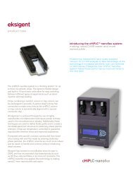
Introduction2The <strong>Eksigent</strong> ekspert <strong>nanoLC</strong> <strong>400</strong> systems are designed for HPLC applications that employdirect pumping at flowrates of several hundred nL/min up to µL/min.The ekspert <strong>nanoLC</strong> 415 and 425 systems include:• Binary gradient pumping system with loading pump. The flowrates depend on theinstalled flow modules.• <strong>Eksigent</strong> control software• ekspert <strong>nanoLC</strong> <strong>400</strong> autosampler• Autosampler solvent trayFigure 2-1ekspert <strong>nanoLC</strong> 425 system123Item Description1 Solvent tray2 Autosampler3 Pump<strong>Operator</strong> <strong>Guide</strong>ekspert <strong>nanoLC</strong> <strong>400</strong> <strong>Systems</strong>D5033460 C 15 of 174
IntroductionAccessory OptionsDepending on the system purchased, it may include the following accessory options:• cHiPLC ® system (PN 950-00070)• Column oven and mounting kit (PN 5019593)• External A/D converter (PN 5019951)ekspert <strong>nanoLC</strong> <strong>400</strong> <strong>Systems</strong><strong>Operator</strong> <strong>Guide</strong>16 of 174 D5033460 C
System Overview3This section provides an overview of the basic operations of the <strong>Eksigent</strong> ekspert <strong>nanoLC</strong> <strong>400</strong>system. It is written for standard <strong>nanoLC</strong> 415 and 425 systems. Some sections describe featureswhich may not be included in the <strong>nanoLC</strong> 415 system.For information on the cHiPLC ® system, refer to the cHiPLC ® System <strong>Operator</strong> <strong>Guide</strong>.Note: Prior to completing any procedures in this section, review the Regulatory andSafety Information.Turn On the SystemCaution: Potential System Damage: If any component of the system is unplugged fromthe AC mains, make sure that the power switch on the back of the component is in the “0”position prior to connecting the component to AC mains. Failure to do so could result incomponent damage.1. If required, connect the system to the AC mains using the provided power supply.Figure 3-1Back Panel—Pump I/O Switch in Off Position2. Turn on the <strong>nanoLC</strong> <strong>400</strong> pump using the I/O switch on the back panel.The green LED on the front of the system illuminates.3. Turn on the autosampler using the I/O switch on the back panel.<strong>Operator</strong> <strong>Guide</strong>ekspert <strong>nanoLC</strong> <strong>400</strong> <strong>Systems</strong>D5033460 C 17 of 174
System OverviewFigure 3-2Back Panel—Autosampler I/O Switch4. Turn on the computer and log in.5. Open the <strong>Eksigent</strong> control software.After the system completes initialization, the Acquisition window opens as shown inFigure 3-3. Refer to the <strong>Eksigent</strong> Control Software <strong>User</strong> <strong>Guide</strong> for detailedinformation on the features of the Acquisition window.ekspert <strong>nanoLC</strong> <strong>400</strong> <strong>Systems</strong><strong>Operator</strong> <strong>Guide</strong>18 of 174 D5033460 C
System OverviewFigure 3-3Acquisition WindowChannel Assignments in the <strong>Eksigent</strong> Control SoftwareThe ekspert <strong>nanoLC</strong> 415 and 425 systems have two or three pump channels, respectively. Thechannels are identified in this guide and in the software as Gradient 1, Gradient 2, and Loadingpump. Refer to Table 3-1 for channel assignments.In the software, select the channel in an active dialog or window by clicking the arrow beside thechannel. The channel typically shows in the top, right corner of a dialog or window.Table 3-1Channel Assignments with Nanoflow Modules in the Gradient ChannelsSystem Gradient 1 Gradient 2 Loading Pump415 Nanoflow (100 nL/min to1000 nL/min)425 Nanoflow (100 nL/min to1000 nL/min)N/ANanoflow (100 nL/min to1000 nL/min)Microflow (1 µL/min to50 µL/min)Microflow (1 µL/min to50 µL/min)Note: The flow rates in Table 3-1 are for the default flow modules. If different flowmodules are installed on the system, the flow rates will differ.Autosampler ConfigurationThe AB SCIEX FSE configures the autosampler during installation.Verify the Configuration Settings1. Open the Run Manager.<strong>Operator</strong> <strong>Guide</strong>ekspert <strong>nanoLC</strong> <strong>400</strong> <strong>Systems</strong>D5033460 C 19 of 174
System Overview2. Click Devices > Autosampler Device Settings.The Autosampler Configuration dialog opens.Figure 3-4 Autosampler Configuration Dialog—Configuration Tab10Hardware SettingsThe standard settings in the Hardware Settings group should be as shown in the table.Table 3-2Hardware SettingsFieldValueLoop Volume 10 µLNeedle + Tubing Volume 3.6 µLSyringe Volume 50 µLWash Speed2 µL/sFront Tray108 vialsThe wash speed used by the method is dependent on the wash speed settings.Loop volume must match the currently installed loop. If the sample loop size is changed, theLoop Volume configuration must be modified to reflect this change. New autosampler methodsmust also be created for this new sample loop size.ekspert <strong>nanoLC</strong> <strong>400</strong> <strong>Systems</strong><strong>Operator</strong> <strong>Guide</strong>20 of 174 D5033460 C
System OverviewTray CoolingThe sample temperature compartment provides a constant environment for all samples. Thetemperature range is 4°C to 40°C.To minimize temperature fluctuations, set the required temperature one hour before loading thesamples in the sample compartment. For biological samples, 6°C is advisable. If only a constanttemperature is required, set a temperature close to ambient. This saves on power consumptionand reduces condensation and the associated waste disposal issues.Figure 3-5Autosampler Configuration Dialog—Direct Control TabReplace the Mobile PhasesWARNING! Environmental Hazard: Always follow appropriate safety proceduresand local requirements when handling or disposing of waste chemicals. Refer tothe Material Safety Data Sheets for the mobile phases.AB SCIEX recommends replacing solvents each month. After replacing the solvent, purge andflush the system.Tip! Sonicate or sparge the mobiles phases with helium to degas before adding themto the bottles.Table 3-3 describes typical mobile phase mixtures for ekspert <strong>nanoLC</strong> 415 and 425 systems. The<strong>nanoLC</strong> 415 system does not have a Gradient 2 channel.<strong>Operator</strong> <strong>Guide</strong>ekspert <strong>nanoLC</strong> <strong>400</strong> <strong>Systems</strong>D5033460 C 21 of 174
System OverviewCaution: Potential System Damage: Use LC/MS-grade pre-made solvents such as thosefrom Burdick-Jackson. These solvents can be ordered from VWR:- PN BJLC452-2.5 - 0.1% Formic Acid Water (HPLC-grade water with 0.1% formic acid)- PN BJLC441-2.5 - 0.1% Formic Acid Acetonitrile (acetonitrile with 0.1% formic acid)Table 3-3Typical Mobile Phase MixturesBinary Mixture A Binary Mixture B ModifierGradient 1100% water 100% acetonitrile 0.1% formic acidGradient 2100% water 100% acetonitrile 0.1% formic acidLoading Pump100% water N/A 0.1% formic acidAs shown in Figure 3-6, the mobile phase outlets are located on the right side of the back of thepump. The gradient pump outlet (or outlets) is located at the top.Figure 3-6 Back Panel Pump—Mobile Phase Outlets (5)Required Materials• HPLC-grade mobile phase A• HPLC-grade mobile phase B• Waste container that can contain at least 100 mL of solvent1. Discard old solvents that are in the mobile phase bottles.2. Clean the bottles with appropriate solvents.3. Fill bottle A with mobile phase A and bottle B with mobile phase B. Refer to Table 3-3.4. Place the tubing and filters in the bottles and secure the lids on the bottles.5. Place the refilled bottles on top of the autosampler in the solvent tray.ekspert <strong>nanoLC</strong> <strong>400</strong> <strong>Systems</strong><strong>Operator</strong> <strong>Guide</strong>22 of 174 D5033460 C
System OverviewCaution: Potential System Damage: If the pump is dry, manually prime thepump. Refer to Prime the Pump.6. For a wet pump, proceed to purge and flush the system. Refer to Purge the Pumpand Flush the Pump.Specify the Maximum FlowrateThe Maximum Flowrate is automatically set when a flow module is inserted. For most nanoflowapplications, 1000 nL/min is appropriate, as shown in Figure 3-7.Figure 3-7Hardware Options Tab—Maximum Flowrate1. Click System > Instrument Configuration.2. On the Hardware Options tab, click the correct channel.3. Select the Allow Customization check box.4. Type a Maximum Flowrate in the field.5. Click OK.Prime the PumpPriming is required for dry pumps. It should not be required under normal operating conditions.This priming procedure may also be used to rapidly exchange solvents.Priming the pump requires manual intervention. This procedure involves manually drawingsolvent through the fluidic path with a 5 mL syringe. While the priming syringe minimizesleachables and extractables with commonly used HPLC solvent systems, the solvent drawn into<strong>Operator</strong> <strong>Guide</strong>ekspert <strong>nanoLC</strong> <strong>400</strong> <strong>Systems</strong>D5033460 C 23 of 174
System Overviewand forced out of the syringe during priming will enter the pump flow path. Contamination mayoccur during these steps.Caution: Potential System Contamination: Failure to keep the priming syringe andconnecting tubing free of contamination will lead to potential plugging and contaminationof the ekspert <strong>nanoLC</strong> system. Follow good LC/MS laboratory practices.WARNING! Personal Injury Hazard: Use safety glasses at all times. Use of thepriming syringe will result in compressed gas and liquids. Be prepared forunexpected spray (for example, the syringe or fittings may slip and liquid mayspray).Required Materials (supplied)• 5 mL GasTight priming syringe• Prime valve connector tubing and fittings• Waste container (minimum 100 mL) (not supplied)Prime a Dry Pump1. Identify the bottles, solvent lines, and solvents to be changed.2. Attach the priming syringe to the front of the pump for the solvent being changed.The syringe should be empty prior to connection to the system. Connect the syringewith the attached connector tubing and adapters. The threaded end of theconnection tubing plumbs into the pump and the luer lock fitting connects to thesyringe. Refer to Figure 3-8.Figure 3-8Front Panel Pump—Manual Prime Ports3. Open the purge valves.a. In the Acquisition window, click System > Mobile Phases.b. Click More.c. Click Prime.ekspert <strong>nanoLC</strong> <strong>400</strong> <strong>Systems</strong><strong>Operator</strong> <strong>Guide</strong>24 of 174 D5033460 C
System Overview4. Follow the instructions in the window to prime the pump.a. Stop all flow.b. On the front panel, turn the manual prime valve to Fill for the appropriatechannel.c. Fill the syringe with solvent by pulling the syringe until the syringe is full.This step pulls solvent from the bottle, through the line into the back of theinstrument, through the internal tubing and, finally, into the syringe body. Ittakes about 5 mL with a dry line for liquid to reach the syringe from the solventreservoir.d. Turn the manual prime valve to Prime.e. Slowly but firmly push the liquid into the pump.When approximately 2.5 mL of liquid has been pushed into the pump, liquidshould begin entering the waste container through the waste/purge externallines. This is an indication of proper priming.f. When liquid is entering the waste container, turn the manual prime valve toRun.g. The syringe may have some residual pressure in it. Unload or depressurizethe syringe by pulling back on the plunger. This prevents spilling or sprayingsolvent from the syringe body when disconnecting it from the system.h. Once the internal pressure of the syringe has been relieved, remove thesyringe from the pump by unscrewing the adapter tubing piece from thebulkhead on the front of the pump.5. Repeat these steps for each pump line to be primed.Exchange the SolventTip! Hold the syringe vertically with the plunger above the syringe tip tomake sure that any air that is in the syringe is not forced back into the pumpwhen the plunger is depressed in subsequent steps.If the pump is wet, miscible solvents may be changed. To introduce a solvent, identify andintroduce mutually miscible intermediate solvents prior to introducing the final solvents.Caution: Potential System Damage: Do not follow one solvent with an immisciblesolvent. Doing so may lead to a variety of undesirable results and unpredictable behaviorand potential instrument damage.If the pump is wet, introduce an air gap in the lines holding the existing liquid. This gap can stopthe new solvent from being contaminated with existing solvent in the line.1. In the <strong>Eksigent</strong> control software, stop all flows.Tip! Attaching the syringe at the beginning of this procedure helpsprevent leaks from the priming port when the prime valve is switched.2. Introduce an air gap.a. Identify the bottle and line to be changed.<strong>Operator</strong> <strong>Guide</strong>ekspert <strong>nanoLC</strong> <strong>400</strong> <strong>Systems</strong>D5033460 C 25 of 174
System Overviewb. Place a new labelled bottle filled with solvent near the solvent bottle to bechanged out.c. In the <strong>Eksigent</strong> control software, click System > Mobile Phases > MORE andspecify the channel (that is, Gradient 1, Gradient 2, or Loading pump).d. In the Purge Settings group, select the solvent (A or B) to be changed.e. In the mobile phase bottle, pull the inlet frit out of the liquid so that the filter canbe cleared of old solvent.f. Specify 5 purge cycles, and click Purge Now.g. As the pump draws liquid up the line, an air gap forming in the line at one endof the reservoir.h. Remove the old bottle when the end of the line is clear of solvent.i. Replace the old bottle with a new bottle and place the mobile phase filters intothe new liquid.3. Proceed to step 2 in the section, Prime a Dry Pump.Purge the PumpPurging rapidly replaces the solvent in the pump. Repeat this procedure for all channels, ifnecessary.Prerequisite Procedure• Replace the Mobile Phases1. In the Acquisition window, click System > Mobile Phases.2. Verify that the software settings for solvent composition match the actual solvents inthe bottles.• Binary mixture A sets the composition for Solvent A (mobile phase).• Binary mixture B sets the composition for Solvent B (mobile phase).3. If necessary, repeat step 2 for Gradient 2 and Loading pump.4. Click More to open the Purge Settings and Flush Settings.ekspert <strong>nanoLC</strong> <strong>400</strong> <strong>Systems</strong><strong>Operator</strong> <strong>Guide</strong>26 of 174 D5033460 C
System OverviewFigure 3-9Mobile Phases Dialog—Purge and Flush Settingsa. In the Purge Settings group, select the Side A or Side B check box for thepump to purge.b. Set the number of purge cycles to 20.c. Click Purge Now.The pump begins to execute purge cycles. While the pump is purging, verifythat the mobile phases are pulled through the mobile phase tubing to thepump.d. Locate the waste tubing of the pump being purged. After about 8 purges, themobile phase should be purged through the waste tubing.Flush the PumpFlushing replaces the solvent in the capillaries connecting the pump to the pump outlet throughthe flow modules. Repeat this procedure for all channels, if necessary.Prerequisite Procedure• Purge the Pump1. Disconnect the tubing from the pump outlet.2. Connect a waste line to the pump outlet.3. In the Acquisition window, select the appropriate channel in the top right corner ofthe window.4. Click System > Mobile Phases.5. Click More.6. In the Flush Settings group, type 50 (µL) for the Total Volume.<strong>Operator</strong> <strong>Guide</strong>ekspert <strong>nanoLC</strong> <strong>400</strong> <strong>Systems</strong>D5033460 C 27 of 174
System Overview7. Specify an appropriate Flush Flowrate for the maximum flow of the channel.• For high-flow channels, type 10 (µL/min) for the Total Flowrate.• For low-flow channels, type 1000 (nL/min) for the Total Flowrate.Caution: Potential System Damage: Be sure to disconnect all traps, columnsand filters before proceeding. Flushing the system with a column connectedcould damage the column or create leaks in external connections.8. Click Flush Now.9. After the flush sequence ends, click OK to close the Mobile Phases dialog.Replace the Flow Module CartridgesThe flow module cartridges are interchangeable and may be replaced as needed to change thepump flowrate range.Caution: Potential System Damage: Handle the flow modules with care. Flow modulesrequire careful use and storage. Use of a tool other than the supplied break-over torquewrench on the flow modules may result in damage to the unit and system. If the tool ismisplaced, order a new one from <strong>Eksigent</strong>. Damage to the flow module from misuse,including failure to use only the supplied torque wrench, may void the instrumentwarranty. Store flow modules in a dust-free environment to avoid plugging.Caution: Potential System Damage: Never leave solvents with non-volatile salts in theflow module when removing the cartridge. Doing so will damage the flow module.Tip! Each module has an A and B side. The A side is typically filled with an aqueoussolution. To prevent microbial growth, prior to removing and storing the module, flushthe module with an organic solution such as isopropanol. Refer to Prime the Pump onpage 23 for information on how to quickly exchange a solvent in the pump.Required Materials• Small break-over torque wrench (PN 5019560)Caution: Potential System Damage: Only use the break-over wrench supplied with thesystem. Over-torquing is easily possible and will damage parts and void the warranty.• One of the following flow modules:• Nano gradient flow module, 0.1 µL/min to 1 µL/min (PN 5018236)• Low micro gradient flow module, 1 µL/min to 10 µL/min (PN 5018237)• High micro gradient flow module, 5 µL/min to 50 µL/min (PN 5018238)• Loading pump isocratic flow module, 1 µL/min to 50 µL/min (PN 5018239)1. Make sure that the current pumping solvent is miscible with the contents of the flowmodule.2. Replace solvents if necessary.3. Turn off the system.4. Remove the flow module cartridge.ekspert <strong>nanoLC</strong> <strong>400</strong> <strong>Systems</strong><strong>Operator</strong> <strong>Guide</strong>28 of 174 D5033460 C
System Overview5. Pull down the slide on the flow module cartridge to protect the fluidic connectorsduring storage.6. Push up the slide on the new flow module cartridge.7. Insert the new flow module cartridge in the system. It can only go in one way.8. Using the calibrated torque wrench, secure the cartridge.Hold the wrench only by the break-over handle to obtain the calibrated results.9. Flush the module with a minimum of 50 µL of the current solvent.When you change the modules, the pump may seem to have zero pressure on Pc.Because Pc is used to calculate flow, the channel may initially not seem to pump. Itis actually pumping out the air introduced during the module change. Once the air isgone, Pc will come up, the liquid begins flowing through the channel, and thesoftware shows normal pressures.Set the Column Oven TemperatureThe column oven is an optional component. It is associated with a single Channel. On the backpanel, the column oven connects to Channel 1.1. Click System > Direct Control.2. In the Direct Control dialog, select Gradient 1.3. Type the column Setpoint temperature (for example, 40°C).Figure 3-10 Direct Control Dialog—Setpoint Temperature4. In the Column Oven/Heater group, click Start.<strong>Operator</strong> <strong>Guide</strong>ekspert <strong>nanoLC</strong> <strong>400</strong> <strong>Systems</strong>D5033460 C 29 of 174
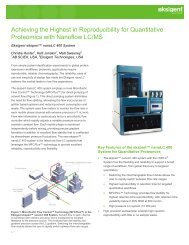
System OverviewThe column begins to heat. The current temperature is visible in the upper, rightcorner of the Acquisition window for Gradient 1 when the oven is installed and runon.Figure 3-11 Acquisition Window—Column Oven TemperatureRefer to the <strong>Eksigent</strong> Control Software <strong>User</strong> <strong>Guide</strong> for information on using thecolumn oven to explore the impact of varying column temperature in the RunManager window. The Run Manager window allows a queue to be set up anddifferent column temperatures to be entered for each run.Caution: Potential System Damage: Do not leave the column oven coveropen for long periods of time while the column oven is operating. The heaterunit is designed to operate as a closed system. Leaving the cover open withthe heater on at high temperatures may damage the heater system.Configure the A/D ConverterAn optional A/D converter is required for connection to external detectors such as UV orfluorescence detectors. The FSE installs the optional A/D converter during installation of theekspert <strong>nanoLC</strong> <strong>400</strong> system.The section assumes the ekspert <strong>nanoLC</strong> <strong>400</strong> system is connected to a computer and that the<strong>Eksigent</strong> control software has been installed. By default, all the software is installed for the A/Ddevice when the <strong>Eksigent</strong> software package is installed on the control computer.ekspert <strong>nanoLC</strong> <strong>400</strong> <strong>Systems</strong><strong>Operator</strong> <strong>Guide</strong>30 of 174 D5033460 C
System OverviewFigure 3-12 A/D ConverterItem Description1 Screw terminal pins (21-40)2 LED*3 Screw terminal pins (1-20)4 USB connector* If the LED is on with a steady green, then the device is connected to a computer or externalUSB hub. If the LED blinks once, then a USB command has been received by the device.Continuously blinking indicates an analog input scan is taking place.Set the Scale and A/D Input Voltage RangeSelection1. Open the <strong>Eksigent</strong> control software.2. Select System > Hardware Diagnostics.3. On the External A/D tab, select the A/D Input Voltage Range Selection from thelist.<strong>Operator</strong> <strong>Guide</strong>ekspert <strong>nanoLC</strong> <strong>400</strong> <strong>Systems</strong>D5033460 C 31 of 174
System OverviewFigure 3-13 Hardware Diagnostics Window—External A/D Tab4. (Optional) In the Scale field, specify a scaling factor.Many devices output either -1 V to +1 V or -10 V to +10 V. Select a scaling factorbased on the output range settings in the detector. If the data appears noisy oncerunning, then the Input Voltage Range Selection is not taking advantage of the fulldynamic range of the device's A/D conversion. Use the live view of the inputs to theA/D device to adjust and optimize these values for the ideal signal-to-noise.5. Click Close.Set the Data Acquisition Rate for Including the A/D ConverterDetector Stream in an LC MethodWhen the A/D converter is enabled, the Detector tab shows in the LC Method Settings dialog.ekspert <strong>nanoLC</strong> <strong>400</strong> <strong>Systems</strong><strong>Operator</strong> <strong>Guide</strong>32 of 174 D5033460 C
System Overview• On the Detector tab, specify an Acquisition Rate.Figure 3-14 LC Method Settings Dialog—Detector TabTip! 10 Hz is a good starting place for many chromatographic systems. Itis possible to go higher for fast chromatography with very narrow peakshapes. A 10 Hz rate means that a 3 second wide peak is sampled 30times.Configure the Appearance Settings in the <strong>Eksigent</strong> ControlSoftware1. Open the <strong>Eksigent</strong> control software.2. Click System > Appearance Settings.3. Click the number of boxes in the External A/D converter group that are wired withinputs from the detector.<strong>Operator</strong> <strong>Guide</strong>ekspert <strong>nanoLC</strong> <strong>400</strong> <strong>Systems</strong>D5033460 C 33 of 174
System OverviewFigure 3-15 Appearance Settings Dialog—External A/D Channel Check Box4. Make sure that the Internal A/D channel check box is clear. The ekspert <strong>nanoLC</strong><strong>400</strong> system does not have an internal A/D channel.Once configured, the A/D data stream should be visible on the screen. Refer to the<strong>Eksigent</strong> Control Software <strong>User</strong> <strong>Guide</strong> for more information.ekspert <strong>nanoLC</strong> <strong>400</strong> <strong>Systems</strong><strong>Operator</strong> <strong>Guide</strong>34 of 174 D5033460 C
System OverviewEquilibrate the SystemPrerequisite Procedure• Replace the Mobile PhasesUse the Direct Control dialog to equilibrate the system following system power-up, a change ofsolvent, or a change of column. Open the Autosampler Configuration window to toggle theinjection valve between load and inject positions. Toggling flushes the sample loop andinterconnecting ports.1. In the Acquisition window, select the appropriate channel in the top right corner ofthe window.2. Click System > Direct Control.Figure 3-16 Direct Control Dialog3. Make sure that Conserved Flow is selected and set A (%) and B (%) to 90 and 10,respectively.This is the mobile phase composition used for equilibration.Use Conserved Flow to choose a total flowrate and percent composition. UseIndependent Flow to select independent flowrates for A and B. Conserved Flow ismost commonly used with the ekspert <strong>nanoLC</strong> <strong>400</strong> systems.4. Set the Total flowrate to <strong>400</strong> (nL/min) or other appropriate flowrate.5. Click Start to start the pump flowing and begin equilibration.6. In the Acquisition window, click Devices > Autosampler Device Settings.7. Flush the autosampler switching valve:a. Click the Direct Control tab.b. In the Injection Valve group, flush the switching valve by alternately clickingLoad Position and Inject Position to release trapped air.<strong>Operator</strong> <strong>Guide</strong>ekspert <strong>nanoLC</strong> <strong>400</strong> <strong>Systems</strong>D5033460 C 35 of 174
System OverviewThe sample loop is inline when the valve is in the Inject Position and out of theLC flow path in Load Position. The solvent that is in the loop when the valve isswitched out of line remains there.Figure 3-17 Autosampler Configuration Dialog—Direct Control Tab8. Allow the system to equilibrate for approximately 10 minutes or until it is well flushedand pressure on Pc has stabilized.Verify the FlowrateBefore operating the system, verify that the flowrate is properly calibrated. This is done bymeasuring the time it takes to move a liquid front through a graduated capillary of known volume.Required Materials• Flow calibration assembly (PN 801-00063) for high-flow rate channel (includes 20 µLpipettes)• Flow calibration assembly (PN 801-00064) for low-flow rate channel (includes 5 µL graduatedpipettes)• Timer1. Re-initialize the Pressure Transducers.2. Attach the appropriate flow calibration assembly to the appropriate mobile phaseoutlet.3. In the <strong>Eksigent</strong> control software, click System > Direct Control.ekspert <strong>nanoLC</strong> <strong>400</strong> <strong>Systems</strong><strong>Operator</strong> <strong>Guide</strong>36 of 174 D5033460 C
System OverviewFigure 3-18 Direct Control Dialog—Flowrate Check4. In the top right corner of the dialog, select the appropriate channel.5. In the Direct Control dialog, for a Gradient pump, set channel A to 95% and anappropriate Total flowrate for that channel.• 5 µL/min for a high-flow channel• 500 nL/min for a low-flow channelFor the loading pump, set channel A to 100%.6. Click Start.7. When the liquid front reaches the black mark on the pipette, begin timing.• With the high flow calibration assembly, the time it takes for the liquidmeniscus to travel from the black stripe to the end of the capillary should be240 seconds.• With the low flow calibration assembly, the time it takes for the liquid meniscusto transit across two segments of the capillary (2 µL) should be 240 seconds.8. Click Stop in the Direct Control dialog when the liquid front reaches the end of thepipette or the appropriate black mark on the pipette.9. Inspect the flowrate to confirm that the system is working within an acceptablerange.<strong>Operator</strong> <strong>Guide</strong>ekspert <strong>nanoLC</strong> <strong>400</strong> <strong>Systems</strong>D5033460 C 37 of 174
System OverviewTable 3-4FlowrateDifference from Time (sec)ActionExpected Time± < 5% 228 to 252 Do nothing.± 5 to 20% 192 to 228, or252 to 288Recalibrate theflowmeters. Refer toCalibrate theFlowmeters onpage 67.± > 20% < 192, or > 288 Refer to Table 6-3 onpage 96 in BestPractices andTroubleshooting.Contact an AB SCIEXFSE if the discrepancypersists.10. Disconnect the calibration assembly and blow out the liquid inside the pipette using apipette bulb or can of compressed air.11. Set channel B to 95% and repeat steps 5 through 10 to verify the flowrate for pumpB.12. Disconnect the calibration assembly.13. Repeat this procedure as necessary for other channels.Prepare to Run a SequenceUse the Run Manager to queue samples to be run in sequence. The sequence typically containsone or more LC methods and autosampler method. Autosampler methods and LC methods arecreated and saved so that they are available to be selected and run in the Run ManagerSequence.Tip! Make sure that the ekspert <strong>nanoLC</strong> <strong>400</strong> autosampler is selected in the Devices >AutoSampler Type menu within the Run Manager before continuing to build anautosampler method.Confirm the Autosampler ConfigurationDuring installation, the FSE configures the autosampler in the <strong>Eksigent</strong> control software. Confirmthat the ekspert <strong>nanoLC</strong> <strong>400</strong> autosampler configuration has not changed. Refer to Figure 3-19for typical values for the Hardware Settings.ekspert <strong>nanoLC</strong> <strong>400</strong> <strong>Systems</strong><strong>Operator</strong> <strong>Guide</strong>38 of 174 D5033460 C
System OverviewFigure 3-19 Autosampler Configuration Dialog—Configuration TabParameterTypical ValueLoop Volume10 µL (dependent on the installed hardware)Needle and Tubing Volume 3.6 µLSyringe Volume50 µL (standard installed syringe volume)Wash Speed2 µL/minNote: With the exception of Wash Speed, the values in Figure 3-19 are dependent onthe hardware installed.Create Autosampler and LC Methods—DirectInjectionComplete the following procedures:1. Create the Autosampler Method.2. Create the LC Method—Gradient.<strong>Operator</strong> <strong>Guide</strong>ekspert <strong>nanoLC</strong> <strong>400</strong> <strong>Systems</strong>D5033460 C 39 of 174
System OverviewCreate the Autosampler MethodThe parameters used for loading the sample into the injection valve loop and for rinsing thesyringe and sample needle are stored in the autosampler method. This procedure creates anautosampler method appropriate for loading the sample loop using direct on-column injectionand running a gradient with Gradient 1.1. Place the sample vial containing the sample or standard test mixture in vial positionC01 of the autosampler 108-vial tray.2. In the Acquisition window, click Run Manager.Tip! If the current tray does not display a picture of the 108-vial tray in theRun Manager window, then click Devices > Autosampler DeviceSettings and select the tray type. Open the Run Manager window afterchanging the tray type.Figure 3-20 Run Manager Window3. Make sure that the Run Manager window shows the columns in Figure 3-20.• If they do not show, then click Edit > Choose Columns and select theappropriate column headings. Click OK.4. In the Run Manager window, click Autosampler Methods.ekspert <strong>nanoLC</strong> <strong>400</strong> <strong>Systems</strong><strong>Operator</strong> <strong>Guide</strong>40 of 174 D5033460 C
System OverviewFigure 3-21 Method Editor Dialog5. Click File > Save as and save the method with a new name.6. Edit the method as required.Injection Type: Direct InjectionGradient Pump Channel: Gradient Pump 1Sample Pickup: µL Pick UpSample pick up volume: 1 µLNeedle height: 2 mm7. Save the method.Tip! Autosampler methods created with the Method Editor dialog aretypically Gradient Channel specific. Use a name that clearly states thechannel and other information related to the method. The example methodfile name (Figure 3-20) includes the information required to identify themethod.8. Click OK to close the Method Editor dialog.<strong>Operator</strong> <strong>Guide</strong>ekspert <strong>nanoLC</strong> <strong>400</strong> <strong>Systems</strong>D5033460 C 41 of 174
System OverviewNote: Refer to Create an Advanced Method on page 122 for a detaileddescription of how to create an advanced method.Create the LC Method—GradientThe conditions used to separate the sample are specified in the LC method.1. In the Run Manager window in the LC channel column, select an appropriatechannel.2. Click LC Methods.3. In the Name field, type a method name and click Save.4. (Optional) Specify HPLC column information appropriate for the experiment. Thisinformation is stored with the LC method file.5. On the Run Conditions tab, in the Pre-Run group, select the Flush column checkbox.6. Specify a time appropriate to equilibrate the pump, connected tubing and columnusing 100% initial flowrate conditions.This is the pre-run equilibration time and the duration is often experimentallydetermined. Five minutes is a typical setup starting point.Figure 3-22 LC Method Settings Dialog—Run Conditions Tabekspert <strong>nanoLC</strong> <strong>400</strong> <strong>Systems</strong><strong>Operator</strong> <strong>Guide</strong>42 of 174 D5033460 C
System Overview7. In the Sample Injection group, click Metered.This option signals the injection valve to be placed in the inject position for theduration of the Metered Injection (that is, 10000 nL). Refer to Standard and MeteredInjection Parameters on page 44.8. Make sure that the check box in the Post-Run group is cleared.9. On the Gradient Table tab, specify the gradient parameters as shown in Figure 3-23.• Add new steps to the table by clicking the arrows (>>) to the left of the table.• Delete steps by clicking the X.• Set the Total flowrate on the right side of the dialog.• If events such as Lamp on/off, Valve state toggles, or Output switching arerequired, specify them in the Events column.Figure 3-23 LC Method Settings Dialog—Gradient Table Tab10. On the Gradient Profile tab, review the gradient to make sure it is correct.11. When the method is complete, click Save.12. Click OK to close the editor.<strong>Operator</strong> <strong>Guide</strong>ekspert <strong>nanoLC</strong> <strong>400</strong> <strong>Systems</strong>D5033460 C 43 of 174
System OverviewFigure 3-24 LC Method Settings Dialog—Gradient Profile TabNote: Set the mobile phase composition by clicking and dragging points on the graphor by setting the % of A or B in the Profile Editor groupStandard and Metered Injection ParametersStandard: Signals the autosampler to place the valve in the Inject position at the start of the runand to switch back to Load at the end of the run.Metered: Switches the valve to Inject for a defined volume prior to the start of a run, then to Loadduring the run.Example: Metered injection of 15 000 nL with a flowrate of 3 µL/min (specified inthe Gradient Table tab)At the start of the Metered injection, the 6-port valve on the autosampler switches from Load toInject. The remains in Inject until 15 µL (15 000 nL) has flowed through the loop, and then back toLoad. At the specified flowrate of 3 µL/min, this Metered injection should take approximately 5minutes to complete.ekspert <strong>nanoLC</strong> <strong>400</strong> <strong>Systems</strong><strong>Operator</strong> <strong>Guide</strong>44 of 174 D5033460 C
System OverviewCreate Autosampler and LC Methods—Trap-and-EluteComplete the following procedures:1. Create the Autosampler Method.2. Create the LC Method—Loading Pump.3. Create the LC Method—Gradient.Create the Autosampler MethodThe parameters used for loading the sample into the injection valve and for rinsing theautosampler syringe and sample needle are stored in the autosampler method. This sectioncreates an autosampler method appropriate for loading a trap column using the loading pump,and running a gradient with Gradient 1.1. Place the sample vial containing the standard test mixture in vial position C01 ofautosampler 108-vial tray.2. In the Acquisition window, click Run Manager.Figure 3-25 Run Manager WindowTip! If the current tray does not display a picture of the 108-vial tray in theRun Manager window, click Devices > Autosampler Device Settings andselect the tray type. Open the Run Manager window after changing the traytype.3. Make sure the columns in Figure 3-25 appear in the Run Manager window.<strong>Operator</strong> <strong>Guide</strong>ekspert <strong>nanoLC</strong> <strong>400</strong> <strong>Systems</strong>D5033460 C 45 of 174
System OverviewIf necessary, click Edit > Choose Column and select the appropriate columns fordisplay.4. In the Run Manager window, click Autosampler Methods.Figure 3-26 Method Editor Dialog5. Click File > Save as and save the method with a new name.6. Edit the method as required.Injection Type: Trap EluteGradient Pump Channel: Gradient Pump 1Optional Valves: ISS-A ValveSample Pickup: µL Pick UpSample pick up volume: 1 µLNeedle height: 2 mmNote: Refer to Method Editor Options on page 120 for a detaileddescription of the features in the autosampler Method Editor dialog.ekspert <strong>nanoLC</strong> <strong>400</strong> <strong>Systems</strong><strong>Operator</strong> <strong>Guide</strong>46 of 174 D5033460 C
System Overview7. Save the method.8. Click OK to close the Method Editor dialog.Note: Refer to Create an Advanced Method on page 122 for a detaileddescription of how to create an advanced method.Create the LC Method—Loading Pump1. In the LC Channel column, select Loading pump.2. In the Run Manager window, click LC Methods.Figure 3-27 LC Method Settings Dialog—Summary Tab3. In the Name field, type a method name and click Save.4. (Optional) Specify column information appropriate to the experiment.This information is stored with the LC method file.5. On the Run Conditions tab, in the Pre-Run group, select the Flush column checkbox and specify a time of 0.1 minutes using 100% initial flowrate conditions.<strong>Operator</strong> <strong>Guide</strong>ekspert <strong>nanoLC</strong> <strong>400</strong> <strong>Systems</strong>D5033460 C 47 of 174
System OverviewFigure 3-28 LC Method Settings Dialog—Run Conditions Tab6. In the Sample Injection group, click None.Refer to Create the LC Method—Gradient on page 50.7. In the Post-Run group, make sure that the check box is cleared.8. On the Gradient Table tab, specify the loading pump parameters.• Type the appropriate Qa (flowrate) and Time.In this method, Time is the amount of time that the Loading pump is flowingthrough the sample loop, pushing liquid over to the trap column. Make surethat this time is long enough to properly load the sample onto the trap andwash away any salts or detergents.ekspert <strong>nanoLC</strong> <strong>400</strong> <strong>Systems</strong><strong>Operator</strong> <strong>Guide</strong>48 of 174 D5033460 C
System OverviewFigure 3-29 LC Method Settings Dialog—Gradient Table Tab9. On the Gradient Profile tab, review the gradient to make sure it is correct.<strong>Operator</strong> <strong>Guide</strong>ekspert <strong>nanoLC</strong> <strong>400</strong> <strong>Systems</strong>D5033460 C 49 of 174
System OverviewFigure 3-30 LC Method Settings Dialog—Gradient Profile Tab10. When the method is complete, click Save.Create the LC Method—GradientThe conditions used for separating the sample are specified in the LC method.1. In the Run Manager window, select an appropriate channel in the LC channelcolumn.2. Click LC Methods.3. In the Name field, type a method name and click Save.4. (Optional) Specify column information appropriate for the experiment.This information is stored with the LC method file.ekspert <strong>nanoLC</strong> <strong>400</strong> <strong>Systems</strong><strong>Operator</strong> <strong>Guide</strong>50 of 174 D5033460 C
System Overview5. On the Run Conditions tab, in the Pre-Run group, select the Flush column checkbox and specify a time appropriate to equilibrate the pump, connected tubing, andcolumn, using 100% initial flowrate conditions.Figure 3-31 LC Method Settings Dialog—Run Conditions Tab6. In the Sample Injection group, click Standard. Refer to Standard and MeteredInjection Parameters on page 44.7. Make sure that the check box in Post-Run group is cleared.8. On the Gradient Table tab, specify the gradient parameters as shown in Figure 3-32.• Add new steps by clicking the >> to the left of the table.• Delete steps by clicking the X.• Set the Total flowrate on the right side of the dialog.<strong>Operator</strong> <strong>Guide</strong>ekspert <strong>nanoLC</strong> <strong>400</strong> <strong>Systems</strong>D5033460 C 51 of 174
System OverviewFigure 3-32 LC Method Settings Dialog—Gradient Table Tab9. On the Gradient Profile tab, review the gradient to make sure it is correct.Figure 3-33 LC Method Settings Dialog—Gradient Profile Tabekspert <strong>nanoLC</strong> <strong>400</strong> <strong>Systems</strong><strong>Operator</strong> <strong>Guide</strong>52 of 174 D5033460 C
System OverviewNote: The mobile phase composition can be set by clicking and draggingpoints on the graph or by setting the % of A or B in the Profile Editor group.10. When the method is complete, click Save.11. Click OK to close the editor.Create the Run TableThe Run Table ties together an autosampler and one or more LC methods with a sample vial andtray position. Use the Run Table to specify descriptive information related to the sample oranalysis. This section creates a Run Table to run two samples with a trap-and-elute method.1. In the Run Manager window, click Edit > Erase Table.Figure 3-34 New Run Table2. Click File > Save As and type Trap Loading in the File name field.3. Click Save.4. In the first line in the run table, double-click the Autosampler Method field andselect the autosampler method created above.5. In the Tray column, type 1 and in the Vial column, type C01.Alternatively, specify the vial location by clicking the vial position on the picture of thesample tray in the Run Manager window (bottom, left corner).6. In the Channel column, specify Loading Pump.7. Double-click the LC Method field and select the loading pump method createdabove.<strong>Operator</strong> <strong>Guide</strong>ekspert <strong>nanoLC</strong> <strong>400</strong> <strong>Systems</strong>D5033460 C 53 of 174
System Overview8. In the next line of the Run Manager table, leave the autosampler method, tray, andvial location empty.9. In the Channel column, specify Gradient 1.10. Double-click the LC Method field and select the gradient method created above.11. For each sample to be run, create the two lines in the table, as shown in Figure 3-35.Figure 3-35 Run Manager Window—Two Samples12. Select the Run check box to specify the lines to run.13. In the Run Sequence group, select Sequential mode.14. (Optional) Select the Flush/Equilibrate when Idle check box to start flow of thepump at the conditions specified in the Pre-Run flush section of each LC method.To edit the first two lines, clear the Flush/Equilibrate when Idle check box.15. Click File > Save to save the Run Table.Start the RunSelect the samples to be analyzed by placing a check mark in the box to the right of theappropriate row numbers in the Run Table.Selecting the Flush/Equilibrate when Idle check box initiates the pre-run flush for the firstmethod. With this option selected, the system continues to flush after the sequence as defined bythe pre-run flow conditions in the LC method for each channel.Initiate the run by clicking Start. The Start button then shows as a red Stop that can be used toabort the run at any point during the analysis.ekspert <strong>nanoLC</strong> <strong>400</strong> <strong>Systems</strong><strong>Operator</strong> <strong>Guide</strong>54 of 174 D5033460 C
System OverviewAfter the flowrate stabilizes, the sample injection process begins. For the Trap loading run tablecreated earlier in this section, the Loading pump method runs first. The Gradient pump will flow ifthe Flush/Equilibrate when idle check box is selected, but the method will not run yet.While the run is in progress, the Acquisition window shows the specified flow profiles forsolvents A and B, as well as their actual flowrates (Q). To add or delete traces from the display,click System > Appearance Settings in the Acquisition window and select the desired items.Refer to Figure 3-37 on page 57.Figure 3-36 Acquisition Window—Real-time View of Pressure and Flow DataTo zoom in on a particular area of the chromatogram, click the display and drag a box around thearea of interest to enlarge that area. To zoom back out, right-click and select Zoom Out or Back.Status information such as %A, %B and Time Remaining is shown at the bottom of the screenduring the run. Status bars at the top of the window show the actual flowrate for pump A (Qa) andpump B (Qb) and several pressures.View the Run Status in the Run Manager WindowDuring a run, the color of the row in the run table indicates the status:• White–the run can be started• Light green–equilibrating• Dark green–running• Red–stopped• Yellow–an error occurred• Gray–completed<strong>Operator</strong> <strong>Guide</strong>ekspert <strong>nanoLC</strong> <strong>400</strong> <strong>Systems</strong>D5033460 C 55 of 174
System OverviewStop a Run in the Run Manager Window1. Click Stop to stop the run.2. To start again, either:• Click Start to start the run again, beginning at the next row in the run table.orControl Buttons• Click (Reset) to clear the status of every row in the run table, and thenclick Start to start the run again at the first row in the run table.Table 3-5 shows the buttons available in the Acquisition window.Table 3-5 Control Buttons in the Acquisition WindowClick...To...Pause the run.The system is maintained with its current conditions indefinitely until the run isstopped or resumed.To resume the run, click (Resume).To stop the run, click (Stop).Change the run duration.Select the number of minutes to extend or shorten the run.Stop the run.The run stops and the pump resets.View a dialog containing information about the sample run and other acquisitioninformation saved with the data file.(Not available during a run) Open the Direct Control dialog.Use this dialog to change the mobile phase composition, flowrate, valve position,and column oven temperature when the system is not performing a run.ekspert <strong>nanoLC</strong> <strong>400</strong> <strong>Systems</strong><strong>Operator</strong> <strong>Guide</strong>56 of 174 D5033460 C
System OverviewAdd or Remove Traces in the Acquisition Window1. In the Acquisition window, click System > Appearance Settings to open theAppearance Settings dialog (Figure 3-37).Figure 3-37 Appearance Settings Dialog2. Select the items to view in the plot and, optionally, set the colors for the traces byclicking on the color box.3. Click Apply and then OK to save the changes and close the dialog.<strong>Operator</strong> <strong>Guide</strong>ekspert <strong>nanoLC</strong> <strong>400</strong> <strong>Systems</strong>D5033460 C 57 of 174
System OverviewView the Data FilesPreviously collected data files can be opened, reviewed and processed.Note: Unused channels not pumping solvent may be used to open run pressure andflow graphs from previous runs. Such information as pressure traces, flowrates, andpercent compositions for A and B may be displayed. This allows for diagnosticinformation to be rapidly displayed and interrogated. Refer to Figure 3-36 to see theAcquisition window displaying total pressure at the outlet and flowrates for Gradient 1,channels A and B.1. Click File > Open.2. Click the data file and then click Open.The default location for data files is C://Program Files/<strong>Eksigent</strong> NanoLC/autosave/.ekspert <strong>nanoLC</strong> <strong>400</strong> <strong>Systems</strong><strong>Operator</strong> <strong>Guide</strong>58 of 174 D5033460 C
Moving the System4This section describes how to move the <strong>Eksigent</strong> ekspert <strong>400</strong> <strong>nanoLC</strong> system from onelocation to another, if required. It assumes that the new location includes a mass spectrometer,with a new computer, and that the system is on a wheeled cart. Complete disassembly of thesystem is not required.Disconnect the System at the Original Location1. Close the <strong>Eksigent</strong> control software and mass spectrometer software, if open.2. Turn off the pump and autosampler.3. Turn off the cHiPLC ® system, if applicable.4. Disconnect each of the above components from the AC mains supply.5. Turn off the gas supply.6. Remove the gas tubing from the back of the pump:• Push in on the red plastic ring while pulling out on the tubing.The system is still pressurized, so it may be difficult to remove the tubing.7. Disconnect the communication cables for the LC and autosampler from thecomputer.8. Disconnect the tubing from the pump to the liquid junction of the source.9. Carefully move the entire system to the new location.Install the System at the New Location1. Install the <strong>Eksigent</strong> control software on the new computer.2. Connect the pump and autosampler communication cables to any availablecommunication ports on the computer.3. Connect the gas tubing to the pump by pushing the tubing straight into the fitting onthe back of the pump.4. Connect the gas tubing to a source of gas (clean, dry, compressed air or nitrogen,regulated to 100 psi).5. Connect the column or cHiPLC system outlet tubing to the electrospray source.6. Connect all components (that is, pump, autosampler, and cHiPLC system, asapplicable) to the AC mains supply.7. Turn on each component.In the bottom, right corner of the computer monitor, a message similar to “Your newdevice is installed and ready to use” will appear. Wait for this message beforecontinuing.8. Open the <strong>Eksigent</strong> control software.<strong>Operator</strong> <strong>Guide</strong>ekspert <strong>nanoLC</strong> <strong>400</strong> <strong>Systems</strong>D5033460 C 59 of 174
Moving the SystemCommunication with the USB COM port on the LC system is established usingautodetect. If the LC does not autodetect the COM port, then complete the followingsteps:a. Close the <strong>Eksigent</strong> control software.b. Disconnect and connect the USB cable.c. Open the <strong>Eksigent</strong> control software.d. Confirm that communication is established between the LC and the computerusing autodetect.e. If communication is still not established, then disconnect the USB cable fromthe LC.f. Close the <strong>Eksigent</strong> control software.g. Turn off the LC and computer.h. Turn on the LC and computer.i. When the computer has fully started, connect the USB cable to the LC.j. Wait 2 minutes and then close and open the <strong>Eksigent</strong> control software.k. Confirm that communication is established between the LC and the computer.If communication has not been established, restart the system again orcontact an AB SCIEX FSE for assistance.9. If a message similar to “an error opening COM x” appears, complete the followingsteps:a. Click Cancel.The software opens in Demo Mode.b. Click System > Instrument Configuration.c. Select the lowest COM port and click OK.The system uses autodetect by default. Manually select a port. Repeat thisstep using sequentially higher COM ports until the correct COM port is found.10. When the system is communicating with the software, in the Acquisition window,click Run Manager.a. If a message similar to “WARNING: no autosampler detected” appears, thenclick Cancel.b. In the Run Manager window, click Devices > Autosampler Type and verifythat the correct autosampler is selected (for example, the Ekspert <strong>400</strong>).11. Click Devices > Autosampler Device Settings.Autodetect should be selected. If autodetect is selected and there is an issue, then inthe Device Settings dialog, in the Port list, select the lowest COM port and clickOK. This will typically be COM1 if using the RS-232 connection. If using USB, it willbe a higher number. If this is the correct COM port configuration for communicationwith the autosampler, then the autosampler initializes. If it is not the correct port, thentry the next COM port until the correct setting is found12. When the correct COM port settings have been configured for both the autosamplerand pump, close the Run Manager window.13. Close the <strong>Eksigent</strong> control software.14. Using the <strong>Eksigent</strong> driver utility, install and configure the mass spectrometer devicedrivers.ekspert <strong>nanoLC</strong> <strong>400</strong> <strong>Systems</strong><strong>Operator</strong> <strong>Guide</strong>60 of 174 D5033460 C
Moving the Systema. Click Start > All Programs > <strong>Eksigent</strong> > Driver Configuration.b. Click the appropriate check boxes.c. Click Apply.The status of each driver should change from “Not Registered” to“Registered”.d. Click OK to close the window.Some mass spectrometers require additional steps to configure the drivers. Refer tothe software user manual accompanying the mass spectrometer.15. Open the mass spectrometer software.<strong>Operator</strong> <strong>Guide</strong>ekspert <strong>nanoLC</strong> <strong>400</strong> <strong>Systems</strong>D5033460 C 61 of 174
Moving the Systemekspert <strong>nanoLC</strong> <strong>400</strong> <strong>Systems</strong><strong>Operator</strong> <strong>Guide</strong>62 of 174 D5033460 C
System Maintenance5This section describes procedures to perform routine maintenance on the <strong>Eksigent</strong> ekspert<strong>nanoLC</strong> <strong>400</strong> systems, including:• Pump Maintenance on page 64• Autosampler Maintenance on page 70For routine maintenance information for the cHiPLC ® system, refer to the cHiPLC ® System<strong>Operator</strong> <strong>Guide</strong>.Caution: Potential System Damage: There are no user serviceable components orassemblies inside the ekspert <strong>nanoLC</strong> <strong>400</strong> pump. Service of any internal parts orassemblies should be completed by a trained Field Service Employee (FSE).Recommended Maintenance ScheduleBasic cleaning and routine maintenance is the responsibility of the customer. Maintenanceservices are available from AB SCIEX. To promote reliable performance, perform the followingprocedures at the specified interval.Table 5-1ekspert <strong>nanoLC</strong> 415 and 425 PumpsMaintenance ProcedureRe-initialize the Pressure TransducersPurge the Mobile PhasesReplace the Seal WashClean and Inspect the SystemReplace the Bottom-of-Bottle FiltersCalibrate the FlowmetersFrequencyWeeklyMonthlyMonthlyQuarterlyYearlyAs neededTable 5-2 ekspert <strong>nanoLC</strong> <strong>400</strong> AutosamplerMaintenance ProcedureFlush the Syringe and Liquid PathReplace the SyringeReplace the Sample NeedleReplace the Wash Bottle SolventReplace the Puncturing Air NeedleReplace the Sample LoopReplace the Rotor SealFrequencyWeeklyAs neededAs neededAs neededAs neededAs neededAs needed<strong>Operator</strong> <strong>Guide</strong>ekspert <strong>nanoLC</strong> <strong>400</strong> <strong>Systems</strong>D5033460 C 63 of 174
System MaintenanceDispose of System WasteProperly dispose of any effluent waste in an appropriate chemical waste container. Wastegenerated by the 10-port column switching valve as a result of high-flow sample loading iscollected in a waste vial.Periodically empty the pump purge waste container located on the top of the ekspert <strong>nanoLC</strong> <strong>400</strong>autosampler.WARNING! Environmental Hazard: Always follow appropriate safety proceduresand local requirements when handling or disposing of waste chemicals. Refer tothe Material Safety Data Sheets for the mobile phases.Pump MaintenanceBasic cleaning and routine maintenance is the responsibility of the customer. Maintenanceservices are available from AB SCIEX. Complete maintenance tasks for the pump as prescribedin the Recommended Maintenance Schedule.This section includes the following procedures:• Clean and Inspect the System.• Purge the Mobile Phases.• Replace the Seal Wash.• Re-initialize the Pressure Transducers.• Calibrate the Flowmeters.Clean and Inspect the System1. Inspect the waste and wash reservoirs for evidence of biological growth orprecipitation.2. Inspect the system fluidics and electronic connectors.• Look for evidence of fluid leaks by inspecting all fluid connections.• Look for dried deposits that may indicate a slow leak.• As needed, tighten any loose connections.3. Identify and correct the source of any leaks.• If a fluidic connection is broken, replace the fitting and flush the system.• Inspect the new connection to make sure that no leaks are present.ekspert <strong>nanoLC</strong> <strong>400</strong> <strong>Systems</strong><strong>Operator</strong> <strong>Guide</strong>64 of 174 D5033460 C
System MaintenancePurge the Mobile PhasesWARNING! Environmental Hazard: Always follow appropriate safety proceduresand local requirements when handling or disposing of waste chemicals. Refer tothe Material Safety Data Sheets for the mobile phases.We recommend replacing solvents each month. After replacing the solvent, purge and flush thesystem.Table 5-3Mobile Phase MixturesBinary Mixture A Binary Mixture B ModifierGradient 1100% water 100% acetonitrile 0.1% formic acidGradient 2100% water 100% acetonitrile 0.1% formic acidLoading Pump100% water N/A 0.1% formic acid1. In the <strong>Eksigent</strong> control software, click System > Mobile Phases.2. Click More to open additional options in the dialog.Figure 5-1Mobile Phases Window—Purge and Flush Settings3. Purge the mobile phases.a. In the Purge Settings group, select the Side A or Side B check box, asappropriate.<strong>Operator</strong> <strong>Guide</strong>ekspert <strong>nanoLC</strong> <strong>400</strong> <strong>Systems</strong>D5033460 C 65 of 174
System MaintenanceFlush the Systemb. In the purge cycles field, type 20.c. Click Purge Now.1. In the Flush Settings group, in the Total Volume field, type 50 µL.2. Set the Flush Flowrate based on the configuration:• For a low-flow module configuration, type 1000 (nL/min).• For a high-flow module configuration, type 10 (µL/min).3. Connect one end of a length of tubing to the appropriate mobile phase outlet on theside of the pump.• For a high-flow configuration, use 360 µm outside diameter (o.d.), 50 µminside diameter (i.d.) tubing.• For a low-flow configuration, use 360 µm o.d., 25 µm i.d. tubing.• Or, use the supplied PEEKsil tubing.4. Insert the other end of the tubing in a waste vial.Caution: Potential System Damage: Make sure that no LC columns areconnected before proceeding with this operation. Flushing the system with acolumn connected could over-pressure the system, create external leaks, anddamage the column.5. Click Flush Now.6. Click OK to close the Mobile Phases dialog.Replace the Seal WashThe ekspert <strong>nanoLC</strong> <strong>400</strong> systems have an integrated automatic seal wash system.Werecommend periodic inspection of the seal wash reservoir to make sure it is clean and has notevaporated or spilled. Make sure that both lines are in the reservoir liquid.Periodically replace the liquid reservoir to prolong long life for the pump seals and improveuptime.Required Materials• 95:5 HPLC-grade water:isopropanol1. Fill the seal wash bottle with a mixture of HPLC-grade water and 5% isopropanol.2. Insert the seal wash tubing (2) in the bottle, making sure that the tubing issubmerged in the liquid.3. Tighten the cap and put the bottle in the solvent tray.Re-initialize the Pressure Transducers1. Remove fittings from the outlets on all channels.2. Click System > Hardware Diagnostics.ekspert <strong>nanoLC</strong> <strong>400</strong> <strong>Systems</strong><strong>Operator</strong> <strong>Guide</strong>66 of 174 D5033460 C
System Maintenance3. In the top, right corner of the dialog, select the channel.4. Click the Flow Calibration tab.5. Select the Re-Initialize Transducers check box and then click Start.Figure 5-2 Hardware Diagnostics Dialog—Flow Calibration TabA warning dialog opens to confirm that there is no residual pressure on the pump.6. Confirm that the outlet fittings from the mixing tees on all channels are removed andthen click OK.A status dialog shows the progress of the re-initialization.7. When the system indicates that it is at ambient pressure, click OK.8. Repeat this procedure for all channels (that is, complete the procedure for Gradient1, Gradient 2, and the Loading pump, if available).9. When the re-initialization process is complete, close the Hardware Diagnosticsdialog and return to the Acquisition window.Calibrate the FlowmetersCalibrating flowmeters consists of measuring the velocity of a liquid front in a tube of knownvolume. Calibrate the flowmeters as needed for custom solvents. First calibrate flowmeter A,then calibrate flowmeter B.Caution: Calibrate the flowmeter if the flowrate is more than 5% and less than 20%outside of the acceptable range. Refer to Verify the Flowrate on page 36.<strong>Operator</strong> <strong>Guide</strong>ekspert <strong>nanoLC</strong> <strong>400</strong> <strong>Systems</strong>D5033460 C 67 of 174
System MaintenanceRequired Materials• Flowrate calibration kit for 1 µL/min to 30 µL/min flowrate (PN 801-00063)• Flowrate calibration kit for 50 nL/min to 1000 nL/min flowrate (PN 801-00064)• TimerDifferent flowrates require different pipettes to accurately calibrate the flowmeters. Choose theappropriate calibration pipettes when calibrating the high-flow and low-flow channels.Table 5-4Calibration Pipette RequirementsHigh-flow ChannelLow-flow ChannelCalibrated Pipette Size 20 µL 1 µL/division (5 µL total)Calibration Flowrate 5 µL/min 500 nL/minCalibration Volume 20 µL/side 2 µL/sideTip! The following procedure is written for the high-flow channel. When calibrating thelow-flow channel using a 5 µL pipette, save time by connecting the pipette to the pumpand quick priming the pipette to approximately 1 cm before the first black line. Do this byholding down the Quick Prime button (lower left corner) until the liquid reaches about 1cm from the start mark of the calibrated pipette.1. Click System > Hardware Diagnostics.2. Select the high-flow channel in the top, right corner of the dialog.3. Click Calibrate Flowmeter Ch.The Flowmeter Calibration wizard opens.4. In Step 1 of the Flowmeter Calibration wizard, verify that the Mobile Phases arecorrect and then click Next.ekspert <strong>nanoLC</strong> <strong>400</strong> <strong>Systems</strong><strong>Operator</strong> <strong>Guide</strong>68 of 174 D5033460 C
System MaintenanceFigure 5-3 Flowmeter Calibration Wizard—Step 1If the Mobile Phases are not correct, click Cancel and then make the necessarychanges in the Mobile Phases dialog. Repeat these steps.5. Assemble the high-flow calibration assembly with the correct pipette as shown inFigure 5-4.Figure 5-4 20 µL Calibration Assembly—High-flow6. Attach the assembly to the pump outlet.7. In Step 2 of the Flowmeter Calibration wizard, specify the pipette size. Refer toTable 5-4 to select the appropriate pipette size and flowrate for calibrating thechannel.• High-flow channel: Set the pipette size to 20 µL/division.<strong>Operator</strong> <strong>Guide</strong>ekspert <strong>nanoLC</strong> <strong>400</strong> <strong>Systems</strong>D5033460 C 69 of 174
System Maintenance• Low-flow channel: Set the pipette size to 1 µL/division.8. Click Next to start the flow in channel A.9. In Step 3 of the Flowmeter Calibration wizard, specify the appropriate Volume.10. Wait for the liquid front to cross the black line on the pipette and then click Start tobegin the timer.Note: Make sure that the computer clock is accurate. A secondary timermay be required to verify timing.Figure 5-5 Flow Direction—High-flowFlow DirectionStart TimerEnd Timer11. When the fluid front reaches the end of the pipette, click Stop.12. Click Next.13. Disconnect the calibration assembly and dispose of the liquid in the pipette.14. Click Finish.15. Repeat this procedure for the low-flow channel (side A and B).Tip! For the low-flow channel, bring the liquid front to the start line andthen time the flow for 2 µL (2 divisions on the calibration pipette) on channelside A. Wait for the flow to travel to the third division (1 µL), and then timethe flow for 2 divisions (2 µL) on channel side B.Autosampler MaintenanceBasic cleaning and routine maintenance is the responsibility of the customer. Maintenanceservices are available from AB SCIEX. Perform the following maintenance procedures to makesure that the autosampler is functioning optimally.• Flush the Syringe and Liquid Path on page 71.ekspert <strong>nanoLC</strong> <strong>400</strong> <strong>Systems</strong><strong>Operator</strong> <strong>Guide</strong>70 of 174 D5033460 C
System Maintenance• Replace the Syringe on page 72.• Replace the Sample Needle on page 76.• Replace the Wash Bottle Solvent on page 77.• Replace the Puncturing Air Needle on page 78.• Replace the Sample Loop on page 79.Flush the Syringe and Liquid Path1. In the Run Manager window, click Devices > Autosampler Device Settings.2. If necessary, fill the wash bottles with the appropriate solvent.Reagent-1 = Mobile Phase AWash = 50:50 methanol:water3. In the Autosampler Configuration dialog, click the Direct Control tab.4. In the Wash group, click Inside sample needle wash.A system wash washes the inside needle.5. Click Start.Observe the progress of the liquid and bubbles in the tubing.6. Repeat step 4 and step 5 until there are no bubbles in the syringe.The syringe may require more flushes than other components of the flow path. Theliquid path may be flushed in one or two system washes. The syringe may requiremultiple inside needle washes.7. Click OK.If air continues to be present in the syringe, remove the syringe to manually removethe air. Refer to Prime the Syringe.<strong>Operator</strong> <strong>Guide</strong>ekspert <strong>nanoLC</strong> <strong>400</strong> <strong>Systems</strong>D5033460 C 71 of 174
System MaintenanceReplace the SyringeThe ekspert <strong>nanoLC</strong> <strong>400</strong> systems include a standard 50 µL syringe. If a different size syringe isinstalled, specify the volume in the Autosampler Configuration dialog. The installed syringemust fit the volume of the injection needle and loop. After replacing the syringe, refer to Prime theSyringe on page 74.1. In the Run Manager window, click Devices > Autosampler Device Settings.2. On the Maintenance tab, in the Exchange group, click Syringe.Figure 5-6Autosampler Configuration Window—Maintenance TabThe Exchange syringe dialog opens and the syringe moves to the middle position.ekspert <strong>nanoLC</strong> <strong>400</strong> <strong>Systems</strong><strong>Operator</strong> <strong>Guide</strong>72 of 174 D5033460 C
System MaintenanceFigure 5-7Syringe123Item Description1 Syringe valve2 Nut3 Syringe clips3. Follow the on-screen instructionsa. Turn the nut at the top of the syringe counter-clockwise to remove the syringe.<strong>Operator</strong> <strong>Guide</strong>ekspert <strong>nanoLC</strong> <strong>400</strong> <strong>Systems</strong>D5033460 C 73 of 174
System Maintenanceb. Apply tension to the underside of the syringe, grasp the barrel, and then pull itforward out of the clips. Be careful not to bend the plunger.c. Verify that the syringe seal is uniform and that it properly seals the tip and thevalve body.The syringe seal (a small, white Teflon disk) sits between the end of the glasssyringe tip and the syringe valve body. This seal is at the top of the cavity fromwhich the syringe was removed. The seal is difficult to observe in situ. A smallangled mirror is useful for examining its state. Alternatively, remove the sealfor examination by using the tip of a plastic Eppendorf-style pipette tip or asimilar tool. Insert the narrow plastic tip into the valve orifice. Aim the tip at thecenter of the syringe seal, and move or rock the tool to dislodge the seal. Afterremoving the seal, examine it to make sure that it is uniform and providessymmetrical sealing without major creases, grooves, or areas that are thinnerthan 1 mm.Caution: Potential Component Damage: Do not overtighten the syringe. The Teflon sealis soft and will flow under pressure, and repeated overtightening of the syringe will causethe seal to crush and deform. Overtightening the syringe will lead to early seal failure. Thesyringe should be tightened until it meets the seal then very gently turned until it fullyseals.Note: To return the syringe to the normal position, click OK in the Exchange syringedialog.Tips for Installing the Syringe• When installing a new syringe, we recommend that the syringe seal (provided withthe new syringe) be replaced.• Prior to installing the syringe, fill it with solvent to remove air.• After installing the syringe, perform several needle washes to fill the syringe.• After installing a new syringe, reset the log counts for the syringe. In theAutosampler Configuration window, on the Configuration tab, in the LogCounters group, click Reset.Prime the SyringeWhen installing a syringe, flush the air from the syringe prior to installation. Use this procedure toprime the syringe and dislodge any air bubbles that remain after flushing with the Direct Controlautomatic syringe flushing feature.1. Remove the syringe from the autosampler. Refer to Replace the Syringe on page 72.2. Put the tip of the syringe in an appropriate solvent bottle.3. Cycle the syringe several times by pushing and pulling on the syringe plunger whileholding the syringe tip below the liquid meniscus.4. Fill the syringe one final time, leaving the plunger pulled out.5. Examine the syringe body for air bubbles.• If air is present, repeat the steps to cycle the syringe.ekspert <strong>nanoLC</strong> <strong>400</strong> <strong>Systems</strong><strong>Operator</strong> <strong>Guide</strong>74 of 174 D5033460 C
System Maintenance• If air is removed, install the syringe as described in Replace the Syringe onpage 72.• If air reappears, consider changing the prime solvent and repeat theprocedure. Refer to Best Practices and Troubleshooting on page 83 if aircontinues to be an issue.Tip! Although air may be present in the syringe it may not impact injection precision orCVs significantly. Careful evaluation of injection performance has shown that smallamounts of air in the syringe do not significantly impact analytical performance.Recently mixed solvents can heat and de-gas due to enthalpy changes. De-gas solventmixtures or allow them to sit for at least 24 hours after mixing to minimize air bubbles.Premixed solvents are more likely to be at equilibrium.Tip! Solvent choice may be application dependent. When running common reversedphase methods, put the syringe tip in the sample loading solvent reservoir (often “A” oraqueous solvent). It is also possible to use the solvent in the A channel (aqueous).Remove stubborn bubbles with degassed 1:1 isopropyl alcohol:water.The solvent visible in the syringe body is not the sample that will be injected and willeventually flush out during syringe washes. Use of 100% organic solvent for priming canlead to bubble formation immediately after reinstallation of the syringe. This is becauseof the initial mixing between the 100% organic solvent and the aqueous solvent withinthe autosampler flow path. Use of non-standard reversed phase solvent systems mayrequire a different solvent for priming the autosampler.<strong>Operator</strong> <strong>Guide</strong>ekspert <strong>nanoLC</strong> <strong>400</strong> <strong>Systems</strong>D5033460 C 75 of 174
System MaintenanceReplace the Sample NeedleReplace the sample needle in the snap-in needle mount.1. In the Run Manager window, click Devices > Autosampler Device Settings.2. On the Maintenance tab, in the Exchange group, click Needle.Figure 5-8 Autosampler Configuration Window—Maintenance Tab3. Disconnect the needle from the injection valve.ekspert <strong>nanoLC</strong> <strong>400</strong> <strong>Systems</strong><strong>Operator</strong> <strong>Guide</strong>76 of 174 D5033460 C
System Maintenance4. While lifting the needle retainer at the top, pull the sample needle out of thepuncturing air needle.Figure 5-9Sample Needle123Item Description1 Needle retainer2 Sample needle3 Puncturing air needle5. Install a new needle assembly. Make sure the needle is secured by the needleretainer.6. Connect the needle to the injection valve using the correct ferrule and nut.7. On the Autosampler Configuration dialog—Direct Control tab, click Reinitialize.8. Perform a wash routine to clean the new needle.Replace the Wash Bottle Solvent1. Remove the cap of the wash solvent bottle.2. Empty the contents into an approved and appropriate waste container.3. Fill the wash solvent bottle with 50:50 methanol:water.4. Replace the cap.5. Perform a wash routine.<strong>Operator</strong> <strong>Guide</strong>ekspert <strong>nanoLC</strong> <strong>400</strong> <strong>Systems</strong>D5033460 C 77 of 174
System MaintenanceReplace the Puncturing Air NeedleThe puncturing air needle is the outer of two needles, through which the sample needle passes.The puncturing air needle is used to puncture caps and septa and to apply air pressure to thesample vial. Tubing for Pressure Assisted Sample Aspiration (PASA) and wash liquid isconnected to the puncturing air needle assembly.Caution: Puncture Hazard: Handle needles with care as they are sharp and mayinjure the operator.1. Remove the sample needle. Refer to Replace the Sample Needle on page 76.2. Disconnect the needle dryer tubing and wash liquid tubing from the autosamplerwash pump assembly.3. Rotate the puncturing air needle assembly 1/4 turn clockwise until the connectionsface forward.Figure 5-10 Puncturing Air Needle Removal4. Pull down the puncturing air needle assembly from the needle holder.5. Orient the new puncturing air needle so that the connections face forwards.6. Install the new puncturing air needle assembly by pressing it upwards into theneedle holder with the connections facing forward.7. Turn the assembly counter-clockwise 1/4 turn until the connections point to the rightside of the holder and the assembly clicks in place.8. Connect the air supply and wash solvent tubing to the wash pump assembly.9. Install the sample needle. Refer to Replace the Sample Needle on page 76.ekspert <strong>nanoLC</strong> <strong>400</strong> <strong>Systems</strong><strong>Operator</strong> <strong>Guide</strong>78 of 174 D5033460 C
System MaintenanceReplace the Sample LoopThe stainless steel sample loop (10 µL) is pre-installed and is located at ports 2 and 5 on theekspert <strong>400</strong> <strong>nanoLC</strong> autosampler valve. If a clog is suspected, change the sample loop.Required Materials• Pre-cut 10 µL stainless steel sample loop (PN 5016578)1. Remove the existing loop.2. Connect one end of the new loop to Port 2 of the autosampler valve.This is the upstream side of the loop. Leave the other end disconnected during theinitial flush.3. In the <strong>Eksigent</strong> control software, click System > Direct Control.Figure 5-11 Direct Control Dialog—Channel 1 Example4. Make sure the selected Channel is connected to the autosampler.5. Click Conserved Flow (%).6. In the A field, type 95 and, in the Total flowrate field, type 1000 (nL/min).7. Click Start to start the flow and flush the valve ports and capillary.8. On the Direct Control tab for the autosampler, rotate the autosampler valve toInject.This flushes air out of the new sample loop.9. Continue flushing until liquid is observed from the open end of the new sample loop.10. Connect the other end of the loop to Port 5 of the autosampler valve.11. Click Stop to stop the flow.<strong>Operator</strong> <strong>Guide</strong>ekspert <strong>nanoLC</strong> <strong>400</strong> <strong>Systems</strong>D5033460 C 79 of 174
System MaintenanceReplace the Rotor SealRequired Materials• 3 mm hex keyThe autosampler is equipped with an injection valve, and optionally, ISS valves.Figure 5-12 Valve with Rotor Seal—Exploded3214567Item Description1 Metal plate2 Black plastic connector plate3 8-32 x 3/8 inch bolts (2)4 M4 (2)5 Valve body6 Seal7 Stator1. Disconnect all tubing from the valve. Only the sample loop can stay in place.2. Remove the three screws that fasten the valve stator.3. Gently open the valve and take out the rotor seal.4. Clean or replace the seal on the two pins.5. Put the stator on the valve following the orientation on the instrument labels.6. Install and fasten the three screws.7. Connect all tubing to the valve.ekspert <strong>nanoLC</strong> <strong>400</strong> <strong>Systems</strong><strong>Operator</strong> <strong>Guide</strong>80 of 174 D5033460 C
System Maintenance8. Initialize the autosampler to make sure that the valve is in the Inject position.9. Perform a standard wash.The autosampler is now ready for use.Store the SystemIf the system needs to be stored for a period of time or shipped to a different location, prepare thepump and autosampler for storage. Retain the original packaging and use it to store and ship thesystem. Contact AB SCIEX customer support for shipping supplies.Refer to Moving the System on page 59 for information on moving the system in the samelocation.Prepare the <strong>nanoLC</strong> <strong>400</strong> Pump for Storage1. Change the mobile phases to an alcohol or acetonitrile for both A and B channels onall pumps.Note: Removing the aqueous phases is required to reduce the possibilityof bacterial growth.2. Flush the flow modules (A and B).3. Purge and flush the system to remove all water and mobile phases. Refer to Flushthe Syringe and Liquid Path on page 71.4. Label the system for storage to make sure that the next user is aware that thesystem contains alcohol or acetonitrile.Prepare the Autosampler for Storage1. Thoroughly flush the system.2. Disconnect and remove all tubing, except for the sample loop.3. Turn off the autosampler.4. If the samples contained biohazardous materials, then remove and throw away theneedle and other flow path materials, in accordance with an approved wastedisposal program.5. Make sure that the foam block is inserted in the tray location to prevent the tray frommoving.6. Make sure that the accessory kit box is inserted tightly in the shipping box to preventthe autosampler from moving.<strong>Operator</strong> <strong>Guide</strong>ekspert <strong>nanoLC</strong> <strong>400</strong> <strong>Systems</strong>D5033460 C 81 of 174
System Maintenanceekspert <strong>nanoLC</strong> <strong>400</strong> <strong>Systems</strong><strong>Operator</strong> <strong>Guide</strong>82 of 174 D5033460 C
Best Practices and Troubleshooting6This section describes best practices and the built-in diagnostic capabilities of the ekspert<strong>nanoLC</strong> <strong>400</strong> systems. It also includes troubleshooting guidelines and tables for the mostcommon symptoms.Best Practices• Keep the system turned on and fluid flowing at all times.• Use LC/MS-grade pre-made solvents such as those from Burdick-Jackson. Thesesolvents can be ordered from VWR:• PN BJLC452-2.5 - 0.1% Formic Acid Water (HPLC-grade water with 0.1%formic acid)• PN BJLC441-2.5 - 0.1% Formic Acid Acetonitrile (Acetonitrile with 0.1% formicacid)• Verify that the gas flowrate and pressure are consistent. Do not disconnect the gassupply.• Avoid biological growth.• Change solutions frequently.• Include 0.1% formic acid in all mobile phase bottles.• Verify that the mobile phase solutions in the bottles match the mobile phase andcomposition values in the <strong>Eksigent</strong> control software (System > Mobile Phases).Table 6-1Mobile Phase MixturesBinary Mixture A Binary Mixture B ModifierGradient 1100% water 100% acetonitrile 0.1% formic acidGradient 2100% water 100% acetonitrile 0.1% formic acidLoading Pump100% water N/A 0.1% formic acid• Remove air from the mobile phase bottles weekly by purging the system a minimumof 20 times per channel.• Keep the pump seal wash bottle filled with 5% isopropanol and change the solutionsquarterly.• Empty the waste bottle once a week (or more often if needed).• Check the flowrate daily. Re-initialize the pressure transducers weekly.• Pre-swage all fittings.<strong>Operator</strong> <strong>Guide</strong>ekspert <strong>nanoLC</strong> <strong>400</strong> <strong>Systems</strong>D5033460 C 83 of 174
Best Practices and Troubleshooting• When cutting silica, wash the end with methanol and flow solution through the cutend before connecting the silica.Sample Preparation TechniquesIn general, the standard practices and procedures for reversed phase LC/MS experiments usingelectrospray mass spectrometry also apply to the use of the ekspert <strong>nanoLC</strong> <strong>400</strong> system,including the optional cHiPLC ® system.• Use HPLC or MS-grade solvents at all times.• Avoid the use of non-volatile salts and buffers such as CHAPS, phosphate, TRIS,HEPES and perchlorates. These additives will foul the electrospray source andmass spectrometer orifice.• Centrifuge (spin) all samples at 10 000 RPM for 5 minutes to remove particulatesfrom the sample solution.• Dilute all samples to a maximum of 5% organic modifier to prevent sampleprecipitation in the chromatographic system and at the electrospray source. Thisalso ensures binding to the stationary phase.• Make sure that detergents used during sample preparation are reduced to aconcentration less than 0.01% prior to analysis.System DiagnosticsThe diagnostic capabilities of the ekspert <strong>nanoLC</strong> <strong>400</strong> systems are designed to maintain peaksystem performance.• Status Bars: The status bars and the text displayed in the <strong>Eksigent</strong> control softwareAcquisition window provide general diagnostic information for routine operations.We recommend that the Pc pressure readings for the chromatographic method bemonitored.Become familiar with standard operation conditions. Knowledge of pressures undervarious conditions is useful when troubleshooting. For example, you can evaluatewhether system properties have changed by connecting a standard 750 mm x 20 µmi.d. piece of PEEKsil to a pump outlet and pumping at a flowrate of 500 nL/min withdifferent A/B ratios and documenting the pressures.• Hardware Diagnostics: Running hardware diagnostics is part of routine systemmaintenance. Refer to Recommended Maintenance Schedule on page 63.• Calibration Values: The Calibration Values tab of the Hardware Diagnosticswindow summarizes the current k values of the flow meter, the gain and zero offsetsof pressure transducers, and the PID parameters for the pump. Document thesevalues before and after calibrations, as part of maintaining a good instrument log.Note any changes. These values should be similar from diagnostic to diagnostic.Large changes may indicate an issue.ekspert <strong>nanoLC</strong> <strong>400</strong> <strong>Systems</strong><strong>Operator</strong> <strong>Guide</strong>84 of 174 D5033460 C
Best Practices and TroubleshootingGenerate System Diagnostics for ServiceOccasionally, it may be useful for the AB SCIEX FSE to review system diagnostics informationprior to scheduling an on-site visit. Reviewing this information may help the FSE diagnose aparticular issue and help make sure that the correct replacement parts, if any, can be ordered.The following diagnostics may be sent to the FSE:• Hardware Diagnostics• Alerts Log• Autosave FilesHardware DiagnosticsRegularly perform hardware diagnostics to monitor the system. Refer to RecommendedMaintenance Schedule on page 63.1. Open the <strong>Eksigent</strong> control software.2. Click System > Hardware Diagnostics.3. On the Calibration Values tab, select the channel by clicking the arrows in the top,right corner of the dialog.Figure 6-1Calibration Values Tab4. Take a screen capture of this dialog by pressing Shift + PrintScreen or Function +PrintScreen (depending on the keyboard setup).<strong>Operator</strong> <strong>Guide</strong>ekspert <strong>nanoLC</strong> <strong>400</strong> <strong>Systems</strong>D5033460 C 85 of 174
Best Practices and Troubleshooting5. Open WordPad and create a document.6. Paste the screen capture in the document.7. Save the document.8. Send the document in an email to the FSE.Leak Test Diagnostic1. Open the <strong>Eksigent</strong> control software.2. Click System > Hardware Diagnostics.3. In the Leak Check group, click Start Leak Test.4. Follow the on-screen instructions.Figure 6-2 Leak Test Prerequisites Window5. Click OK to start the test.ekspert <strong>nanoLC</strong> <strong>400</strong> <strong>Systems</strong><strong>Operator</strong> <strong>Guide</strong>86 of 174 D5033460 C
Best Practices and TroubleshootingAlerts LogThe Alerts Log window contains alerts and errors generated by the system. The FSE may usethis information to determine the root cause of an issue.1. Open the <strong>Eksigent</strong> control software.2. Click View > System Logs > Alerts.Figure 6-3Alerts Log Window3. Click Export to export the alerts to PDF or Microsoft Excel format.4. Send the exported file in an email to the FSE.Note: Alternatively, view historical data by expanding the archive folder on the left sideof the Alerts Log window (Figure 6-4), and then expanding the Alerts Log folder. TheAlerts Log folder contains files for each day when there was an alert or error. To see theinformation for a particular day, highlight the appropriate date and follow the on-screeninstructions.<strong>Operator</strong> <strong>Guide</strong>ekspert <strong>nanoLC</strong> <strong>400</strong> <strong>Systems</strong>D5033460 C 87 of 174
Best Practices and TroubleshootingFigure 6-4Alerts Log Window—Log InformationAutosave FilesWhen a sample is run, the pressure and flowrate data is automatically saved to a text file. TheseAutosave files can be helpful when diagnosing issues with the system.1. Open the <strong>Eksigent</strong> control software.2. Click File > Open.3. Navigate to C://Program Files/<strong>Eksigent</strong> NanoLC/autosave.Inside the autosave folder are folders named in YYYYMMDD format. This is the datethat the data inside the folders was created4. Open the corresponding folder.The files inside are named with the channel and date stamp (for example,ek1_122807). In this example, ek1 indicates the channel from which the data wascollected (that is, channel 1). The second part of the name indicates the time thedata was created (that is, 12:28:07 pm).5. Click the appropriate data file and click Open.The Acquisition window shows the various pressure and flow data.6. Select the data to be displayed.a. Click System > Appearance Settings.b. Select the data to be shown.The color of each parameter can be changed by clicking the color andselecting a new one.ekspert <strong>nanoLC</strong> <strong>400</strong> <strong>Systems</strong><strong>Operator</strong> <strong>Guide</strong>88 of 174 D5033460 C
Best Practices and Troubleshooting7. Send the TXT file in an email to the FSE.Autosampler DiagnosticsThe Diagnostics tab of the Autosampler Configuration dialog allows the user to track thepressure of the autosampler flow path. Use the Diagnostics tab to observe the pressures thatoccur during method development.The current pressure (mBar) shows below the Set Zero button. A graphical display of thepressure is on the right side of the tab. The current pressure may be positive or negative due tominor fluctuations (Figure 6-5). A peak-to-peak drift of +50 mBar to -50 mBar is not unusual whenthe autosampler is at rest.Figure 6-5Autosampler Configuration Window—Diagnostics TabThe Set Zero button takes the current ambient pressure reading for the flow path and uses thatfor zero. Click Set Zero when the autosampler is not performing operations that might pressurizeor depressurize the flow path.After clicking Set Zero, the zero value (or offset) displays. Minor variations in pressure readingsdue to slight zero offset errors should not impact normal operations. Atmospheric pressure alsoplays a role in the zero, and it is expected to change with the weather.Set the Upper Limit and Lower Limit for the autosampler flow path.The autosampler flow path is separate from the high pressure LC flow path and the pressurevalues are much lower. Syringe motion greatly affects pressure changes in the flow path:<strong>Operator</strong> <strong>Guide</strong>ekspert <strong>nanoLC</strong> <strong>400</strong> <strong>Systems</strong>D5033460 C 89 of 174
Best Practices and Troubleshooting• Changing the wash, aspiration, or dispensing speeds can raise or lower the pressureduring parts of the injection cycle.• Changing the composition of the solvent moved by the syringe can change thepressure.• Changing the tubing i.d. or length can also change the pressure.• Clogging of the needle will change the pressure readings that are observed.• Exceeding the pressure limit settings of the flow path halts the autosampler with anerror.The graphical display may be helpful for autosampler operational diagnosis. Monitor theaspiration path pressure in order to isolate and identify the source of a problem. The autosamplerpressure can be used in a variety of approaches, for example to determine if an aspiration needleis clogged or if the aspiration speed is too high for a given loop and sample viscosity.Tip! Note and document the standard flow path pressure variation during an injectioncycle. The values will depend on many variables (for example, syringe speed, loop i.d.,loop length, transport solvent viscosity, sample viscosity, wash solvent viscosity, andtemperature).It is possible to build a method with different wash, sample, aspiration, and dispense speeds.One way to minimize run time is to speed up syringe motion.Note: The gradual partial clogging of a needle can be detected prior to a total failure.Two needles or loops might be compared to see if one is clogged.Example—Flow Path PressureFigure 6-6 shows an example of how the Diagnostics tab may be used. It illustrates the impactof varying the wash speeds on flow path pressure. In this example, 100% water with a3 µL loop is used.Note the extended flat top and relatively low maximum pressure (~250 mBar). Because thespeed is slow, the pressure is low. In addition, the slow speed causes the upper plateaus to takelonger as the syringe takes longer to empty before restroking. The first stroke of every wash isdumped to waste through the syringe valve and not passed through the pressure gauge or theneedle flow path.ekspert <strong>nanoLC</strong> <strong>400</strong> <strong>Systems</strong><strong>Operator</strong> <strong>Guide</strong>90 of 174 D5033460 C
Best Practices and TroubleshootingFigure 6-6 Flow Path Pressure Trace During an Inside Sample Needle Wash Series at 1, 5and 10 µL/secIn Figure 6-6, the maximum pressure is much higher and the length of time to stroke the syringeshorter. Note that there are slightly more than three strokes for this and the next example as thewash was not stopped by the user after the three strokes.Figure 6-7 shows higher pressure and shorter duration than the 10 µL/sec example due to anincrease in the wash speed.<strong>Operator</strong> <strong>Guide</strong>ekspert <strong>nanoLC</strong> <strong>400</strong> <strong>Systems</strong>D5033460 C 91 of 174
Best Practices and TroubleshootingFigure 6-7 Flow Path Pressure Trace During an Inside Sample Needle Wash Series 1, 5,10 and 15 µL/secekspert <strong>nanoLC</strong> <strong>400</strong> <strong>Systems</strong><strong>Operator</strong> <strong>Guide</strong>92 of 174 D5033460 C
Best Practices and TroubleshootingGenerate Autosampler Diagnostics for Service1. Open the <strong>Eksigent</strong> control software.2. Click Run Manager.3. Click Devices > Autosampler Device Settings.4. On the Diagnostics tab, click Reset Chart.Figure 6-8 Autosampler Configuration Dialog—Diagnostics Tab<strong>Operator</strong> <strong>Guide</strong>ekspert <strong>nanoLC</strong> <strong>400</strong> <strong>Systems</strong>D5033460 C 93 of 174
Best Practices and Troubleshooting5. On the Direct Control tab, click System wash.6. In the Inside sample needle wash volume field, type 1000.Figure 6-9 Autosampler Configure Dialog—Direct Control Tab7. Click Start.8. Wait for the wash procedure to stop.9. Click the Diagnostics tab and take a screen capture of the tab.10. Send the screen capture in an email to the FSE.ekspert <strong>nanoLC</strong> <strong>400</strong> <strong>Systems</strong><strong>Operator</strong> <strong>Guide</strong>94 of 174 D5033460 C
Best Practices and TroubleshootingTroubleshooting <strong>Guide</strong>linesWhen troubleshooting the ekspert <strong>nanoLC</strong> <strong>400</strong> systems, follow these safety practices:Caution: Potential System Damage: Once the power to the system is turned off, waitapproximately 30 seconds before disconnecting an assembly. To avoid damagingelectrical parts, do not disconnect an electrical assembly while the system is on.Caution: Potential System Damage: There are no user serviceable components orassemblies inside the ekspert <strong>nanoLC</strong> 415 and 425 systems. Service of any internal partsor assemblies requires an AB SCIEX trained Field Service Employee.WARNING! Biohazard, Toxic Chemical Hazard: In the event of a chemical spill,review product Safety Data Sheets for specific instructions. Stop the spill or leakonly if it is safe to do so. Use appropriate personal protective equipment andabsorbent to contain the spill and dispose of following local regulations. Whenreplacing tubing or fittings on the ekspert <strong>nanoLC</strong> 415 and 425 systems or theekspert <strong>nanoLC</strong> <strong>400</strong> autosampler, exposure to solvents may occur. It is thereforerecommended that appropriate safety procedures be followed and personalprotective equipment be used, according to the applicable Material Safety DataSheets supplied by the solvent vendor.Basic Troubleshooting Steps1. Step back and look at the overall system. Is something obvious causing theproblem? For example, is the instrument unplugged or improperly connected?2. Compare the current system operation with the way the system operated before theproblem started. Identify conditions such as pressures, power settings, or flowratesthat are different from when the system was operating normally.For example, if the output pressure is usually 2500 psi for a certain method, is thesystem pressure currently in the same range, or drastically higher or lower?3. Identify any symptoms which vary from normal system operation:• System power on and initialization (initialization fails)• System diagnostics (re-initialize pressure transducers, calibration)• Flowrate in each channel (high, low, erratic)• Output pressure (Pc) (high, low, erratic)4. For each symptom, perform the corrective actions in the troubleshooting tableswhich follow.If this process does not correct the problem, contact AB SCIEX Technical Support.<strong>Operator</strong> <strong>Guide</strong>ekspert <strong>nanoLC</strong> <strong>400</strong> <strong>Systems</strong>D5033460 C 95 of 174
Best Practices and TroubleshootingTroubleshooting Tables>Table 6-2System InitializationSymptom Possible Cause Corrective ActionPower LED on front panelis not onNo connection dialog, or“Not connected” inAcquisition windowConstant, loud hissingsound from the systemTable 6-3Flow Control SystemPower supply is not turned on orconnectedNo power at outletPower LED has failed butsystem response OKCommunication error betweencomputer and LC systemGas leaks from the gas inletfittingConnect and turn on the powersupply.Repair the electrical outlet.Contact AB SCIEX TechnicalSupport.• Verify the instrument USBcable is securely connected tothe computer USB port.• Reboot the computer andcycle the power on theinstrument.• In the list of COM ports in theWindows Device Managerdialog, verify the numberassigned to the COM port isless than 16.• If not, assign the COM portwith a lower number.• Change the COM port settingin the software.Contact AB SCIEX TechnicalSupport.• Verify the gas tubing isproperly connected to the gasinlet fitting.• Tighten the gas inlet fitting.• Contact AB SCIEX TechnicalSupport.Symptom Possible Cause Corrective ActionSystem pressure (Pc) andpump pressures (Pa & Pb)show pressure though theflow is offIncorrect zero setting forpressure sensorsRe-initialize the pressuretransducers (refer to Re-initializethe Pressure Transducers onpage 66).ekspert <strong>nanoLC</strong> <strong>400</strong> <strong>Systems</strong><strong>Operator</strong> <strong>Guide</strong>96 of 174 D5033460 C
Best Practices and TroubleshootingTable 6-3No liquid out of waste linewhen purgingPump restrokes frequently- “Pump has reached endof stroke” alert messageopensPump does not restroke atthe end of a runPump does not purge~600 µL per strokeFlow Control System (Continued)Symptom Possible Cause Corrective Action• Air trapped in the pump• Pump is not primed properly• Tubing is not submerged inmobile phase bottle• BoB filters pluggedInternal filters are pluggedLeak in the system prior to thepurge valveFaulty check valveAir is trapped in the pumpPump remains on long enoughto prompt a restrokeInternal leak or check valve isleaking• Pump restroke delay is tooshort• Pump stroke sensor notworking correctlyLeak in instrumentAir in the pumpFaulty check valve• Purge and flush the system(refer to Purge the MobilePhases on page 65).• Replace the BoB filters.Contact AB SCIEX TechnicalSupport.Contact AB SCIEX TechnicalSupport.Contact AB SCIEX TechnicalSupport.Purge the pump (refer to Purgethe Mobile Phases on page 65).For the current flowrate,calculate the time to pump~600 µL. Verify that the pumprestrokes at approximately thattime interval.Contact AB SCIEX TechnicalSupport.Contact AB SCIEX TechnicalSupport.Inspect all connections for leaks.Purge the pump to clear any air.If the air does not clear, verifythat the inlet frits are submergedin the reservoir and not drawingair.Contact AB SCIEX TechnicalSupport.Purge output drips slowly Internal filters are plugged Contact AB SCIEX TechnicalSupport.No flowrate with 100%power indicatedSystem pressure (Pc) andpump pressures (Pa andPb) are all lowNo gas to systemSystem not properly purged andflushedConnect 100 psi clean, dry air tothe instrument air inlet.Purge and flush the system.Refer to Purge the MobilePhases on page 65.<strong>Operator</strong> <strong>Guide</strong>ekspert <strong>nanoLC</strong> <strong>400</strong> <strong>Systems</strong>D5033460 C 97 of 174
Best Practices and TroubleshootingTable 6-3Inability to reach desiredflowrateFlowrate will not stabilizeat start of runFlowrate will not stabilizeduring a runFlow Control System (Continued)Symptom Possible Cause Corrective ActionSystem respondssluggishly when changingflowratesInternal filters are pluggedFlowrate setpoint too high forsystem back pressureAir pressure is too lowFlowrate setpoint too high forsystem back pressureUnstable back pressures due tocolumn, connections, or spray tipUnable to meet required flowratewithin specified toleranceInternal filters are pluggedIncorrect mobile phase settingPump controller out of tuneFlow temperature is not stableIncorrect mobile phase settingControllers not tuned properlyContact AB SCIEX TechnicalSupport.In the Direct Control dialog,decrease the flowrate.Verify that the air supply haspressure of 100 psi.In the Direct Control dialog,decrease the flowrate.Disconnect downstreamplumbing components to see ifflow stabilizes and to identifysource of back pressurefluctuations.• Increase the flow stabilizationlimit in the Advanced tab ofthe InstrumentConfiguration dialog.• Verify the flow stability (refer toAutosampler Maintenance onpage 70).• Purge the system (refer toPurge the Mobile Phases onpage 65) and observe the flowof waste through the wastetubing after approximately 8purges.• If the waste flow is very low orintermittent, the filter shouldbe changed. Contact ABSCIEX Technical Support.Check the settings in the MobilePhases Settings dialog andmodify them as needed.Contact AB SCIEX TechnicalSupport.Contact AB SCIEX TechnicalSupport.Check the settings in the MobilePhases Settings dialog andmodify them as needed.Contact AB SCIEX TechnicalSupport.ekspert <strong>nanoLC</strong> <strong>400</strong> <strong>Systems</strong><strong>Operator</strong> <strong>Guide</strong>98 of 174 D5033460 C
Best Practices and TroubleshootingTable 6-3Inaccurate flowrate with nosigns of leakageSystem pressure (Pc) isunusually low but flowrateis OKSystem pressure (Pc) islow and flowrate is OK butpump pressures (Pa andPb) are highSystem pressure (Pc) isvery highIncorrect mobile phase settingIncorrect K valuesLoose connection after mixingteeIncorrect k-valuesFlow module is pluggedInternal filters are pluggedTubing or fitting is pluggedCheck the settings in the MobilePhases Settings dialog andmodify them as needed.Calibrate the flowmeters. Referto Calibrate the Flowmeters onpage 67.Check all connections for leaks.Calibrate the flowmeters. Referto Calibrate the Flowmeters onpage 67.Replace flow module. Refer toRe-initialize the PressureTransducers on page 66.Contact AB SCIEX TechnicalSupport.• Starting at the end of the liquidflow path, remove each tubeor fitting, one at a time, untilthe pressure dropsdramatically.• Replace the plugged item.Excess flow noise Air is trapped in the pump Purge the pump. Refer to Purgethe Mobile Phases on page 65.Pump controller out of tune Contact AB SCIEX TechnicalSupport.Measured flow does notfollow the flow profileFlow Control System (Continued)Symptom Possible Cause Corrective ActionPump pressures (Pa andPb) maximized toapproximately 12 000 psiat 100% pump powerPump controller out of tunePump time response is setincorrectlyIncorrect gain setting forpressureIncorrect zero setting forpressure sensorsContact AB SCIEX TechnicalSupport.Adjust the pump time responsein the Calibrate group of theFlow Calibration tab(Hardware Diagnostics dialog).Verify the pump parameters onthe Calibration Values tab(Hardware Diagnostics dialog).Re-initialize the pressuretransducers. Refer to Reinitializethe PressureTransducers on page 66.<strong>Operator</strong> <strong>Guide</strong>ekspert <strong>nanoLC</strong> <strong>400</strong> <strong>Systems</strong>D5033460 C 99 of 174
Best Practices and TroubleshootingTable 6-4Column OvenSymptom Possible Cause Corrective ActionColumn oven not heating Not plugged in Verify that the cable from theoven is connected to the back ofthe pump.Not enabled in the software Verify that the oven is enabled insoftware.Temperatures Faulty Cable loose Tighten loose cables.Hardware failureContact AB SCIEX TechnicalSupport.Table 6-5AutosamplerSymptom Possible Cause Corrective Action<strong>Eksigent</strong> control softwaredoes not recognize theautosampler when RunManager startsAutosampler aspirating toolittle volume“Autosampler notrecognized” messagewhen activating thehardware profile in theAnalyst ® softwareCommunication error betweenthe autosampler and computerSoftware may be configured fora different COM port than theautosampler is usingVerify the USB cable is securelyconnected to the autosamplercommunication port.If not using USB, determinewhich COM port is configured forthe software on the System tabof the InstrumentConfiguration dialog. If needed,select a different port.Partial clog in the aspiration path • Replace the sample needle.• Replace the buffer tubing.• Monitor the pressure during aninjection cycle with old andnew components.• Contact AB SCIEX TechnicalSupport.Communication problembetween autosampler andAnalyst software• Turn the autosampler on andoff to reactivate the hardwareprofile and the COM portsetting.• Open the Analyst software.ekspert <strong>nanoLC</strong> <strong>400</strong> <strong>Systems</strong><strong>Operator</strong> <strong>Guide</strong>100 of 174 D5033460 C
Best Practices and TroubleshootingTable 6-6Autosampler ValveSymptom Possible Cause Corrective ActionInjection valve does notswitch positionsNo flow coming out of theportWhen no column isconnected, systempressure (Pc) is unusuallyhighFluid leaking from thevalveMethod is faultyActuator is faultyValve is plumbed incorrectlyPorts are pluggedPorts are pluggedEnds of tubing (PEEKsil) arecrushedMixing tee on pump is pluggedFerrule not properly seated inthe portRotor seal is scratchedReview or recreate the methodlooking for errors in the injectionsteps.• Verify that the valve can betoggled with the DirectControl dialog in the <strong>Eksigent</strong>control software.• Contact AB SCIEX TechnicalSupport.Verify the plumbing configurationand reconfigure, if needed.• Use a syringe to manuallyflush each port with cleaningsolvent.• Remove the stator andsonicate for 15 minutes in100% methanol.• Contact AB SCIEX TechnicalSupport.• Use a syringe to manuallyflush each port with cleaningsolvent.• Remove the stator and rotorseal and sonicate for 15minutes in 100% methanol.• Contact AB SCIEX TechnicalSupport.Replace tubing and do not overtightenfittings.Contact AB SCIEX TechnicalSupport.Check the tubing connection andfittings, and verify the ferrule isproperly seated.Contact AB SCIEX TechnicalSupport.<strong>Operator</strong> <strong>Guide</strong>ekspert <strong>nanoLC</strong> <strong>400</strong> <strong>Systems</strong>D5033460 C 101 of 174
Best Practices and TroubleshootingTable 6-6Inconsistent flowrate Internal leakage in valve Contact AB SCIEX TechnicalSupport.Ports are plugged• Use a syringe to manuallyflush each port with cleaningsolvent.• Remove the stator andsonicate for 15 minutes in100% methanol.• Contact AB SCIEX TechnicalSupport.System does not initiate aninjectionTable 6-7Autosampler Valve (Continued)Symptom Possible Cause Corrective ActionA/D ConverterSystem flow is unstableFlow stabilization set too lowPurge the pump and equilibratethe system.Set the flow stabilization limit togreater than 100 nL/min on theAdvanced tab of theInstrument Configurationdialog.Symptom Possible Cause Corrective ActionNo signal Cables not connected Check all cables at both endsand make sure they areconnected.Power not connectedCheck power LED andreconnect the cable.LED not on Communication is lost To restore communication,disconnect the USB cable andthen reconnect it.ekspert <strong>nanoLC</strong> <strong>400</strong> <strong>Systems</strong><strong>Operator</strong> <strong>Guide</strong>102 of 174 D5033460 C
System SpecificationsAekspert <strong>nanoLC</strong> Pump SpecificationsDimensionsW x D x H22 inches x 26 inches x 9 inches56 cm x 66 cm x 23 cmWeight26 kg (57 lbs)Working temperature 15°C to 30°CPower• Input line voltage:100 VAC to 240 VAC, 250 VAC• Input line frequency: 50/60 Hz• Input current: 4 AMaximum pressure 10 000 psiFlowrate range• Loading pump:1 to 50 µL/min• Gradient with nano flow module:100 to 1000 nL/min (up to2 µL/min at reduced maximum pressure)• Gradient with low micro flow module:1 to 10 µL/min (up to20 µL/min at reduced maximum pressure)• Gradient with high micro flow module: 5 to 50 µL/minRetention time precision < 0.35% RSD @ 500 nL/min with nanoflow module installed andcolumn at constant temperature (± 0.2°C)Flowrate accuracy
System Specificationsekspert <strong>nanoLC</strong> <strong>400</strong> AutosamplerSpecificationsDimensionsW x D x H13 inches x 26 inches x 19 inches33 cm x 66 cm x 49 cmWeight33 pounds (15 kg)Working temperature 15ºC to 30ºCPower100 VAC to 240 VAC; 450 VAMaximum pressure 10 000 psiSample capacity108 vials or two microtiter plates (96 high/low or 384 low)Injection valve• 6 port• 1/32 inch fitting; 0.15 mm bore• Port-to-port volume < 65 nL• Max. pressure 10 000 psi• Stator: Stainless steel with diamond like coating• Rotor: VespelColumn switching valves • One standard built-in; option for mounting a second valve• 10 port• 1/32 inch fitting; 0.15 mm bore• Port-to-port volume < 65 nL• Maximum pressure 10 000 psi• Stator: Stainless steel with diamond like coating• Rotor: VespelInjection volume• Programmable from 100 nL to 10 µL with10 µL loop• Larger injection volumes possible with optional sample loopsInjection needle 0.15 mm PEEKsil; 3.6 µLDispenser syringe 50 µLReproducibility• Full loop pickup:
System SpecificationsI/O• RS232 serial or USB• 5 programmable relay outputs• 4 programmable TTL inputsSoftware• <strong>Eksigent</strong> software for standalone use• <strong>Eksigent</strong> software with drivers for Analyst (AB SCIEX) andXcalibur (Thermo) for LC/MSAutosampler Solvent TrayOutside dimensions W x D x H13 inches x 14 inches x 3.5 inches33 cm x 36 cm x 9 cmInside dimensions W x D x H10.5 inches x 11.5 inches x 3 inches26 cm x 29 cm x 7.5 cmWeight4.5 pounds (2 kg)A/D ConverterPowervia USBDimensionsW x D x H3.2 inches x 3.1 inches x 1.1 inches82 mm x 79 mm x 27 mmNumber of channels 3Analog in-10 V to 10 V or -1 V to 1 VCommunicationUSB 2.0 full speed, USB 1.1 compatibleMaximum sampling rate 100 Hz<strong>Operator</strong> <strong>Guide</strong>ekspert <strong>nanoLC</strong> <strong>400</strong> <strong>Systems</strong>D5033460 C 105 of 174
System Specificationsekspert <strong>nanoLC</strong> <strong>400</strong> <strong>Systems</strong><strong>Operator</strong> <strong>Guide</strong>106 of 174 D5033460 C
Theory of OperationBThe ekspert <strong>nanoLC</strong> 415 and 425 systems are ultra high pressure liquid chromatographysystems optimized for nanoflow and microflow LC-MS/MS analysis.The systems incorporatemicrofluidic flow control (MFC Plus) to generate precise LC gradients at nano and microflowrates.Microfluidic Flow Control PlusMFC Plus has the following benefits:• Use of fast flow measurement and feedback to a pressure source (pump) to ensureexcellent flow rate accuracy and precision• Excellent flow measurement precision ensures long term retention time stability• Interchangeable flow modules allow for a wide flow rate range• Built-in diagnostics for improved up time and serviceabilityThe components of a binary gradient MFC Plus system are shown schematically in Figure B-1.Figure B-1Schematic Showing Microfluidic Flow Control (MFC) System Components2143Item Description1 Control processor2 Electronically controlled pressure source3 Flowmeter4 Replaceable flow module<strong>Operator</strong> <strong>Guide</strong>ekspert <strong>nanoLC</strong> <strong>400</strong> <strong>Systems</strong>D5033460 C 107 of 174
Theory of OperationHow the MFC Plus System WorksFor each mobile phase:1. The flowmeter continuously calculates the flowrate and sends a signal to the PIDcontrol processor.The control processor is a tunable proportional-integral-derivative (PID) controller. APID controller is a control loop feedback device that automatically adjusts onevariable in a system in an attempt to hold another variable at a specified setpoint.For the ekspert <strong>nanoLC</strong> <strong>400</strong> systems, the process controller adjusts the pressure tomaintain the specified flowrate.2. The PID control processor sends out a voltage signal to the controller at the pressuresource.The signal is proportional to the pressure required to achieve the desired flowrateduring the gradient.3. The controller at the pressure source changes the pressure as needed to generatethe required flowrate or gradient.Pressure in the system is generated by connecting laboratory air or nitrogen to apneumatic amplifier that can produce an amplification in pressure. For example, 100psi incoming air pressure from the house air system can be used to producehydraulic pressure extending from 0 psi to more than 10 000 psi.Calculating the FlowrateThe flowrate of each mobile phase is determined by measuring differential pressure across acalibration module of known geometry, giving it a fixed flow conductance.The flowrate is given as:Q = k P/µwhereQ = flowratek = flow conductanceP = differential pressureµ = viscosity of mobile phaseThe flowrate measurement is made only on the individual mobile phases. While these mobilephases may themselves be mixtures (for example, water and acetonitrile), the mixture fractions,and therefore mobile phase viscosity, remain constant. The system software contains mixtureviscosity parameters for a wide variety of frequently used mobile phases. The internaltemperature of the system is controlled and measured to allow determination of temperaturecorrectedviscosity.To verify system operation, the flow conductance (k) is measured and corrected using theflowmeter calibration routine in the software.ekspert <strong>nanoLC</strong> <strong>400</strong> <strong>Systems</strong><strong>Operator</strong> <strong>Guide</strong>108 of 174 D5033460 C
External Interface ConnectionsCThis appendix shows the external interface to other components. The external interfaceconnections synchronize sample injection with data collection. The connector pin assignmentsare also described.ekspert <strong>nanoLC</strong> <strong>400</strong> PumpFigure C-1Pump—Back Panel1 2 34658791011Item Description1 Gradient 1 DB-25 connection2 Gradient 2 DB-25 connection (425 only)3 Loading pump DB-25 connection4 Fan5 Column oven connection6 USB port7 Solvent inlets8 Power supply connection9 Power switch10 Gas input11 Purge waste and pump seal lines<strong>Operator</strong> <strong>Guide</strong>ekspert <strong>nanoLC</strong> <strong>400</strong> <strong>Systems</strong>D5033460 C 109 of 174
External Interface ConnectionsPin AssignmentTable C-1Pin Assignments for DB-25 ConnectorPin Number Function Pin NumberMateTop Row (large side)1 Aux4 142 Aux3 153 Valve-Load/Aux2 164 Valve-Inject/Aux1 175 Valve out 186 Run out 197 Prk out 208 Rdy out 219 Common ground10 Not used11 Not used12 Prk in 9, 22-2513 Run in 9, 22-25Bottom Row (small side)14 Aux4 115 Aux3 216 Valve-Load/Aux2 317 Valve-Inject/Aux1 418 Valve Out 519 Run out 620 Prk out 721 Rdy out 822 Common ground23 Common ground24 Common ground25 Common groundekspert <strong>nanoLC</strong> <strong>400</strong> <strong>Systems</strong><strong>Operator</strong> <strong>Guide</strong>110 of 174 D5033460 C
External Interface ConnectionsFigure C-225-pin DB Connector Male FittingThe 25-pin DB connector in Figure C-2 is a male connector viewed end on (that is, from theexposed male pin side and not from the hidden solder post side). D connectors have very smallnumbers inscribed on them indicating the pin numbers—a high power magnifier is often requiredto observe the numbers. Identify the numbers prior to creating or modifying connectors to thepump. When removing the connector cover to solder new connections, the location of the pinsmay appear reversed. Double-check the orientation prior to soldering.The common grounds are all tied together and can be used interchangeably.ekspert <strong>nanoLC</strong> <strong>400</strong> AutosamplerFigure C-3Autosampler—Back Panel1 2 3 4 5 6Item Description1 Inputs/Outputs (TTL)2 Auxiliaries3 RS2324 MultiLink (serial interface)5 Ethernet6 USB<strong>Operator</strong> <strong>Guide</strong>ekspert <strong>nanoLC</strong> <strong>400</strong> <strong>Systems</strong>D5033460 C 111 of 174
External Interface ConnectionsPin AssignmentThe <strong>Eksigent</strong> ekspert <strong>400</strong> autosampler has two I/O connectors:• TTL connector• AUX connectorCaution: Potential System Damage. AB SCIEX will not accept any liability for damagesdirectly or indirectly caused by connecting this instrument to equipment that does notmeet relevant safety standards.Refer to Figure C-3 on page 111 for location of the connectors.TTL I/O ConnectorInputs 1 and 2 are reserved for synchronization with switching of the injection valve during loadand inject steps. Indicate in the <strong>Eksigent</strong> control software which input must be used.Synchronization with the load step is the default.Figure C-4TTL I/O Pin Assignment110Pin Description1 INPUT 1 (sync ready to load)2 GND3 INPUT 2 (sync ready to inject)4 GND5 INPUT 36 GND7 INPUT 48 GND9 OUTPUT10 GNDekspert <strong>nanoLC</strong> <strong>400</strong> <strong>Systems</strong><strong>Operator</strong> <strong>Guide</strong>112 of 174 D5033460 C
External Interface ConnectionsAUX I/O ConnectorThe Relay output connector provides 5 relay contacts and a 24 V output. The 24 V output isprotected against overcurrent and short circuit.The relay output connections are freely programmable in the control software.The following table shows the Relay Output connector pin out. Relay 1a and 1b contacts actsimultaneously. They can be used to control 2 separate instruments.Figure C-5AUX I/O Pin Assignment116Pin Description1 Relay 1a - Normally open2 Relay 1a - Closed3 Relay 1a - Normally closed4 Relay 1b - Normally open5 Relay 1b - Closed6 Relay 1b - Normally closed7 Relay 2 - Normally open8 Relay 2 - Closed9 Relay 3 - Normally open10 Relay 3 - Closed11 Relay 4 - Normally open12 Relay 4 - Closed13 Relay 5 - Normally open14 Relay 5 - Closed15 24 V OUT/ 500 mA max16 GND<strong>Operator</strong> <strong>Guide</strong>ekspert <strong>nanoLC</strong> <strong>400</strong> <strong>Systems</strong>D5033460 C 113 of 174
External Interface ConnectionsA/D ConverterConnect the cables (input leads) between the converter and the device.• Connect the USB cable from the converter to the ekspert <strong>nanoLC</strong> <strong>400</strong> system.Pin AssignmentFigure C-6A/D Converter Pin AssignmentPin Description6 Input3 ground5 Input34 Input2 ground3 Input22 Input1 ground1 Input1ekspert <strong>nanoLC</strong> <strong>400</strong> <strong>Systems</strong><strong>Operator</strong> <strong>Guide</strong>114 of 174 D5033460 C
Standard Plumbing DiagramsDThis appendix includes sample plumbing diagrams for two ekspert <strong>nanoLC</strong> systems:• ekspert <strong>nanoLC</strong> 415 <strong>Systems</strong> on page 115• ekspert <strong>nanoLC</strong> 425 <strong>Systems</strong> on page 117ekspert <strong>nanoLC</strong> 415 <strong>Systems</strong>Refer to the appropriate figures to plumb the following configurations:• Figure D-1 Direct On-column Injection• Figure D-2 Trap-and-eluteFigure D-1 Direct On-column Injection<strong>Operator</strong> <strong>Guide</strong>ekspert <strong>nanoLC</strong> <strong>400</strong> <strong>Systems</strong>D5033460 C 115 of 174
Standard Plumbing DiagramsFigure D-2Trap-and-eluteekspert <strong>nanoLC</strong> <strong>400</strong> <strong>Systems</strong><strong>Operator</strong> <strong>Guide</strong>116 of 174 D5033460 C
Standard Plumbing Diagramsekspert <strong>nanoLC</strong> 425 <strong>Systems</strong>Refer to the appropriate figures to plumb the following configurations:• Figure D-3 Direct On-column Injection• Figure D-4 Trap-and-eluteFigure D-3 Direct On-column Injection<strong>Operator</strong> <strong>Guide</strong>ekspert <strong>nanoLC</strong> <strong>400</strong> <strong>Systems</strong>D5033460 C 117 of 174
Standard Plumbing DiagramsFigure D-4Trap-and-eluteekspert <strong>nanoLC</strong> <strong>400</strong> <strong>Systems</strong><strong>Operator</strong> <strong>Guide</strong>118 of 174 D5033460 C
Autosampler Method EditorEUse the autosampler Method Editor dialog to create ekspert <strong>400</strong> autosampler methods ofvarying complexity. Basic and Advanced editors are available.In the basic editor, methods are created quickly and they meet most of the requirements forLC/MS experiments. For more complex methods, refer to Create an Advanced Method onpage 122.Create a Basic Method1. In the Run Manager window, click Autosampler Methods.2. (Optional) To open an existing file, click File > Open.Figure E-1Method Editor Dialog3. Select the required options.Tip!To save a method without closing the dialog, click File > Save.<strong>Operator</strong> <strong>Guide</strong>ekspert <strong>nanoLC</strong> <strong>400</strong> <strong>Systems</strong>D5033460 C 119 of 174
Autosampler Method Editor4. Click OK to save the method.Method Editor OptionsThe Method Editor dialog has several options for configuring a method.Injection TypeDirect Inject—Perform direct injections by placing the sample into the sample loop in loadposition and then toggling the valve to inject the sample directly onto the column.Trap-and-Elute—Trap-and-elute methods are common in proteomics and involve two valves.Initially the sample is placed into the sample valve of the autosampler as with the Direct Injectionmethod. Downstream from the sample valve, an ISS-A valve in the autosampler is plumbed witha sample trapping column. The Loading pump channel of the pump is used for pre-equilibration,transport and loading, and washing of the sample. The trapping column is pre-equilibrated inaqueous solvent to ensure binding of the sample to the trap. The gradient pump and column areplumbed into the ISS-A valve. The Gradient pump is used to elute the sample from the trap to theanalytical column when the ISS-A valve is toggled. Refer to Standard Plumbing Diagrams onpage 115 (Figure D-2 to Figure D-4).The injection cycle in a trap-and-elute method is as follows.1. Load: The sample is loaded into the ekspert <strong>400</strong> autosampler sample loop.2. Inject: The loading pump moves sample out of the sample valve. The loading pumpcontinues pumping to move the sample onto the trapping column installed on theISS-A valve.3. The loading pump continues pumping to wash the bound sample.4. The ISS valve toggles to the Inject position, placing the trap column in the gradientflow path.5. Trap Elute: The gradient starts and then elutes the compounds from the trap ontothe analytical column, and then to the mass spectrometer ion source.Gradient Pump ChannelThe <strong>nanoLC</strong> 415 systems that have only a Gradient 1 pump cannot run methods that use theGradient 2 pump. <strong>User</strong>s can create a method that uses a Gradient 2 pump, but this method willnot run on a <strong>nanoLC</strong> 415 system. The <strong>nanoLC</strong> 425 system offers the choice of using either of thetwo gradient pumps in a method. Make sure to match the method with the plumbing andrequirements.Optional ValvesThe Optional Valves options are only available for trap-and-elute methods and cHiPLC ® systemmethods that require multiple valve control. The standard ekspert <strong>400</strong> autosampler configurationhas one ISS valve (ISS-A). The valve of the optional cHiPLC system can also be controlled in theOptional Valves section.Sample Pickup—Samples can be picked up using either Full Loop or µL Pick Up.µL Pick Up—The more common method is the µL Pick Up method. In this method, a samplevolume less than the loop volume is loaded between two bands of transport liquid and centeredin the loop.ekspert <strong>nanoLC</strong> <strong>400</strong> <strong>Systems</strong><strong>Operator</strong> <strong>Guide</strong>120 of 174 D5033460 C
Autosampler Method EditorThe µL Pick Up cycle is as follows:1. Wash the needle.2. Pick up the first transport liquid volume (typically 30 µL).3. Pick up the sample volume (often less than 1/2 the loop volume).4. Pick up the second transport volume (typically the needle volume plus the requiredvolume to center the sample in the loop).The µL Pick Up method can reliably pick up and inject sub-µL volumes of sample. In addition,almost all of the sample aspirated can be injected onto the trap or column. This method is abetter choice than Full Loop if sample is limited.Significant amounts of transport solvent are present in the loop at injection. The impact of thetransport solvent composition can be an important consideration in method development. Werecommend for reversed phase LC methods, that aqueous solvents be used (for example,Solvent A). Matching the transport solvent to initial column equilibration and sample solventcomposition is considered a good starting point.Full Loop Injections—Full loop injections use loop overfilling to encourage maximumreproducibility. This method can consume considerable sample. If the sample loop volume is10 µL, then approximately 35 µL is aspirated while only 10 µL is available for injection. Theremaining sample is washed out and wasted during the later part of the injection cycle. Thismethod is known for high reproducibility but consumes a lot of the sample.The Full Loop injection cycle is as follows:1. Wash the flow path through the needle to make sure of a consistent air-free injectionsystem.2. Draw up a volume of transport solvent.3. Draw up a volume of sample ideally equal to three times the loop volume plus theneedle volume. In the standard autosampler configuration, the volume of the sampleloop is 10 µL, and the volume of the sample needle is 3.6 µL. This recommendedaspiration volume for a full-loop injection is therefore (3 x 10 µL) + 3.6 µL = 33.6 µL.WaitWait times are enabled for MultiPlex (dual-column) methods only.WashNote: The use of 100% water (even with acid) can allow microbial growth in the solventreservoir. We recommend that the user wash the bottle and change the solvent regularlywhen using solvents favorable to growth of organisms.The number of syringe wash cycles. The ekspert <strong>400</strong> autosampler has a defined wash routinethat cleans the inner and outer needles using the syringe wash solvent reservoir contents. This istypically 50:50 methanol:water.<strong>Operator</strong> <strong>Guide</strong>ekspert <strong>nanoLC</strong> <strong>400</strong> <strong>Systems</strong>D5033460 C 121 of 174
Autosampler Method EditorCreate an Advanced MethodThe Advanced Editor dialog (Figure E-2) provides additional flexibility.• It includes an in-depth view of the steps the autosampler is going to execute.• It allows for modification and configuration of the method to optimize all aspects ofthe injection process.Caution: Potential System Damage: When possible, use the basic autosampler MethodEditor to create a method. Incorrect use of Advanced Editor settings can damage theautosampler. Methods created in the Advanced Editor must be hardware safe andanalytically reliable. Review advanced methods carefully before use.1. In the Run Manager window, click Autosampler Methods.2. (Optional) To open an existing file, click File > Open.3. Select the basic options in the Method Editor dialog.4. Click Advanced Editor in the bottom left corner.Figure E-2Advanced Method Editor Dialog Showing Trap-and-elute MethodDetailsekspert <strong>nanoLC</strong> <strong>400</strong> <strong>Systems</strong><strong>Operator</strong> <strong>Guide</strong>122 of 174 D5033460 C
Autosampler Method EditorTable E-15. In the Advanced Editor dialog, specify the method parameters as shown inFigure E-1. The volumes in Table E-1 can be modified but the general format shouldremain the same for a given method type.Autosampler Trap-and-Elute Method—CommandsStep # Command Description Comments1 Initialize AutosamplerDevice6. To modify method steps, click a step and then click Edit.Places the autosampler valve in load position,zeros the aspiration path pressure sensor, movesthe tray to allow needle to flow to waste, and startslogging aspiration path pressure.2 Valve ISS-A Load Valve allows control of a valve on theautosampler. The ISS-A valve is placed in Loadposition to place the trap in line with the Loadingpump flow.3 Wait for Gradient 1ReadyWait for Gradient 1 ready to start (afterequilibrating). The ready tolerance is set inSystem >Instrument Configuration. Set theflowrate variations that are tolerated prior to start.4 Needle Wash Pre-wash - 1x This quick prewash makes sure the needle andflow path are filled with liquid and free of air priorto sample pick-up.5 Get Sample Volume, NeedleHeight, style (µLPick Up or FullLoop)6 Wait for LoadingPump ready tostartIn µL Pick Up method, the sample is between twoplugs of transfer liquid. In Full Loop method, theautosampler picks up 30 µL of transport volumeand then follows that with 3 times the loop andneedle volume from the sample vial.Once Gradient 1 is ready (step Previous), wait forthe Loading pump to become ready.7 Start Loading Pump Send a signal to start running the Loading pumpmethod.8 Valve Injector Inject Toggle the autosampler 6-port valve to inject andplace the sample loop in line with the Loadingpump flow.9 Wait for LoadingPump CompleteThis step waits for the Loading pump method tocomplete. In this method, this moves the samplefrom the injection loop on to the trap column andrinses the trap.10 Valve ISS-A Inject The ISS-A valve switches to Inject, putting theGradient 1 flow through the trap and then thecolumn.11 Start Gradient Pump1 Signals the Gradient 1 method to start running.12 Valve Injector Load Toggles the injection valve back to Load so thatthe autosampler wash routine can run through theloop.13 Needle Wash Clean Up 5x The autosampler repeats the wash cycle 5 times.<strong>Operator</strong> <strong>Guide</strong>ekspert <strong>nanoLC</strong> <strong>400</strong> <strong>Systems</strong>D5033460 C 123 of 174
Autosampler Method Editor• Click Insert to add lines (commands).• Click Delete to delete lines (commands).• Click Reset to return to the Method Editor dialog.Caution: Potential System Damage: When possible, use the basicautosampler Method Editor to create a method. Incorrect use of AdvancedEditor settings can damage the autosampler. Methods created in theAdvanced Editor must be hardware safe and analytically reliable. Reviewadvanced methods carefully before use.7. Click File > Save next to the name to save the method.Advanced Editor OptionsThe Advanced Editor extends the functionality of the editor. Use the Advanced Editor to add oredit steps to methods created in the editor. We strongly recommend first creating a method usingthe Method Editor and then modifying it with the Advanced Editor.Although the Advanced Editor offers the most functionality, methods generated by the MethodEditor are suitable for most applications. To learn more about autosampler programming, createwizard-based methods, save them, and then open them using the Advanced Editor. In theAdvanced Editor, review the existing functions, parameter settings, and sequences.Caution: Potential System Damage. Before using the Advanced Editor, it is important toknow how each function works. Hardware damage may occur by improper use of thefeatures in the Advanced Editor.The following options are available in the Advanced Editor.FileUse the File option to save, open, and name methods.InsertUse the Insert option to add a line to the autosampler method.After inserting a line, associate it with a command function. Refer to Command Functions onpage 125.1. Click in any part of a line and then click Insert. A new line is inserted above theexisting line.2. Click in the Command field for any of the lines to open a menu command selector.3. Scroll to one of the available commands and then release the mouse to change theline to that command.4. Configure or edit the command on that line.DeleteUse the Delete button to delete an existing line in the autosampler method.ekspert <strong>nanoLC</strong> <strong>400</strong> <strong>Systems</strong><strong>Operator</strong> <strong>Guide</strong>124 of 174 D5033460 C
Autosampler Method EditorEditUse the Edit button to show a list of available options for the command function.1. Click a line in the Command column or field.2. Click Edit.A list of available options for that command function opens.Command FunctionsTable E-2Sample Autosampler Advanced Editor Command and FunctionsCommand Description Available OptionsInitializeInitializes Autosampler. No user configurable valuesWait Waits for an event • Wait for Input high or low (1,2, 3, or 4) onAutosampler rear I/O inputs• Wait for Loading pump to be ready to start• Wait for Loading pump to complete injection• Wait for Gradient 1 ready to start• Wait for Gradient 1 injection complete• Wait for Gradient 2 ready to start• Wait for Gradient 2 injection complete• Wait for Gradient 1 valve to Load Position• Wait for Gradient 1 valve to Inject Position• Wait for Gradient 2 valve to Load Position• Wait for Gradient 2 valve to Inject PositionGet Sample Loads injection Loopwith sample• Two modes (µL Pick Up or Full Loop)• Sample Pick Up volume• Needle Height from bottom in mm (2mm isrecommended)• Speed (0.2 µL/sec to 15 µL/sec)• Speed depends on sample viscosity,temperature, loop i.d.s, etc. The speed to'Get Samples' from 1 µL to 5 µL for mostpurposes is 1 µL/sec to 2 µL/sec.AspirateDraws liquid intoneedle/tubing• Volume (from Sample Table or Fixed, 0 µL,just under syringe volume)• Speed (0.2 µL/sec to 10 µL/sec)• From Position (Sample Table, PositionFixed, or Reagent 1 to 4)• Needle Height (in mm from bottom or top)<strong>Operator</strong> <strong>Guide</strong>ekspert <strong>nanoLC</strong> <strong>400</strong> <strong>Systems</strong>D5033460 C 125 of 174
Autosampler Method EditorTable E-2DispenseSample Autosampler Advanced Editor Command and Functions (Continued)Command Description Available OptionsPushes sample out ofneedle/tubingValve Sets ekspert <strong>400</strong>autosampler ValveStateOutput Sets ekspert <strong>400</strong>autosampler HardwareOutputs• Volume (from Sample Table or Fixed – (0µL-just under syringe volume)• Speed (0.2 to 10 µL/sec)• To Position (Sample Table, Position Fixed,or Reagent 1 to 4)• Needle Height (in mm from bottom)• Sample Valve INJECT• Sample Valve LOAD• ISS-A LOAD (10-1)• ISS-A INJECT (1-2)• ISS-B LOAD (10-1)• ISS-B INJECT (1-2)• Output 1 ON• Output 1 OFF• Output 2 ON• Output 2 OFF• Output 3 ON• Output 3 OFF• Output 4 ON• Output 4 OFF• Output 5 ON• Output 5 OFF• Output 6 TTL ON• Output 6 TTL OFFStartStarts 415 / 425 LCmethods• Start Loading Pump• Start Gradient 1• Start Gradient 2Needle Wash Needle Wash Number of cycles (1 to 5 are typical)Note: Sample valve state not specified andmust set to Load/Inj first.CompressorUnload SyringeNeedle Air PathCompressorPushes contents ofsyringe out to waste• Off• 50% power• 100% powerNo user configurable settings.ekspert <strong>nanoLC</strong> <strong>400</strong> <strong>Systems</strong><strong>Operator</strong> <strong>Guide</strong>126 of 174 D5033460 C
Autosampler Method EditorDirect Inject Method—CommandsThe commands for a typical direct inject method are explained below.Figure E-3 Advanced Method Editor Dialog—Direct Inject MethodInitialize Autosampler DeviceZeros the pressure sensor in the ekspert <strong>400</strong> autosampler, flushes the Reagent Position withsolvent, puts the sample injection valve into load, and then sets other autosampler functions toinitialization states.Wait for Gradient 1 ready to startTells the system to wait until the pump reaches the method flowrate and stabilized beforeproceeding. The user can set a number of system parameters related to being READY. Theseare flowrate stability, column temperature distance from set point, and pressure limits. Thesevalues are set in the LC method or other parts of the 415 or 425 hardware configuration externalto the autosampler method. The ready state may also depend on other method and installedoptions. If Gradient 1 is not ready, possibly due to an error, then the autosampler will not continueto the next step in the method.<strong>Operator</strong> <strong>Guide</strong>ekspert <strong>nanoLC</strong> <strong>400</strong> <strong>Systems</strong>D5033460 C 127 of 174
Autosampler Method EditorNeedle Wash (Pre-wash – 1x)A quick wash prior to sample pickup promotes an air-free flow path. This step is not strictlymandatory, as the flow path typically does not have air while in operation.Get Sample µL Pick upIn this step, the autosampler aspirates the sample into the sample loop.Start Gradient 1After the Sample is in the loop, and Gradient 1 is ready (the two previous steps), the Gradient 1method is allowed to start.Valve Injector InjectSwitches the sample valve.Wait for Gradient1 injection completeFor a Standard Injection, the autosampler waits until the LC method for Gradient 1 finishes beforecontinuing with the injection wash steps.For a Metered Injection, the autosampler waits for the pump to push the volume defined in the LCmethod. After the injection is finished, the wash will proceed even during the LC run.Valve Injector LoadSets the sample injector loop into the Load position prior to washing.Needle Wash Clean Up – 5xWashes the inner and outer needles five times each using the standard needle wash routine andthe syringe wash solvent reservoir contents.ekspert <strong>nanoLC</strong> <strong>400</strong> <strong>Systems</strong><strong>Operator</strong> <strong>Guide</strong>128 of 174 D5033460 C
Basic MethodsFThis appendix includes screen captures to illustrate the steps to create a basic method:• Direct Inject Method• Trap-and-elute MethodDirect Inject MethodFigure F-1Method Editor Dialog—Direct Inject Method<strong>Operator</strong> <strong>Guide</strong>ekspert <strong>nanoLC</strong> <strong>400</strong> <strong>Systems</strong>D5033460 C 129 of 174
Basic MethodsFigure F-2Advanced Method Editor Dialog—Direct Inject Methodekspert <strong>nanoLC</strong> <strong>400</strong> <strong>Systems</strong><strong>Operator</strong> <strong>Guide</strong>130 of 174 D5033460 C
Basic MethodsFigure F-3LC Method Settings Dialog—Run Conditions for Direct Inject Method<strong>Operator</strong> <strong>Guide</strong>ekspert <strong>nanoLC</strong> <strong>400</strong> <strong>Systems</strong>D5033460 C 131 of 174
Basic MethodsFigure F-4LC Method Settings Dialog—Gradient Profile for Direct Inject Methodekspert <strong>nanoLC</strong> <strong>400</strong> <strong>Systems</strong><strong>Operator</strong> <strong>Guide</strong>132 of 174 D5033460 C
Basic MethodsFigure F-5LC Method Settings Dialog—Gradient Table for Direct Inject Method<strong>Operator</strong> <strong>Guide</strong>ekspert <strong>nanoLC</strong> <strong>400</strong> <strong>Systems</strong>D5033460 C 133 of 174
Basic MethodsTrap-and-elute MethodFigure F-6Method Editor Dialog—Trap-and-elute Methodekspert <strong>nanoLC</strong> <strong>400</strong> <strong>Systems</strong><strong>Operator</strong> <strong>Guide</strong>134 of 174 D5033460 C
Basic MethodsFigure F-7Advanced Method Editor Dialog—Trap-and-elute Method<strong>Operator</strong> <strong>Guide</strong>ekspert <strong>nanoLC</strong> <strong>400</strong> <strong>Systems</strong>D5033460 C 135 of 174
Basic MethodsFigure F-8LC Method Settings Dialog—Run Conditions for Trap-and-elute Methodekspert <strong>nanoLC</strong> <strong>400</strong> <strong>Systems</strong><strong>Operator</strong> <strong>Guide</strong>136 of 174 D5033460 C
Basic MethodsFigure F-9LC Method Settings Dialog—Gradient Profile for Trap-and-elute Method<strong>Operator</strong> <strong>Guide</strong>ekspert <strong>nanoLC</strong> <strong>400</strong> <strong>Systems</strong>D5033460 C 137 of 174
Basic MethodsFigure F-10 LC Method Settings Dialog—Gradient Table for Trap-and-elute Methodekspert <strong>nanoLC</strong> <strong>400</strong> <strong>Systems</strong><strong>Operator</strong> <strong>Guide</strong>138 of 174 D5033460 C
Basic MethodsGradient 1 MethodFigure F-11 LC Method Settings Dialog—Run Conditions for Trap-and-elute Method(Gradient 1)<strong>Operator</strong> <strong>Guide</strong>ekspert <strong>nanoLC</strong> <strong>400</strong> <strong>Systems</strong>D5033460 C 139 of 174
Basic MethodsFigure F-12 LC Method Settings Dialog—Gradient Profile for Trap-and-elute Method(Gradient 1)ekspert <strong>nanoLC</strong> <strong>400</strong> <strong>Systems</strong><strong>Operator</strong> <strong>Guide</strong>140 of 174 D5033460 C
Basic MethodsFigure F-13 LC Method Settings Dialog—Gradient Table for Trap-and-elute Method(Gradient 1)<strong>Operator</strong> <strong>Guide</strong>ekspert <strong>nanoLC</strong> <strong>400</strong> <strong>Systems</strong>D5033460 C 141 of 174
Basic MethodsFigure F-14 Run Manager—Trap-and-elute Methodekspert <strong>nanoLC</strong> <strong>400</strong> <strong>Systems</strong><strong>Operator</strong> <strong>Guide</strong>142 of 174 D5033460 C
Basic MethodsFigure F-15 Run Manager—Trap-and-elute Method—Multiple Runs<strong>Operator</strong> <strong>Guide</strong>ekspert <strong>nanoLC</strong> <strong>400</strong> <strong>Systems</strong>D5033460 C 143 of 174
Basic Methodsekspert <strong>nanoLC</strong> <strong>400</strong> <strong>Systems</strong><strong>Operator</strong> <strong>Guide</strong>144 of 174 D5033460 C
Working with Analyst ® SoftwareGThis appendix provides a brief tutorial for the ekspert <strong>nanoLC</strong> 415 and 425 systems usingAnalyst software. The procedures described in this appendix assume the system and Analystsoftware have already been properly installed and initialized.Example ExperimentThe experiment consists of two samples, each injected three times on a 5 cm C18 columnheated to 35°C. The mobile phases are water and acetonitrile. The aqueous channel for thepump (side A) is filled with Mobile Phase A. The organic channel (side B) is filled with MobilePhase B, shown in Table G-1.Table G-1Mobile Phase MixturesChannel Binary Mixture A Binary Mixture BGradient 1 Water:0.1% formic acid Acetonitrile:0.1% formic acidGradient 2 Water:0.1% formic acid Acetonitrile:0.1% formic acidLoading pump Water:0.1% formic acid N/AThe following procedures walk through an example experiment using the Analyst software. Usethese instructions when using the mass spectrometer and the ekspert <strong>nanoLC</strong> 415 or 425system as an integrated system.Note: These instructions assume familiarity with the Analyst software. For moreinformation, refer to the Analyst ® Software Getting Started <strong>Guide</strong> or System <strong>User</strong> <strong>Guide</strong>,available from the Start menu.Complete the following steps in the order in which they appear:1. Verify the Hardware Profile.2. Enable the Column Oven.3. Equilibrate the System.4. Create the Autosampler and LC Methods.5. Create the Acquisition Method and the Batch.6. Submit the Batch.7. Monitor the Run.<strong>Operator</strong> <strong>Guide</strong>ekspert <strong>nanoLC</strong> <strong>400</strong> <strong>Systems</strong>D5033460 C 145 of 174
Working with Analyst® SoftwareVerify the Hardware ProfileThe active Hardware Profile must include the autosampler and the <strong>Eksigent</strong> control software toperform a run using Analyst software. The FSE should configure the system during installation.However, if a different computer is being used or the Analyst software has been uninstalled, thenthe Hardware Profile may not be correct.1. Open the Analyst software.2. On the Navigation bar, under Configure, double-click Hardware Configuration.3. In the Hardware Configuration Editor window, click each hardware profile to openit and locate a profile that contains a mass spectrometer, the autosampler, and the<strong>Eksigent</strong> control software.If an appropriate profile does not exist, create a profile as described in Create aHardware Profile on page 147.4. If the profile exists but does not have a green check to the left, click Activate Profile.The active profile shows with a check, the <strong>Eksigent</strong> control software opens, theautosampler status window opens, and the <strong>Eksigent</strong> control software Acquisitionwindow opens (Figure G-1).Figure G-1<strong>Eksigent</strong> Control Software Acquisition Window (When startedfrom Analyst Software) Showing LC Methods ButtonIf the Acquisition window does not open (indicating that the <strong>Eksigent</strong> controlsoftware did not open), do the following:a. Close the Analyst software.b. Select Start > Programs > <strong>Eksigent</strong> > Driver Configuration.c. Uninstall and then reinstall the Analyst software drivers.d. Open the Analyst software.ekspert <strong>nanoLC</strong> <strong>400</strong> <strong>Systems</strong><strong>Operator</strong> <strong>Guide</strong>146 of 174 D5033460 C
iWorking with Analyst® SoftwareNote: Do not open the <strong>Eksigent</strong> control software manually. Instead, allow the Analystsoftware to open the <strong>Eksigent</strong> control software. (When the <strong>Eksigent</strong> control software isopened independently, the LC Methods button shows as the Run Manager button.)Create a Hardware Profile1. Click New Profile to open the Create New Hardware Profile window.2. Type a name for the profile in the Profile Name field.3. Add the autosampler.a. In the Device Type list, click Software Application.b. Click Software Application .c. Click OK.d. Click Setup Device.e. In the Name field, click the autosampler.f. Click OK.4. Click Add Device to add the <strong>Eksigent</strong> control software.a. In the Device Type list, click Software Application, and then click SoftwareApplication .b. Click OK.c. Click Setup Device to open the Software Application Settings window.d. Click <strong>Eksigent</strong> 1 and then click OK.e. Repeat step i to step iv for the Loading pump.f. For a <strong>nanoLC</strong> 425 system, repeat step i to step iv for Gradient 2.5. Click Add Device to add the mass spectrometer.a. In the Device Type list, click Mass Spectrometer.b. Click the appropriate mass spectrometer in the list and then click OK.Tip!The correct instrument is usually highlighted in the list.6. Click OK to save the profile and close the Create New Hardware Profile windowEnable the Column OvenThe column oven is an optional accessory. If the system does not include a column oven, skipthis section.The temperature of the column compartment can be regulated to maximum temperature of 60°C.1. In the <strong>Eksigent</strong> control software, click System > Direct Control.2. In the Column Oven/Heater group, in the Setpoint field (Figure G-2), type 35.<strong>Operator</strong> <strong>Guide</strong>ekspert <strong>nanoLC</strong> <strong>400</strong> <strong>Systems</strong>D5033460 C 147 of 174
Working with Analyst® SoftwareFigure G-2Column Oven/Heater Group of the Direct Control Dialog3. Click Start.The oven will come to temperature quickly. However, the column can take up to 30minutes to stabilize to the oven temperature.Note: Do not operate the oven for an extended period of time withoutclosing the oven compartment.Equilibrate the System1. Make sure that the LC column is connected.2. In the <strong>Eksigent</strong> control software, click System > Direct Control.3. In the Pump Direct Control group, click the Conserved Flow option and set A (%)to 95 and B (%) to 5.This is the mobile phase composition used for equilibration.4. Set the Total flowrate based on the configuration:• Type 200 nL/min for the low-flow configuration.• Type 2 µL/min for the high-flow configuration.5. In the Pump Direct Control group, click Start to begin equilibration.6. In the Valve Direct Control group, flush the injection valve by alternately clickingLoad Position and Inject Position.7. Wait approximately 10 minutes for the system to equilibrate, and then click Stop.8. Click Close.ekspert <strong>nanoLC</strong> <strong>400</strong> <strong>Systems</strong><strong>Operator</strong> <strong>Guide</strong>148 of 174 D5033460 C
Working with Analyst® SoftwareCreate the Autosampler and LC MethodsCreate the autosampler method and a trap-and-elute method for the LC. The LC methodscontains the conditions used for separating the sample, including flowrate, flow mode, andmobile phase gradient. Refer to Create Autosampler and LC Methods— Trap-and-Elute onpage 45.Make sure the system is plumbed appropriately. Refer to Standard Plumbing Diagrams onpage 115 for plumbing diagrams.Create the Acquisition Method and the BatchThis procedure assumes familiarity with the Analyst software. For more information, press F1 toview the help or refer to the Analyst ® Software Getting Started <strong>Guide</strong> or System <strong>User</strong> <strong>Guide</strong>,available from the Start menu.Create the Acquisition Method1. On the Navigation bar, under Acquire, double-click Build Acquisition Method tocreate the acquisition method.2. Select the mass spectrometer method.a. In the Acquisition Method window, click Mass Spec.b. Specify the parameters for the mass spectrometer acquisition.c. Click Edit Parameters to set the Source/Gas parameters.Table G-2Source/Gas Parameters for 200 nL/min to 500 nL/min FlowratesParameterSuggested RangesCurtain Gas (CUR) 20 to 25 (not less than 20)Ion Source Gas 1(GS1) 2 to 15Ion Source Gas 2 (GS2) 0Temperature (TEM) 150Ion Spray Voltage (ISV) 2000 to 2<strong>400</strong>d. Click OK to save the source and gas parameters.3. Select the autosampler method, and then click Open.<strong>Operator</strong> <strong>Guide</strong>ekspert <strong>nanoLC</strong> <strong>400</strong> <strong>Systems</strong>D5033460 C 149 of 174
Working with Analyst® SoftwareFigure G-3Acquisition Method—Selecting the Autosampler Method4. Select the LC method(s).a. In the Acquisition Method window, click Loading Pump.b. Click ... (Browse) to view the available methods.c. Select the loading pump method created above, and then click Open.d. Repeat these steps for the gradient 1 method.5. Click File > Save, and then type a name for the acquisition method.Create the Acquisition Batch1. On the Navigation bar, under Acquire, double-click Build Acquisition Batch tocreate the acquisition batch.2. Specify the required information in the Samples tab of the Batch Editor window.a. In the Set field, type Test Table and then click Add Set.b. Click Add Samples and add samples to the batch as shown in Figure G-4.c. In the Acquisition group, select the acquisition method created above.ekspert <strong>nanoLC</strong> <strong>400</strong> <strong>Systems</strong><strong>Operator</strong> <strong>Guide</strong>150 of 174 D5033460 C
Working with Analyst® Softwared. For each sample in the table, click Plate Code and select 108-vial by rowfrom the list.Figure G-4Sample Tab—Plate Code ColumnSubmit the Batch1. Place the sample vials in positions 1 and 2 of tray 1 of the autosampler.2. In the Batch Acquisition dialog, click the Submit tab, and then click Submit to addthe samples to the queue.3. Click (View Queue) in the toolbar to open the Queue Manager (Local) dialog.4. Click (Equilibrate) to equilibrate the LC system and the mass spectrometer.5. When the equilibration is finished, click (Start Sample) to begin the run.Monitor the Run• View the LC chromatogram and spectral data in Explore mode in the Analystsoftware.• View flowrate and pressure information in the Acquisition window of the <strong>Eksigent</strong>control software.<strong>Operator</strong> <strong>Guide</strong>ekspert <strong>nanoLC</strong> <strong>400</strong> <strong>Systems</strong>D5033460 C 151 of 174
Working with Analyst® Softwareekspert <strong>nanoLC</strong> <strong>400</strong> <strong>Systems</strong><strong>Operator</strong> <strong>Guide</strong>152 of 174 D5033460 C
2-D Reverse-phase/Reverse-phase LiquidChromatography WorkflowHThis appendix describes an example experiment separating complex digested protein mixtureswith a 2-D separation using the <strong>Eksigent</strong> cHiPLC ® system and the <strong>Eksigent</strong> ekspert <strong>nanoLC</strong>425 system configured with a loading pump and two nanoflow gradient pumps. Use the exampleexperiment as a starting point for your own experiments.The first dimension is a high-pH reverse-phase separation and the second dimension is a low-pHreverse-phase separation. This workflow takes advantage of the fact that peptides contain bothbasic and acidic groups which change their charge state (and thus their relative hydrophobicity)at different pH values.Figure H-1 shows the setup for the workflow.Figure H-1System Configuration for a 2-D Reverse-phase/Reverse-phase WorkflowNote: This workflow can also be performed using two cHiPLC systems, refer to Set Upwith Two cHiPLC <strong>Systems</strong> on page 169.<strong>Operator</strong> <strong>Guide</strong>ekspert <strong>nanoLC</strong> <strong>400</strong> <strong>Systems</strong>D5033460 C 153 of 174
2-D Reverse-phase/Reverse-phase Liquid Chromatography WorkflowThe Example ExperimentThe example experiment consists of a 1 µL sample injected onto the high-pH (pH 9.6) column.The sample is eluted in three fractions using a step gradient. The percentage of organic in themobile phase increases for each fraction. After the sample is eluted from the high-pH column, thepH is adjusted to ~2.5 before it enters the trap and chip columns. The sample is eluted from thechip column with a water:acetonitrile gradient and is then analyzed on a mass spectrometer.Workflow StepsFollow these steps:1. Plumb the System2. Create the Autosampler Methods3. Create the LC Methods4. Create the Acquisition Methods and Batch5. Load the Mobile Phases6. Run the BatchPlumb the SystemThe system is plumbed as for a standard trap-and-elute experiment, with the addition of themixing tee after the high-pH column.Required Materials• 1/32 inch mixing tee (PN 200-00316)• 300 µm ID x 150 mm column, ChromXP C18 3 µm 120 Å (PN 805-00015) (see note below)• cHiPLC 200 µm ID x 6 mm trap column, ChromXP C18 3 µm 120 Å (PN 5015841)• cHiPLC 75 µm ID x 150 mm chip column, ChromXP C18 3 µm 120 Å (PN 804-0001)• 1/32 inch PEEK nut with glass-filled PEEK ferrule (PN 5019621, 10-pack)• Either of the following:• Capillary tubing—50 µm ID 360 µm OD (PN 910-00002, 2 m) and a 1/32 inch sleeve(PN 910-00088, 10-pack)• PEEKsil tubing—50 µm ID 1/32 inch OD (PN 205-00041, 50 cm or PN 205-00038,15 cm)Note: Other columns may be used to increase throughput, separation or loadingcapacity but may require changes to the LC and autosampler methods. Select a columnthat is stable at high pH, such as an InertSustain 200 µm ID x 150 mm capillary columnfrom GL Science (PN 5020-15537).1. Plumb the system as shown in Figure H-2 and Figure H-3.ekspert <strong>nanoLC</strong> <strong>400</strong> <strong>Systems</strong><strong>Operator</strong> <strong>Guide</strong>154 of 174 D5033460 C
2-D Reverse-phase/Reverse-phase Liquid Chromatography WorkflowFigure H-22. Place a mixing tee in the flow path, after the high-pH column and before port 6,using:• 1/32 inch mixing tee• 1/32 inch PEEK nut with ferrule• Either of the following:• PEEKSil tubing (50 µm ID, 1/32 inch OD)• Capillary tubing (50 µm ID, 360 µm OD) and a 1/32 inch sleeve3. Connect the loading pump into the mixing tee.Plumbing Diagram—Autosampler ValveSample injectionGradient 1134Autosamplersyringe65High-pH columnValve port 6Loading pump<strong>Operator</strong> <strong>Guide</strong>ekspert <strong>nanoLC</strong> <strong>400</strong> <strong>Systems</strong>D5033460 C 155 of 174
2-D Reverse-phase/Reverse-phase Liquid Chromatography WorkflowFigure H-3Plumbing Diagram—cHiPLC Connectors and Valve3Column2Trap1Trap/Elute1DA7AWaste9ABC4MSUnionB10B5DEUnion3AHigh-pH column(or chip)Filter1E2A76541BGradient 2Filter1C2B8910132WasteWaste= Load= InjectCreate the Autosampler MethodsTwo methods are required, one for sample injection and one for elution. For each method, in theMethod Editor dialog, select Trap Elute in the Injection Type section, and then use theAdvanced Method Editor dialog to create the following methods (refer to Create an AdvancedMethod on page 122).The Injection MethodThis method is used to load 1 µL of sample onto the high-pH column. The method washes theautosampler needle, waits for the pumps to be ready, then aspirates and injects the sample. Afterinjection, the method waits 20 minutes until the sample is loaded onto the column.ekspert <strong>nanoLC</strong> <strong>400</strong> <strong>Systems</strong><strong>Operator</strong> <strong>Guide</strong>156 of 174 D5033460 C
2-D Reverse-phase/Reverse-phase Liquid Chromatography WorkflowFigure H-4Autosampler Injection Method<strong>Operator</strong> <strong>Guide</strong>ekspert <strong>nanoLC</strong> <strong>400</strong> <strong>Systems</strong>D5033460 C 157 of 174
2-D Reverse-phase/Reverse-phase Liquid Chromatography WorkflowThe Elution MethodThis method waits for the pumps to be ready, then starts Gradient 1 and waits 25 minutes as thesample elutes from the high-pH column and is diluted by the Loading Pump. The diluted sampleis then loaded onto the trap column.After the fraction is loaded, the method starts Gradient 2. The cHiPLC system valve switches toconnect the trap to the chip column. to elute the sample from the chip column.In the example experiment, this method runs three times, once for each fraction from the high-pHcolumn.Figure H-5Autosampler Elution Methodekspert <strong>nanoLC</strong> <strong>400</strong> <strong>Systems</strong><strong>Operator</strong> <strong>Guide</strong>158 of 174 D5033460 C
2-D Reverse-phase/Reverse-phase Liquid Chromatography WorkflowCreate the LC MethodsThese methods are for the example experiment and should be modified as needed for yourexperiment.Create the following methods in the LC Method Settings dialog:• Methods for Loading the Sample on the High-pH Column• Methods for Eluting the Sample from the High-pH Column• Analysis Method for the Chip ColumnMethods for Loading the Sample on the High-pH ColumnThis method for Gradient 1 runs for 20 minutes at 1 µL/min.Figure H-6Gradient 1 Injection Method<strong>Operator</strong> <strong>Guide</strong>ekspert <strong>nanoLC</strong> <strong>400</strong> <strong>Systems</strong>D5033460 C 159 of 174
2-D Reverse-phase/Reverse-phase Liquid Chromatography WorkflowThis method for Gradient 2 acts as a placeholder in the Analyst ® software acquisition method.Figure H-7Gradient 2 Injection Methodekspert <strong>nanoLC</strong> <strong>400</strong> <strong>Systems</strong><strong>Operator</strong> <strong>Guide</strong>160 of 174 D5033460 C
2-D Reverse-phase/Reverse-phase Liquid Chromatography WorkflowThis method for the Loading pump also acts a placeholder in the Analyst software acquisitionmethod.Figure H-8Loading Pump Injection Method<strong>Operator</strong> <strong>Guide</strong>ekspert <strong>nanoLC</strong> <strong>400</strong> <strong>Systems</strong>D5033460 C 161 of 174
2-D Reverse-phase/Reverse-phase Liquid Chromatography WorkflowMethods for Eluting the Sample from the High-pH ColumnThe three methods for Gradient 1 are step gradients, with each method more hydrophobic thanthe previous method. The methods run for 25 minutes at a flowrate of 1000 nL/min.14Figure H-9 Fraction 1 Gradient 1 Method (14%)ekspert <strong>nanoLC</strong> <strong>400</strong> <strong>Systems</strong><strong>Operator</strong> <strong>Guide</strong>162 of 174 D5033460 C
2-D Reverse-phase/Reverse-phase Liquid Chromatography WorkflowFigure H-10 Fraction 2 Gradient 1 Method (25%)<strong>Operator</strong> <strong>Guide</strong>ekspert <strong>nanoLC</strong> <strong>400</strong> <strong>Systems</strong>D5033460 C 163 of 174
2-D Reverse-phase/Reverse-phase Liquid Chromatography WorkflowFigure H-11 Fraction 3 Gradient 1 Method (50%)ekspert <strong>nanoLC</strong> <strong>400</strong> <strong>Systems</strong><strong>Operator</strong> <strong>Guide</strong>164 of 174 D5033460 C
2-D Reverse-phase/Reverse-phase Liquid Chromatography WorkflowThis method for the Loading pump runs for 25 minutes as it dilutes the sample and lowers the pHbefore the sample enters the trap and the chip column.Figure H-12 Loading Pump Elution Method<strong>Operator</strong> <strong>Guide</strong>ekspert <strong>nanoLC</strong> <strong>400</strong> <strong>Systems</strong>D5033460 C 165 of 174
2-D Reverse-phase/Reverse-phase Liquid Chromatography WorkflowAnalysis Method for the Chip ColumnThe example experiment uses a single method to elute the sample from the chip column usingthe Gradient 2 pump. After the sample is eluted, it is analyzed on the mass spectrometer.This method is a gradient from 5% B to 40% B at a flow rate of 300 nL/min for 60 minutes,followed by a short wash at high organic and then a return to the original column conditions.Figure H-13 Gradient 2 Analysis Methodekspert <strong>nanoLC</strong> <strong>400</strong> <strong>Systems</strong><strong>Operator</strong> <strong>Guide</strong>166 of 174 D5033460 C
2-D Reverse-phase/Reverse-phase Liquid Chromatography WorkflowCreate the Acquisition Methods and BatchCreate the Acquisition MethodsIn the Analyst software, create four acquisition methods: one for injecting the sample and threefor the separation and analysis of the three fractions. Create the acquisition methods as shown inTable H-1, using the autosampler and LC methods created previously.For the MS Methods, create two methods appropriate for the mass spectrometer. One methodshould have a 1 min acquisition and the other should have 85 min.Table H-1AcquisitionMethodNameSampleInjectionFraction 1Acquisition Methods for a Three-Fraction 2-D Reverse-Phase/Reverse-PhaseSeparationAutosamplerMethodAutosamplerInjectionMethodGradientPump 1MethodGradient 1InjectionMethodFraction 1Gradient 1Method (14%)Fraction 2 Fraction 2AutosamplerGradient 1Elution MethodMethod (25%)Fraction 3 Fraction 3Gradient 1Method (50%)For experiments with more than three fractions in the first dimension, an additional acquisitionmethod is needed for each fraction.Create the Acquisition BatchGradientPump 2MethodGradient 2InjectionMethodGradient 2AnalysisMethodLoadingPumpMethodLoading PumpInjectionMethodLoading PumpElutionMethodIn the Analyst software, create an acquisition batch with the following runs:Table H-2Acquisition Batch—Runs for One SampleRun AcquisitionPurposeMethod1 Load Sample Inject the sample and load it on the high-pH column2 Fraction 1 Elute and analyze fraction 13 Fraction 2 Elute and analyze fraction 24 Fraction 3 Elute and analyze fraction 3MS MethodMethod with1minacquisitiondurationMethod with85 minacquisitiondurationThe first run (Run 1) will yield no data, because no sample is loaded onto the chip column.<strong>Operator</strong> <strong>Guide</strong>ekspert <strong>nanoLC</strong> <strong>400</strong> <strong>Systems</strong>D5033460 C 167 of 174
2-D Reverse-phase/Reverse-phase Liquid Chromatography WorkflowDuring runs 2 through 4, the sample aspirated in Run 1 is eluted from the high-pH column,loaded on and then eluted from the chip column and analyzed by the mass spectrometer.For experiments with more than one sample, all four runs are required for each in the sampletable.Note: Depending on the mass spectrometer, additional runs for calibration may berequired in the batch. Follow the recommendations in the <strong>Operator</strong> <strong>Guide</strong> for thesystem.Load the Mobile PhasesTable H-3Mobile Phases for the 2-D Reverse-phase/Reverse-phase SeparationChannel Mobile Phase A Mobile Phase BGradient 1 50 mM ammonium formate (adjust pH 80% acetonitrile:20% mobile phase Ato ~9.6 with ammonium hydroxide)Gradient 2 Water:0.1% formic acid Acetonitrile:0.1% formic acidLoading Pump Water:0.1% formic acid N/A1. Purge and flush all pumps.2. Purge Reagent 1 on the <strong>nanoLC</strong> <strong>400</strong> autosampler and change to 97% ammoniumformate and 3% mobile phase B.Run the Batch1. Place the sample vial in the autosampler.2. Click the Submit tab of the Batch Acquisition dialog in the Analyst software, thenclick Submit to add the samples to the queue.3. Click (View Queue) in the toolbar to open the Queue Manager (Local) dialog.4. Click (Equilibrate) to equilibrate the <strong>nanoLC</strong> system and the mass spectrometer.5. Monitor the progress of the run.• View the LC chromatogram and spectral data in Explore mode in the Analystsoftware.• View flow rate and pressure information in the Acquisition window of the<strong>Eksigent</strong> control software.Caution: Potential System Damage: To prevent damage to the cHiPLC systemand the columns, do not allow system pressure (Pc) to exceed <strong>400</strong>0 psi. In the<strong>Eksigent</strong> control software, set the upper limit for pressure in the Advanced tabof the Instrument Configuration dialog.ekspert <strong>nanoLC</strong> <strong>400</strong> <strong>Systems</strong><strong>Operator</strong> <strong>Guide</strong>168 of 174 D5033460 C
2-D Reverse-phase/Reverse-phase Liquid Chromatography WorkflowTips for Optimizing Your Own Experiments• For the high-pH column (Gradient 1):• Adjust %B and time for the Gradient 1 LC methods, but make sure that the runtime for Gradient 1 and the Loading pump is the same.• Try different columns to increase throughput, separation or loading capacity,adjusting methods as needed.• If more than three fractions are used to elute the high-pH column, for each additionalfraction:• Create a Gradient 1 method to elute the fraction from the column.• Create an Analyst software acquisition method for the fraction.• Add another run to the acquisition batch.• For the chip column (Gradient 2), develop additional analysis methods with the sameduration to improve separation of individual fractions.• For later fractions, consider increasing the percentage of the organic mobilephase for the initial conditions of the gradient.Set Up with Two cHiPLC <strong>Systems</strong>If you have two cHiPLC systems, you can use a chip column for the first separation (refer toFigure H-14).<strong>Operator</strong> <strong>Guide</strong>ekspert <strong>nanoLC</strong> <strong>400</strong> <strong>Systems</strong>D5033460 C 169 of 174
2-D Reverse-phase/Reverse-phase Liquid Chromatography WorkflowFigure H-14 System Configuration for a 2-D Reverse-phase-Reverse-phase Workflow withTwo cHiPLC <strong>Systems</strong>Substitute a cHiPLC column (PN 5015480) for the InertSustain 0.2 mm x 150 mm capillarycolumn for the high-pH phase. Use the methods described above.ekspert <strong>nanoLC</strong> <strong>400</strong> <strong>Systems</strong><strong>Operator</strong> <strong>Guide</strong>170 of 174 D5033460 C
IndexNumerics2-D reverse-phase/reverse-phase workflow153Aaccessory options 16acquisition batchcreating 150submitting 151acquisition information, viewing 56acquisition method, creating 149Acquisition windowadding traces 57removing traces 57add time to a run 56Advanced Autosampler Editor 124alerts log 87Analyst software hardware profilecreating 147verifying 146autodetect 60autosamplerconfiguration settings 19creating advanced methods 122creating methods 119external interface connections 111maintenance 70, 71maintenance schedule 63pin assignments 112preparing for storage 81replacing the syringe 72tray cooling 21troubleshooting 100autosampler diagnostics 89Autosampler Method Editor 120autosampler methods2-D reverse-phase reverse-phase workflow156creating 45autosave 58autosave files 88AUX 113Bbreak-over torque wrench 28Ccalibrating flowmeters 67calibration pipettes 68cartridgesreplacing flow module 28channel assignments 19cleaning the system 64column heater. See column ovencolumn ovenenabling 147setting the temperature 29specifying Setpoint temperature 29troubleshooting 100configuring the autosampler 19conserved flow 35contact information 14creatingautosampler methods 45Run table 53creating advanced autosampler methods 122Ddata filesviewing 58diagnosticsautosampler 89dimensions 103Direct Control dialog, opening 56direct injection 120disconnecting the system 59disposalof electrical and electronic equipment 14disposing of system waste 64documentation, additional 14E<strong>Eksigent</strong> control softwarechannel assignments 19equilibrating the system 35exchanging solvents 25external interface connections 109<strong>Operator</strong> <strong>Guide</strong>ekspert <strong>nanoLC</strong> <strong>400</strong> <strong>Systems</strong>D5033460 C 171 of 174
IndexFflow calibration assembly 36flow control systemtroubleshooting 96flow module cartridges 28replacing 28flow ratecalculating 108verifying 36flowmeterscalibrating 67flushingpumps 27syringe and liquid path 71flushing the syringe 71flushing the system 66frequencymaintenance schedule 63full loop injections 120Ggenerating diagnostics for service 85gradient channelschannel assignments 19creating methods 50Hhardware diagnostics 85Hardware Diagnostics dialog 66hardware profilecreating 147verifying 146Iinjection parametersmetered 44standard 44injection types 120injection valve 35troubleshooting 101inspecting the system 64installingsystem 59LLC methods2-D reverse-phase reverse-phase workflow159loading pumpscreating methods 47Mmaintaining the system 63maintenanceautosampler 70calibrating flowmeters 67cleaning the pumps 64flushing the system 66pumps 64purging mobile phases 65re-initializing the pressure transducers 66replacing the flow module cartridge 28replacing the needle 76replacing the pierce needle 78replacing the rotor seal 80replacing the sample loop 79replacing the seal wash 66replacing the syringe 72replacing the wash bottle solvent 77schedule 63Maximum Flowrate 23metered injection parameters 44methodscreating advanced autosampler 122creating an autosampler 119creating autosampler 45creating for gradient channels 50creating for loading pumps 47trap and elute 45mobile phasesreplacing 21moving the system 59MS acquisition method, creating 149MS acquisition, starting 151Nnanoflow moduleschannel assignments 19needlereplacing 76replacing the pierce 78Ooven. See column ovenPpierce needleekspert <strong>nanoLC</strong> <strong>400</strong> <strong>Systems</strong><strong>Operator</strong> <strong>Guide</strong>172 of 174 D5033460 C
Indexreplacing 78plumbing diagramdirect on-column experiments 115trap-and-elute experiments 116pressure transducersre-initializing 66primingwet pumps 25pumpsexternal interface connections 109flushing 27maintenance 64maintenance schedule 63pin assignments 110preparing for storage 81purging 26purgingpumps 26purging mobile phases 21maintenance 65Rregulatory compliance 12re-initializing pressure transducers 66replacing flow module cartridges 28replacing mobile phases 21replacing seal wash 66replacing the needle 76replacing the pierce needle 78replacing the rotor seal 80replacing the sample loop 79replacing the syringe 72replacing the wash bottle solvent 77rotor sealreplacing 80runchanging duration 56stopping 56Run Manager window 55control buttons 56run statusviewing 55Run tablecreating 53runsstarting 54stopping 56viewing run status 55Ssafetyinstructions 10standards 12sample loopreplacing 79sample pickup 120sample preparation techniques 84scheduled maintenance 63seal washreplacing 66Setpoint temperature, column oven 29settingsconfiguring autosampler 19shorten a run 56solventsexchanging 25replacing the wash bottle 77standard injection parameters 44starting runs 54stopping a run 56stopping runs 56storing the system 81symbols and labels 13syringeflushing 71replacing 72systemalerts log 87cleaning and inspecting 64disconnecting 59equilibrating 35, 148flushing 66installing at a new location 59moving 59preparing for storage 81symbols and labels 13turn on 17waster disposal 64system diagnostics 84system maintenance 63system storage 81Ttechnical support, obtaining 14temperaturesetting column oven 29theory of operation 107<strong>Operator</strong> <strong>Guide</strong>ekspert <strong>nanoLC</strong> <strong>400</strong> <strong>Systems</strong>D5033460 C 173 of 174
Indextimer 36torque wrench 28tracesadding 57removing 57transducersre-initializing pressure transducers 66trap and elutecreating methods 45trap and elute methods 120tray cooling 21troubleshooting 83autosampler 100autosampler valve 101column oven 100flow control system 96injection valve 101system initialization 96troubleshooting guidelines 95turn on the system 17UuL pick up 120user guides, additional 14Vverifyinghardware profile 146verifying flow rate 36viewingdata files 58Wwashreplacing seal 66wash bottlereplacing the solvent 77wastedisposal 64waste disposalelectrical and electronic equipment 14weight 103wet pumpspriming 25Zzeroing pressure transducers 66ekspert <strong>nanoLC</strong> <strong>400</strong> <strong>Systems</strong><strong>Operator</strong> <strong>Guide</strong>174 of 174 D5033460 C