- Page 1 and 2: ekspert nanoLC 400 SystemsOperator
- Page 3: Revision LogRevision Reason for Cha
- Page 6 and 7: ContentsCreate the LC Method—Grad
- Page 8 and 9: ContentsThe Elution Method . . . .
- Page 10 and 11: Regulatory and Safety InformationSa
- Page 12 and 13: Regulatory and Safety InformationWA
- Page 14 and 15: Regulatory and Safety InformationSy
- Page 16 and 17: IntroductionAccessory OptionsDepend
- Page 18 and 19: System OverviewFigure 3-2Back Panel
- Page 20 and 21: System Overview2. Click Devices > A
- Page 22 and 23: System OverviewCaution: Potential S
- Page 24 and 25: System Overviewand forced out of th
- Page 28 and 29: System Overview7. Specify an approp
- Page 30 and 31: System OverviewThe column begins to
- Page 32 and 33: System OverviewFigure 3-13 Hardware
- Page 34 and 35: System OverviewFigure 3-15 Appearan
- Page 36 and 37: System OverviewThe sample loop is i
- Page 38 and 39: System OverviewTable 3-4FlowrateDif
- Page 40 and 41: System OverviewCreate the Autosampl
- Page 42 and 43: System OverviewNote: Refer to Creat
- Page 44 and 45: System OverviewFigure 3-24 LC Metho
- Page 46 and 47: System OverviewIf necessary, click
- Page 48 and 49: System OverviewFigure 3-28 LC Metho
- Page 50 and 51: System OverviewFigure 3-30 LC Metho
- Page 52 and 53: System OverviewFigure 3-32 LC Metho
- Page 54 and 55: System Overview8. In the next line
- Page 56 and 57: System OverviewStop a Run in the Ru
- Page 58 and 59: System OverviewView the Data FilesP
- Page 60 and 61: Moving the SystemCommunication with
- Page 62 and 63: Moving the Systemekspert nanoLC 400
- Page 64 and 65: System MaintenanceDispose of System
- Page 66 and 67: System MaintenanceFlush the Systemb
- Page 68 and 69: System MaintenanceRequired Material
- Page 70 and 71: System Maintenance• Low-flow chan
- Page 72 and 73: System MaintenanceReplace the Syrin
- Page 74 and 75: System Maintenanceb. Apply tension
- Page 76 and 77:
System MaintenanceReplace the Sampl
- Page 78 and 79:
System MaintenanceReplace the Punct
- Page 80 and 81:
System MaintenanceReplace the Rotor
- Page 82 and 83:
System Maintenanceekspert nanoLC 40
- Page 84 and 85:
Best Practices and Troubleshooting
- Page 86 and 87:
Best Practices and Troubleshooting5
- Page 88 and 89:
Best Practices and TroubleshootingF
- Page 90 and 91:
Best Practices and Troubleshooting
- Page 92 and 93:
Best Practices and TroubleshootingF
- Page 94 and 95:
Best Practices and Troubleshooting5
- Page 96 and 97:
Best Practices and TroubleshootingT
- Page 98 and 99:
Best Practices and TroubleshootingT
- Page 100 and 101:
Best Practices and TroubleshootingT
- Page 102 and 103:
Best Practices and TroubleshootingT
- Page 104 and 105:
System Specificationsekspert nanoLC
- Page 106 and 107:
System Specificationsekspert nanoLC
- Page 108 and 109:
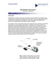
Theory of OperationHow the MFC Plus
- Page 110 and 111:
External Interface ConnectionsPin A
- Page 112 and 113:
External Interface ConnectionsPin A
- Page 114 and 115:
External Interface ConnectionsA/D C
- Page 116 and 117:
Standard Plumbing DiagramsFigure D-
- Page 118 and 119:
Standard Plumbing DiagramsFigure D-
- Page 120 and 121:
Autosampler Method Editor4. Click O
- Page 122 and 123:
Autosampler Method EditorCreate an
- Page 124 and 125:
Autosampler Method Editor• Click
- Page 126 and 127:
Autosampler Method EditorTable E-2D
- Page 128 and 129:
Autosampler Method EditorNeedle Was
- Page 130 and 131:
Basic MethodsFigure F-2Advanced Met
- Page 132 and 133:
Basic MethodsFigure F-4LC Method Se
- Page 134 and 135:
Basic MethodsTrap-and-elute MethodF
- Page 136 and 137:
Basic MethodsFigure F-8LC Method Se
- Page 138 and 139:
Basic MethodsFigure F-10 LC Method
- Page 140 and 141:
Basic MethodsFigure F-12 LC Method
- Page 142 and 143:
Basic MethodsFigure F-14 Run Manage
- Page 144 and 145:
Basic Methodsekspert nanoLC 400 Sys
- Page 146 and 147:
Working with Analyst® SoftwareVeri
- Page 148 and 149:
Working with Analyst® SoftwareFigu
- Page 150 and 151:
Working with Analyst® SoftwareFigu
- Page 152 and 153:
Working with Analyst® Softwareeksp
- Page 154 and 155:
2-D Reverse-phase/Reverse-phase Liq
- Page 156 and 157:
2-D Reverse-phase/Reverse-phase Liq
- Page 158 and 159:
2-D Reverse-phase/Reverse-phase Liq
- Page 160 and 161:
2-D Reverse-phase/Reverse-phase Liq
- Page 162 and 163:
2-D Reverse-phase/Reverse-phase Liq
- Page 164 and 165:
2-D Reverse-phase/Reverse-phase Liq
- Page 166 and 167:
2-D Reverse-phase/Reverse-phase Liq
- Page 168 and 169:
2-D Reverse-phase/Reverse-phase Liq
- Page 170 and 171:
2-D Reverse-phase/Reverse-phase Liq
- Page 172 and 173:
IndexFflow calibration assembly 36f
- Page 174:
Indextimer 36torque wrench 28traces