direct-vent fireplace (natural/propane/lp) - Desa
direct-vent fireplace (natural/propane/lp) - Desa
direct-vent fireplace (natural/propane/lp) - Desa

Create successful ePaper yourself
Turn your PDF publications into a flip-book with our unique Google optimized e-Paper software.
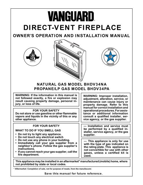
DIRECT-VENT FIREPLACE<br />
OWNER’S OPERATION AND INSTALLATION MANUAL<br />
®<br />
NATURAL GAS MODEL BHDV34NA<br />
PROPANE/LP GAS MODEL BHDV34PA<br />
WARNING: If the information in this manual is<br />
not followed exactly, a fire or explosion may<br />
result causing property damage, personal injury,<br />
or loss of life.<br />
FOR YOUR SAFETY<br />
Do not store or use gasoline or other flammable<br />
vapors and liquids in the vicinity of this or any<br />
other appliance.<br />
FOR YOUR SAFETY<br />
WHAT TO DO IF YOU SMELL GAS<br />
• Do not try to light any appliance.<br />
• Do not touch any electrical switch<br />
• Do not use any phone in your building.<br />
• Immediately call your gas supplier from a<br />
neighbor’s phone. Follow the gas supplier’s<br />
instructions.<br />
• If you cannot reach your gas supplier, call the<br />
fire department.<br />
WARNING: Improper installation,<br />
adjustment, alteration, service, or<br />
maintenance can cause injury or<br />
property damage. Refer to this<br />
manual for correct installation and<br />
operational procedures. For assistance<br />
or additional information<br />
consult a qualified installer, service<br />
agency, or the gas supplier.<br />
— Installation and service must<br />
be performed by a qualified installer,<br />
service agency, or the gas<br />
supplier.<br />
— This appliance is only for use<br />
with the type of gas indicated on<br />
the rating plate. This appliance is<br />
not convertible for use with other<br />
gases, unless a certified kit is<br />
used.<br />
This appliance may be installed in an aftermarket* manufactured (mobile) home, where<br />
not prohibited by state or local codes.<br />
* Aftermarket: Completion of sale, not for purpose of resale, from the manufacurer.<br />
Save this manual for future reference.
BHDV34NA, PA<br />
®<br />
DIRECT-VENT FIREPLACE (NATURAL/PROPANE/LP)<br />
SAFETY<br />
INFORMATION<br />
WARNINGS<br />
IMPORTANT: Read this owner’s<br />
manual carefully and completely<br />
before trying to assemble, operate,<br />
or service this <strong>fireplace</strong>. Improper<br />
use of this <strong>fireplace</strong> can<br />
cause serious injury or death from<br />
burns, fire, explosions, electrical<br />
shock, and carbon monoxide<br />
poisoning.<br />
DANGER: Carbon monoxide<br />
poisoning may lead to death!<br />
This <strong>fireplace</strong> is a <strong>vent</strong>ed product. This<br />
<strong>fireplace</strong> will not produce any gas leakage<br />
into your home if properly installed. This<br />
<strong>fireplace</strong> must be properly installed by a<br />
qualified service person. The glass door<br />
must be properly seated and sealed. If this<br />
unit is not properly installed by a qualified<br />
service person with glass door properly<br />
seated and sealed, gas leakage can occur.<br />
Carbon Monoxide Poisoning: Early signs<br />
of carbon monoxide poisoning resemble the<br />
flu, with headaches, dizziness, or nausea. If<br />
you have these signs, the <strong>fireplace</strong> may not<br />
have been installed properly. Get fresh air<br />
at once! Have <strong>fireplace</strong> inspected and serviced<br />
by a qualified service person. Some<br />
people are more affected by carbon monoxide<br />
than others. These include pregnant<br />
women, people with heart or lung disease or<br />
anemia, those under the influence of alcohol,<br />
and those at high altitudes.<br />
Propane/LP gas and <strong>natural</strong> gas are both<br />
odorless. An odor-making agent is added to<br />
each of these gases. The odor he<strong>lp</strong>s you<br />
detect a gas leak. However, the odor added<br />
to these gases can fade. Gas may be present<br />
even though no odor exists.<br />
Make certain you read and understand all<br />
warnings. Keep this manual for reference. It<br />
is your guide to safe and proper operation of<br />
this <strong>fireplace</strong>.<br />
WARNING: Any change to<br />
this <strong>fireplace</strong> or its controls can<br />
be dangerous.<br />
1. This appliance is only for use with the<br />
type of gas indicated on the rating plate.<br />
This appliance is not convertible for use<br />
with other gases unless a certified kit<br />
is used.<br />
2. For <strong>propane</strong>/LP <strong>fireplace</strong>, do not place<br />
<strong>propane</strong>/LP supply tank(s) inside any<br />
structure. Locate <strong>propane</strong>/LP supply<br />
tank(s) outdoors. To pre<strong>vent</strong> performance<br />
problems, do not use <strong>propane</strong>/LP<br />
fuel tank of less than 100 lbs. capacity.<br />
3. If you smell gas<br />
• shut off gas supply<br />
• do not try to light any appliance<br />
• do not touch any electrical switch; do<br />
not use any phone in your building<br />
• immediately call your gas supplier<br />
from a neighbor’s phone. Follow the<br />
gas supplier’s instructions<br />
• if you cannot reach you gas supplier,<br />
call the fire department.<br />
4. Never install the <strong>fireplace</strong><br />
• in a recreational vehicle<br />
• where curtains, furniture, clothing, or<br />
other flammable objects are less than<br />
42" from the front, top, or sides of<br />
the <strong>fireplace</strong><br />
• in high traffic areas<br />
• in windy or drafty areas<br />
5. This <strong>fireplace</strong> reaches high temperatures.<br />
Keep children and adults away<br />
from hot surfaces to avoid burns or clothing<br />
ignition. Fireplace will remain hot<br />
for a time after shutdown. Allow surfaces<br />
to cool before touching.<br />
6. Carefully supervise young children<br />
when they are in the room with <strong>fireplace</strong>.<br />
7. Do not modify this <strong>fireplace</strong> under any<br />
circumstances. Any parts removed for<br />
servicing must be replaced prior to operating<br />
<strong>fireplace</strong>.<br />
8. Turn <strong>fireplace</strong> off and let cool before<br />
servicing, installing, or repairing. Only<br />
a qualified service person should install,<br />
service, or repair this <strong>fireplace</strong>.<br />
Have <strong>fireplace</strong> inspected annually by a<br />
qualified service person.<br />
9. You must keep control compartments,<br />
burners, and circulating air passages<br />
clean. More frequent cleaning may be<br />
needed due to excessive lint and dust<br />
from carpeting, bedding material, pet<br />
hair, etc. Turn off the gas valve and pilot<br />
light before cleaning <strong>fireplace</strong>.<br />
10. Have <strong>vent</strong>ing system inspected annually<br />
by a qualified service person. If<br />
needed, have <strong>vent</strong>ing system cleaned<br />
or repaired. See Cleaning and Maintenance,<br />
page 28.<br />
11. Keep the area around your <strong>fireplace</strong><br />
clear of combustible materials, gasoline,<br />
and other flammable vapor and<br />
liquids. Do not run <strong>fireplace</strong> where<br />
these are used or stored. Do not place<br />
items such as clothing or decorations<br />
on or around <strong>fireplace</strong>.<br />
12. Do not use this <strong>fireplace</strong> to cook food<br />
or burn paper or other objects.<br />
13. Do not use any solid fuels (wood, coal,<br />
paper, cardboard, etc.) in this <strong>fireplace</strong>.<br />
Use only the gas type indicated on <strong>fireplace</strong><br />
nameplate.<br />
14. This appliance, when installed, must be<br />
electrically grounded in accordance<br />
with local codes or, in the absence of<br />
local codes, with the National Electrical<br />
Code, ANS/NFPA 70, or the Canadian<br />
Electrical Code, CSA C22.1.<br />
15. Do not obstruct the flow of combustion<br />
and <strong>vent</strong>ilation air in any way. Provide<br />
adequate clearances around air<br />
openings into the combustion chamber<br />
along with adequate accessibility clearance<br />
for servicing and proper operation.<br />
16. Do not install <strong>fireplace</strong> <strong>direct</strong>ly on carpeting,<br />
vinyl tile, or any combustible<br />
material other than wood. The <strong>fireplace</strong><br />
must set on a metal or wood panel extending<br />
the full width and depth of the<br />
<strong>fireplace</strong>.<br />
17. Do not use <strong>fireplace</strong> if any part has been<br />
exposed to or under water. Immediately<br />
call a qualified service person to arrange<br />
for replacement of the unit.<br />
18. Do not operate <strong>fireplace</strong> if any log is<br />
broken.<br />
19. Do not use a blower insert, heat exchanger<br />
insert, or other accessory not<br />
approved for use with this <strong>fireplace</strong>.<br />
20. Do not operate <strong>fireplace</strong> with glass door<br />
removed, cracked, or broken.<br />
2 105981
OWNER’S MANUAL<br />
PRODUCT<br />
IDENTIFICATION<br />
Top Louver<br />
Panel<br />
Nailing<br />
Flange<br />
Glass Door<br />
Assembly<br />
Lower Louver<br />
Panel<br />
Piezo Ignitor<br />
Valve<br />
Glowing Embers<br />
Blower Adjustment<br />
(Optional Installation)<br />
Vent Opening<br />
Figure 1 - Vanguard Direct-Vent Fireplace BHDV Series<br />
Standoff<br />
Log Set<br />
Pilot Assembly<br />
Burner<br />
Grate Assembly<br />
Lava Rock<br />
LOCAL CODES<br />
Install and use <strong>fireplace</strong> with care. Follow<br />
all local codes. In the absence to local codes,<br />
use the current National Fuel Gas Code<br />
ANS Z223.1, also known as NFPA 54*<br />
(USA) or the current CAN/CGA-B149[.1 or<br />
.2] Installation Codes (Canada).<br />
*Available from:<br />
American National Standards Institute, Inc.<br />
1430 Broadway<br />
New York, NY 10018<br />
National Fire Protection Association, Inc.<br />
Batterymarch Park<br />
Quincy, MA 02269<br />
PRODUCT<br />
FEATURES<br />
OPERATION<br />
This <strong>direct</strong>-<strong>vent</strong> <strong>fireplace</strong> is clean burning<br />
and <strong>vent</strong>s easily through outside walls or<br />
vertically using outside air for combustion.<br />
Heat is generated by both realistic flames<br />
and glowing embers. When used without<br />
the blower accessory, the <strong>fireplace</strong> requires<br />
no electricity making it ideal for emergency<br />
backup heat.<br />
PIEZO IGNITOR<br />
This <strong>fireplace</strong> has a piezo ignitor. This system<br />
requires no matches, batteries, or other<br />
sources to light <strong>fireplace</strong>.<br />
GLOSSARY OF<br />
TERMS<br />
Chase - A boxlike enclosure to protect<br />
<strong>vent</strong>ing from the elements when the <strong>vent</strong>ing<br />
run is on the outside of a structure.<br />
Mastic - A pliable sealant for use around the<br />
<strong>vent</strong> terminal.<br />
Snorkel Termination - A box that raises the<br />
horizontal termination above ground level<br />
clearances.<br />
Vent Terminal - Mounted on an outside<br />
wall or roof to separate the inlet and outlet of<br />
the <strong>vent</strong> system and protect it from weather.<br />
Vinyl Siding Standoff - A metal box that<br />
separates the <strong>vent</strong> cap from vinyl siding.<br />
Wall Thimble/Firestop - A metal plate used<br />
to secure the <strong>vent</strong> pipe when it passes through<br />
a wall or ceiling.<br />
105981<br />
3
BHDV34NA, PA<br />
®<br />
DIRECT-VENT FIREPLACE (NATURAL/PROPANE/LP)<br />
PRE-INSTALLATION<br />
PREPARATION<br />
LOCATION AND SPACE<br />
REQUIREMENTS<br />
Determine the safest and most efficient location<br />
for your Vanguard <strong>direct</strong>-<strong>vent</strong> <strong>fireplace</strong>.<br />
Make sure that rafters and wall studs are not<br />
in the way of the <strong>vent</strong>ing system. Choose a<br />
location where the heat output is not affected<br />
by drafts, air conditioning ducts, windows or<br />
doors. Figure 2 shows some common locations.<br />
Read all <strong>vent</strong>ing information in this<br />
manual. Be aware of all restrictions and<br />
precautions before deciding the exact location<br />
for your <strong>fireplace</strong>.<br />
When deciding the location of your <strong>fireplace</strong>,<br />
follow these rules:<br />
1. Do not connect this <strong>fireplace</strong> to a chimney<br />
flue serving a separate solid-fuel<br />
burning <strong>fireplace</strong> or appliance.<br />
2. Due to high temperatures, do not locate<br />
this <strong>fireplace</strong> in high traffic areas<br />
or near furniture or draperies.<br />
3. Proper clearances must be maintained.<br />
4. If your <strong>fireplace</strong> is to be installed <strong>direct</strong>ly<br />
on carpeting, vinyl tile, or any<br />
combustible material other than wood,<br />
it must be installed on a metal or wood<br />
panel extending the full width and<br />
depth of the <strong>fireplace</strong>. See Figure 3.<br />
CLEARANCES<br />
Minimum clearances to combustibles for<br />
the <strong>fireplace</strong> are as follows:<br />
Back, and sides<br />
0"/mm<br />
Perpendicular walls 6" (152mm)<br />
Floor<br />
0"/mm<br />
Ceiling to louver opening 42" (1067mm)<br />
Front<br />
36" (914mm)<br />
Top of Standoffs 0"/mm<br />
See General Venting on page 5 for specific<br />
<strong>vent</strong>ing clearances.<br />
FRAMING AND FINISHING<br />
Figures 4 and 5 show typical framing of this<br />
<strong>fireplace</strong>. Figure 6 on page 5 shows framing<br />
for corner installation. All minimum clearances<br />
must be met. Do not install <strong>fireplace</strong><br />
<strong>direct</strong>ly on carpeting, vinyl tile, or any combustible<br />
material other than wood. The <strong>fireplace</strong><br />
must set on a metal or wood panel<br />
extending the full width and depth of the<br />
<strong>fireplace</strong>.<br />
See Accessories on pages 34 and 35 for<br />
mantel kits available for this <strong>fireplace</strong>. If you<br />
are using a separate combustible mantel piece,<br />
refer to Figure 7 on page 5 for proper installation<br />
height. You can install noncombustible<br />
mantels at any height above the <strong>fireplace</strong>.<br />
Note: Noncombustible mantels may discolor!<br />
Must maintain a minimum<br />
1" clearance to combustibles<br />
34"<br />
20"<br />
5/8" for drywall facing<br />
Figure 5 - Framing Clearances for Typical<br />
Fireplace Installation<br />
Flush with a wall<br />
Through exterior wall<br />
enclosed in a chase<br />
Figure 2 - Common Fireplace Locations<br />
D<br />
RW<br />
FW<br />
Corner<br />
installation<br />
Fireplace size D x FW x RW<br />
34" 18 1 /2" 34 3 /8" 14"<br />
34 1 /4"<br />
34 3 /4"<br />
20" Vertical Termination<br />
19" Horizontal Termination<br />
Figure 3 - Fireplace Bottom Dimensions<br />
Figure 4 - Framing Clearances for Installation Against an Exterior Wall<br />
4 105981
PRE-INSTALLATION<br />
PREPARATION<br />
Continued<br />
29"<br />
105981<br />
13"<br />
12 5 /8"<br />
58"<br />
34 3 /8"<br />
9 1 /4" 41"<br />
35 1 /16"<br />
Figure 6 - Framing Clearances for Corner Installation<br />
Note: There must be<br />
a minimum clearance<br />
of 18" above<br />
top of louver<br />
opening when<br />
installing a television<br />
or entertainment<br />
center above the<br />
<strong>fireplace</strong>.<br />
A<br />
Top of Louver Opening<br />
Ref. Mantel Depth Ref. Mantel from Top<br />
of Louver Opening<br />
1 14" (356mm) A 16" (406mm)<br />
2 12" (305mm) B 14" (356mm)<br />
3 10" (254mm) C 12" (305mm)<br />
4 8" (203mm) D 10" (254mm)<br />
5 6" (152mm) E 8" (203mm)<br />
6 4" (101mm) F 6" (152mm)<br />
7 2" (51mm) G 4" (101mm)<br />
Figure 7 - Clearances for Combustible Mantels<br />
B<br />
C<br />
D<br />
E<br />
F<br />
G<br />
1<br />
2<br />
3<br />
4<br />
5<br />
6<br />
7<br />
Nailing Tabs<br />
Wall<br />
5<br />
OWNER’S MANUAL<br />
GENERAL VENTING<br />
These models are approved for use with<br />
Simpson Dura-Vent 6 5 /8" <strong>direct</strong>-<strong>vent</strong> pipe<br />
components and terminations as well as both<br />
flex and rigid Vanguard <strong>vent</strong> components.<br />
Your <strong>fireplace</strong> is approved to be <strong>vent</strong>ed either<br />
through the side wall, or vertically using the<br />
following guidelines:<br />
• Only use Vanguard or Simpson Dura-<br />
Vent GS <strong>vent</strong>ing components or kits specifically<br />
approved for this <strong>fireplace</strong>.<br />
• Minimum clearance between <strong>vent</strong> pipes<br />
and combustible materials is 1" (25 mm),<br />
except where stated otherwise.<br />
• Combustible material may be flush with<br />
the top front of <strong>fireplace</strong> with a maximum<br />
thickness of 3/4".<br />
• Do not recess <strong>vent</strong>ing terminals into a<br />
wall or siding.<br />
• Install horizontal <strong>vent</strong>ing with a 1/4" rise for<br />
every 12" of run toward the termination.<br />
• You may paint the <strong>vent</strong> terminal with<br />
450ºF (232ºC) heat-resistant paint to coordinate<br />
with the exterior finish.<br />
• There must not be any obstruction such<br />
as bushes, garden sheds, fences, decks,<br />
or utility buildings within 24" from the<br />
front of the termination cap.<br />
• Do not locate termination cap where excessive<br />
snow or ice build up may occur.<br />
Be sure to clear <strong>vent</strong> termination area after<br />
snow falls to pre<strong>vent</strong> accidental blockage<br />
of <strong>vent</strong>ing system. When using snow<br />
blowers, do not <strong>direct</strong> snow towards <strong>vent</strong><br />
termination area.<br />
LOCATION OF VENT<br />
TERMINATION<br />
When locating <strong>vent</strong> termination, it is important<br />
to observe the minimum clearances<br />
shown in Figure 8, page 6. You will avoid<br />
extra framing by positioning your <strong>fireplace</strong><br />
against an already existing framing member.<br />
The sides of the <strong>fireplace</strong> may be positioned<br />
<strong>direct</strong>ly against combustible walls.<br />
*Check with local codes or with the current<br />
CAN/CGA B149 [.1 or .2] Installation Codes<br />
for Canada or the USA Installations follow<br />
the current National Fuel Gas Code, ANS<br />
Z223.1, also known as NFPA 54.<br />
Continued
BHDV34NA, PA<br />
®<br />
DIRECT-VENT FIREPLACE (NATURAL/PROPANE/LP)<br />
GENERAL VENTING Continued<br />
N<br />
N<br />
D<br />
H<br />
V<br />
E<br />
L<br />
B<br />
F<br />
V<br />
C<br />
Fixed<br />
B<br />
Closed<br />
V<br />
Openable Fixed<br />
Closed<br />
Openable<br />
B<br />
B<br />
V<br />
A<br />
J<br />
X<br />
B<br />
V<br />
G<br />
I<br />
M<br />
V<br />
K<br />
X<br />
G<br />
G<br />
V<br />
V<br />
V<br />
TERMINATION CAP X AIR SUPPLY INLET G GAS METER RESTRICTED AREA<br />
(TERMINATION PROHIBITED)<br />
I = clearance to service regulator <strong>vent</strong> outlet [*72 inches (1829mm)<br />
minimum]<br />
A = clearance above grade, veranda, porch, deck, or balcony<br />
[*12 inches (305mm) minimum]<br />
B = clearance to window or door that may be opened<br />
[12 inches (305mm) minimum]<br />
C = clearance to permanently closed window [minimum 12 inches<br />
(305mm) recommended to pre<strong>vent</strong> condensation on window]<br />
D = vertical clearance to <strong>vent</strong>ilated soffit located above the terminal<br />
within a horizontal distance of 24 inches (610mm) from the<br />
center-line of the terminal [18 inches (457mm) minimum]<br />
E = clearance to un<strong>vent</strong>ilated soffit [12 inches (305mm) minimum]<br />
F = clearance to outside corner (see below)<br />
G = clearance to inside corner (see below)<br />
H = *not to be installed above a meter/regulator assembly within<br />
36 inches (914mm) horizontally from the center-line of the regulator<br />
J = clearance to non-mechanical air supply inlet to building or the<br />
combustion air inlet to any other <strong>fireplace</strong> [*12 inches (305mm)<br />
minimum]<br />
K = clearance to a mechanical air supply inlet [*72 inches (1829mm)<br />
minimum]<br />
L = † clearance above paved side-walk or a paved driveway located on<br />
public property [*84 inches (2133mm) minimum]<br />
M = clearance under veranda, porch, deck [*12 inches (305mm) minimum ‡]<br />
N = clearance above a roof shall extend a minimum of 24 inches (610mm)<br />
above the highest point when it passes through the roof surface and<br />
any other obstruction within a horizontal distance of 18 inches (457mm)<br />
† <strong>vent</strong> shall not terminate <strong>direct</strong>ly above a side-walk or paved driveway which is located between two<br />
single family dwellings and serves both dwellings*<br />
‡ only permitted if veranda, porch, deck or balconey is fully open on a minimum of 2 sides beneath the floor*<br />
* as specified in CAN/SGA B149 (.1 or .2) Installation Codes (1991) for Canada or for U.S.A. installation follow<br />
the current National Fuel Gas Code, ANS Z223.1<br />
Note: Local codes or regulations may require different clearances<br />
Termination Clearances for Buildings with Combustible and Noncombustible Exteriors<br />
Inside Corner<br />
Outside Corner<br />
Recessed Location<br />
A<br />
D<br />
A<br />
A = 6" (152mm)<br />
C<br />
E<br />
C<br />
V<br />
V<br />
V<br />
B<br />
B = 6" (152mm)<br />
Balcony with No Side Wall<br />
Balcony with Perpendicular Side Wall<br />
G<br />
V<br />
G = Combustible 24" (610mm)<br />
Noncombustible 18" (457mm)<br />
H<br />
V<br />
Combustible &<br />
Noncombustible<br />
H = 24" (610mm)<br />
J = 20" (508mm)<br />
Figure 8 - Minimum Clearances for Vent Terminations<br />
J<br />
C = Maximum depth of 48" (1219mm) for<br />
recessed location<br />
D = Minimum width for back wall of<br />
recessed location -<br />
Combustible - 38" (965mm)<br />
Noncombustible - 24" (610mm)<br />
E = Clearance from corner in<br />
recessed location-<br />
Combustible - 6" (152mm)<br />
Noncombustible - 2" (51mm)<br />
6 105981
OWNER’S MANUAL<br />
VENTING<br />
INSTALLATION<br />
WARNING: Read all instructions<br />
completely and thoroughly<br />
before attempting installation.<br />
Failure to do so could result in<br />
serious injury, property damage<br />
or loss of life. Operation of improperly<br />
installed and maintained<br />
<strong>vent</strong>ing system could result in<br />
serious injury, property damage<br />
or loss of life.<br />
WARNING: Seal all <strong>vent</strong> connections.<br />
Seal only the outer pipe<br />
connections with high temperature<br />
silicone (600°F/316° C). Before joining<br />
elbows and pipes, apply a bead<br />
of high temperature silicone sealant<br />
(GE RTV 106/Loctite RTV 81585)<br />
to the male end of the elbow or<br />
pipe. High temperature silicone<br />
must also be used to re-seal any<br />
connections after maintenance to<br />
<strong>vent</strong>ing system.<br />
NOTICE: Failure to follow these<br />
instructions will void the warranty.<br />
INSTALLATION<br />
PRECAUTIONS<br />
Consult local building codes before beginning<br />
the installation. The installer must make sure<br />
to select the proper <strong>vent</strong> system for installation.<br />
Before installing <strong>vent</strong> kit, the installer<br />
must read this <strong>fireplace</strong> manual and <strong>vent</strong> kit<br />
instructions.<br />
Only a qualified service person should install<br />
<strong>vent</strong>ing system. The installer must follow<br />
these safety rules:<br />
• Wear gloves and safety glasses for<br />
protection<br />
• Use extreme caution when using ladders<br />
or when on roof tops<br />
• Be aware of electrical wiring locations<br />
in walls and ceilings<br />
The following actions will void the warranty<br />
on your <strong>vent</strong>ing system:<br />
• Installation of any damaged <strong>vent</strong>ing<br />
component<br />
• Unauthorized modification of the <strong>vent</strong>ing<br />
system<br />
105981<br />
• Installation of any component part not<br />
manufactured or approved by DESA<br />
International<br />
• Installation other than as instructed by<br />
these instructions<br />
WARNING: This gas <strong>fireplace</strong><br />
and <strong>vent</strong> assembly must be<br />
<strong>vent</strong>ed <strong>direct</strong>ly to the outside.<br />
The <strong>vent</strong>ing system must NEVER<br />
be attached to a chimney serving<br />
a separate solid fuel burning appliance.<br />
Each gas appliance must<br />
use a separate <strong>vent</strong> system. Do<br />
not use common <strong>vent</strong> systems.<br />
WARNING: Horizontal sections<br />
of this <strong>vent</strong> system require<br />
a minimum clearance of 2" from<br />
the top of the pipe and 1" minimum<br />
to the sides and bottom.<br />
Vertical sections of this system<br />
require a minimum of 1" clearance<br />
to combustible materials on<br />
all sides of the pipe.<br />
INSTALLATION PLANNING<br />
There are two basic types of <strong>direct</strong>-<strong>vent</strong><br />
installation:<br />
• Horizontal Termination<br />
• Vertical Termination<br />
It is important to select the proper length of<br />
<strong>vent</strong> pipe for the type of termination you<br />
choose. It is also important to note the wall<br />
thickness.<br />
For Horizontal Termination: Select the<br />
amount of vertical rise desired. The horizontal<br />
run of <strong>vent</strong>ing must have 1/4" rise for<br />
every 12" of run towards the termination.<br />
WARNING: Never run the <strong>vent</strong><br />
downward as this may cause excessive<br />
temperatures which<br />
could cause a fire.<br />
You may use one or two 90° elbows in this<br />
<strong>vent</strong> configuration. See Horizontal Termination<br />
Configurations on pages 10 and 11.<br />
For Vertical Termination: Measure the distance<br />
from the <strong>fireplace</strong> flue outlet to the<br />
ceiling. Add the ceiling thickness, the vertical<br />
rise in an attic or second story, and allow<br />
for sufficient <strong>vent</strong> height above the roofline.<br />
7<br />
You may use one or two 90° elbows in this<br />
<strong>vent</strong> configuration. See Vertical Termination<br />
Configurations on pages 13 and 14.<br />
Note: You may use two 45° elbows in place<br />
of a 90° elbow. You must follow rise to run<br />
ratios when using 45° elbows.<br />
For two-story applications, firestops are required<br />
at each floor level. If an offset is<br />
needed in the attic, additional pipe and elbows<br />
will be required.<br />
You may use a chase with a <strong>vent</strong> termination<br />
with exposed pipe on the exterior of the<br />
house. See Installing Vent System in a Chase,<br />
below.<br />
Your Vanguard <strong>direct</strong>-<strong>vent</strong> <strong>fireplace</strong> has<br />
been tested for a minimum 3' rise with a<br />
maximum 10" wall thickness. The maximum<br />
horizontal run is 20' with 8' vertical<br />
rise (see Installation for Horizontal Termination,<br />
page 8). The maximum vertical run<br />
is 30' (see Installation for Vertical Termination,<br />
page 12).<br />
It is very important that the <strong>vent</strong>ing system<br />
maintain its balance between the combustion<br />
air intake and the flue gas exhaust.<br />
Certain limitations apply to <strong>vent</strong> configurations<br />
and must be strictly followed.<br />
Installing Vent System in a Chase<br />
A chase is a vertical boxlike structure built<br />
to enclose <strong>vent</strong>ing that runs along the outside<br />
of a building. A chase is not required for<br />
such <strong>vent</strong>ing.<br />
NOTICE: Treatment of firestops<br />
and construction of the chase may<br />
vary from building type to building<br />
type. These instructions are<br />
not substitutes for the requirements<br />
of local building codes. You<br />
must follow all local building<br />
codes.<br />
Note: When installing in a chase, you should<br />
insulate the chase as you would the outside<br />
walls of your home. This is especially important<br />
in cold climates. Minimum clearance<br />
between <strong>vent</strong> pipes and combustible<br />
materials such as insulation is 1".<br />
After framing the chase (see Framing and<br />
Finishing on pages 4 and 5) install the<br />
<strong>vent</strong> system by following the installation<br />
instructions.<br />
Continued
BHDV34NA, PA<br />
®<br />
DIRECT-VENT FIREPLACE (NATURAL/PROPANE/LP)<br />
VENTING<br />
INSTALLATION<br />
Continued<br />
INSTALLATION FOR<br />
HORIZONTAL TERMINATION<br />
1. Determine the route your horizontal<br />
<strong>vent</strong>ing will take. Note: The location<br />
of the horizontal <strong>vent</strong> termination on<br />
the exterior wall must meet all local and<br />
national building codes and must not<br />
be easily blocked or obstructed.<br />
Snorkel<br />
12" Minimum<br />
To Ground Level<br />
WARNING: Do not recess <strong>vent</strong><br />
terminal into a wall or siding.<br />
Snorkel terminations are available for<br />
terminations requiring a vertical rise on<br />
the exterior of the building (see Figures<br />
9 and 10). Snorkel kit SVK is also available<br />
(see page 15). Follow the same installation<br />
procedures used for standard<br />
horizontal terminations. If installing the<br />
snorkel termination below grade (basement<br />
applications), you must provide<br />
proper drainage to pre<strong>vent</strong> water from<br />
entering the snorkel termination (see<br />
Figure 10). Do not back fill around the<br />
snorkel termination.<br />
2. Rigid <strong>vent</strong> pipes and fittings have special<br />
twist-lock connections. Assemble<br />
the desired combination of pipe and elbows<br />
to the appliance adaptor with pipe<br />
seams oriented towards the wall or floor.<br />
Twist-lock Procedure: The female<br />
ends of the pipes and fittings have four<br />
locking lugs (indentations). These lugs<br />
will slide straight into matching slots on<br />
the male ends of adjacent pipes and fittings.<br />
(All connections must be sealed<br />
with high temperature silicone sealant<br />
as specified in the second warning statement<br />
on page 7.) Push the pipe sections<br />
together and twist one section clockwise<br />
approximately one-quarter turn until the<br />
sections are fully locked. See Figure 11,<br />
page 9. Note: Horizontal runs of <strong>vent</strong><br />
must be supported every three feet. Use<br />
wall straps for this purpose.<br />
Flexible <strong>vent</strong> pipe must be installed with<br />
spacer springs every 12". See Figure 11,<br />
page 9. All connections must be clamped<br />
tightly and sealed with high temperature<br />
silicone sealant as specified in the second<br />
warning statement on page 7.<br />
,,,,,<br />
,,,,,<br />
,,,,,<br />
Figure 9 - Snorkel Termination ,,,,,<br />
Snorkel<br />
Adequate drainage<br />
,,,,,,,,,,,,,,<br />
,,,,,,,,,,,,,,<br />
,,,,,,,,,,,,,,<br />
,,,,,,,,,,,,,,<br />
,,,,,,,,,,,,,,<br />
,,,,,,,,,,,,,,<br />
,,,,,,,,,,,,,,<br />
Figure 10 - Snorkel Termination with Drainage Pipe<br />
12" Minimum<br />
To Ground Level<br />
8 105981
OWNER’S MANUAL<br />
VENTING<br />
INSTALLATION<br />
Continued<br />
3. Attach <strong>vent</strong> pipe assembly to the <strong>fireplace</strong>.<br />
Set <strong>fireplace</strong> in front of it’s permanent<br />
location to insure minimum<br />
clearances. Mark the wall for a 10"<br />
square hole (for noncombustible material<br />
such as masonry block or concrete,<br />
a 7 1 /2" diameter hole is acceptable).<br />
See Figure 12. The center of the<br />
hole should line up with the centerline<br />
of the horizontal rigid <strong>vent</strong> pipe.<br />
Cut a 10"x10" (254mm x 254mm)<br />
square hole through combustible exterior<br />
wall (7 1 /2" [190mm] diameter<br />
hole if noncombustible). Frame as necessary<br />
(see Figure 12).<br />
Female<br />
Locking<br />
Lugs<br />
Male<br />
Slots<br />
4" Clamp<br />
7" Clamp<br />
Spacer<br />
Spring<br />
4" Flex<br />
Pipe<br />
7" Flex<br />
Pipe<br />
4. Apply a bead of non-hardening mastic<br />
around the outside edge of the <strong>vent</strong> cap.<br />
Position the <strong>vent</strong> cap in the center of<br />
the 7 1 /2" or 10" hole on the exterior<br />
wall with the arrow on the <strong>vent</strong> cap<br />
pointing up. Insure proper clearance of<br />
1" to combustibles is maintained. Attach<br />
the <strong>vent</strong> cap with four wood screws<br />
supplied (see Figure 13). Note: Replace<br />
the wood screws with appropriate<br />
fasteners for stucco, brick, concrete,<br />
or other types of siding.<br />
WARNING: Do not recess <strong>vent</strong><br />
termination in to any wall. This<br />
will cause a fire hazard.<br />
For vinyl siding use vinyl siding standoffs<br />
between <strong>vent</strong> cap and exterior wall.<br />
The vinyl siding standoff pre<strong>vent</strong>s excessive<br />
heat from melting the vinyl siding<br />
material. Bolt the <strong>vent</strong> cap to the<br />
standoff. Apply non-hardening mastic<br />
around outside edge of the standoff instead<br />
of the <strong>vent</strong> cap assembly. Use<br />
wood screws provided to attach the<br />
standoff. See Figure 14.<br />
5. Slide the wall thimble over the <strong>vent</strong> pipe<br />
before connecting the horizontal run to<br />
the <strong>vent</strong> cap (see Figure 15).<br />
6. Carefully move the <strong>fireplace</strong> with <strong>vent</strong><br />
assembly attached toward the wall and<br />
insert the <strong>vent</strong> pipe into the horizontal<br />
termination. The pipe overlap should<br />
be a minimum of 1 1 /4". Apply silicone<br />
to the outer pipe connection. Fasten all<br />
<strong>vent</strong> connections with screws provided.<br />
Refer to Fireplace Installation on page<br />
16 for instructions on securing unit to<br />
framing or floor.<br />
7. Slide the wall thimble against the interior<br />
wall surface and attach with screws<br />
provided (see Figure 15).<br />
Cut Vinyl Siding<br />
Away to Fit<br />
Standoff<br />
Wood Screw<br />
Standoff<br />
Nut<br />
Bolt<br />
Apply Mastic<br />
to All Four Sides Vent Cap<br />
Figure 14 - Installing Vinyl Siding Standoff<br />
UP<br />
Rigid Vent Pipe<br />
Flexible Vent Pipe<br />
Figure 11 - Vent Pipe Connections<br />
Apply Mastic<br />
to All Four<br />
Sides<br />
Interior Wall<br />
Surface<br />
Vent Opening<br />
Combustible Wall<br />
10"<br />
(254mm)<br />
UP<br />
Wall<br />
Thimble<br />
10"<br />
(254mm)<br />
Vent Cap<br />
Wood<br />
Screw<br />
Vent Opening<br />
Noncombustible Wall<br />
7 1 /2"<br />
(190mm)<br />
(Framing<br />
Detail)<br />
Figure 13 - Installing Horizontal Vent Cap<br />
Vent Cap<br />
(Horizontal Screw<br />
Termination)<br />
Horizontal<br />
Vent Pipe<br />
Figure 15 - Connecting Vent Cap with<br />
Horizontal Vent Pipe<br />
Figure 12 - Vent Opening Requirements<br />
Continued<br />
105981<br />
9
BHDV34NA, PA<br />
®<br />
DIRECT-VENT FIREPLACE (NATURAL/PROPANE/LP)<br />
VENTING<br />
INSTALLATION<br />
Continued<br />
Horizontal Termination<br />
Configurations<br />
Figures 16 through 20 show different configurations<br />
for <strong>vent</strong>ing with horizontal termination.<br />
Each figure includes a chart with<br />
vertical minimum/maximum and horizontal<br />
maximum dimensions which must be<br />
met. Seal all connections with high temperature<br />
silicone sealant (outer pipe only) as<br />
specified in the second warning statement<br />
on page 7. All horizontal terminations require<br />
1/4" rise per 12" of horizontal run.<br />
Horizontal Venting<br />
Vertical (V) Horizontal (H)<br />
44" min. 29" max.<br />
(30° and 90° only, no vertical pipe)<br />
55" min. 41" max.<br />
(30° elbow, 1' vertical pipe, 90° elbow)<br />
67" min. 60" max.<br />
79" min. 84" max.<br />
96" min. 20' max.<br />
Note: This configuration for use with<br />
corner installation.<br />
UP<br />
BVK Vent Kit Shown<br />
Figure 17 - Horizontal Termination Configuration for Rigid Venting Using One<br />
90° Elbow<br />
UP<br />
Horizontal Venting<br />
BGFVK Vent Kit Shown<br />
(recommended for use<br />
with cabinet mantels)<br />
Horizontal Venting<br />
Vertical (V) Horizontal (H)<br />
37" min. 10" max.<br />
See information in<br />
Figure 17 for<br />
Vertical(V) and<br />
Horizontal(H) maximums<br />
and minimums.<br />
The same amounts<br />
apply for flexible<br />
<strong>vent</strong>ing.<br />
Note: Figure 16<br />
applies to rigid<br />
<strong>vent</strong>ing only.<br />
UP<br />
BFGFVK and FGFVK<br />
Vent Kits Shown<br />
Figure 16 - Horizontal Termination Configuration<br />
for Rigid Venting<br />
Figure 18 - Horizontal Termination Using Flexible Venting<br />
10 105981
OWNER’S MANUAL<br />
VENTING<br />
INSTALLATION<br />
Continued<br />
Venting with Two 90° Elbows<br />
Vertical (V) Horizontal (H 1<br />
) Horizontal (H 1<br />
) +<br />
Horizontal (H 2<br />
)<br />
5' min. 2' max. 6' max.<br />
6' min. 4' max. 12' max.<br />
7' min. 6' max. 18' max.<br />
8' min. 8' min. 20' max.<br />
UP<br />
20' max. 8' max. 20' max.<br />
Figure 19 - Horizontal Termination Configuration for Rigid Venting Using Two 90° Elbows<br />
Venting with Two 90° Elbows<br />
Vertical (V) Horizontal (H 1<br />
) +<br />
Horizontal (H 2<br />
)<br />
5' min. 6' max.<br />
6' min. 12' max.<br />
7' min. 18' max.<br />
8' min. 20' max.<br />
20' max. 20' max.<br />
Figure 20 - Horizontal Termination Configuration for Rigid Venting Using Two 90° Elbows with Termination at 90° with Fireplace<br />
Continued<br />
105981<br />
11
BHDV34NA, PA<br />
®<br />
DIRECT-VENT FIREPLACE (NATURAL/PROPANE/LP)<br />
VENTING<br />
INSTALLATION<br />
Continued<br />
INSTALLATION FOR<br />
VERTICAL TERMINATION<br />
NOTICE: Use rigid pipe only. Flex<br />
<strong>vent</strong>ing is not to be used with a<br />
vertical termination.<br />
1. Determine the route your vertical <strong>vent</strong>ing<br />
will take. If ceiling joists, roof<br />
rafters, or other framing will obstruct the<br />
<strong>vent</strong>ing system, consider an offset (see<br />
Figure 21) to avoid cutting load bearing<br />
members. Note: Pay special attention<br />
to these installation instructions for required<br />
clearances (air space) to combustibles<br />
when passing through ceilings,<br />
walls, roofs, enclosures, attic rafters, etc.<br />
Do not pack air spaces with insulation.<br />
Also note maximum vertical rise of the<br />
<strong>vent</strong>ing system and any maximum horizontal<br />
offset limitations. Offsets must<br />
fall within the parameters shown in<br />
Figure 8 on page 6.<br />
2. Set the <strong>fireplace</strong> in desired location.<br />
Drop a plumb line down from the ceiling<br />
to the position of the <strong>fireplace</strong> exit<br />
flue. Mark the center point where the<br />
<strong>vent</strong> will penetrate the ceiling. Drill a<br />
small locating hole at this point.<br />
Drop a plumb line from the inside of<br />
the roof to the locating hole in the ceiling.<br />
Mark the center point where the<br />
<strong>vent</strong> will penetrate the roof. Drill a<br />
small locating hole at this point.<br />
Wall Strap<br />
Roof<br />
Flashing<br />
45° Elbow<br />
Flat Ceiling Installation<br />
1. Cut a 10" square hole in the ceiling using<br />
the locating hole as a center point.<br />
The opening should be framed to<br />
10"x10" (254mm x 254mm) inside dimensions,<br />
as shown in Figure 12 on<br />
page 9 using framing lumber the same<br />
size as the ceiling joists. If the area<br />
above the ceiling is an insulated ceiling<br />
or a room, nail firestop from the<br />
top side. This pre<strong>vent</strong>s loose insulation<br />
from falling into the required clearance<br />
space. Otherwise, install firestop below<br />
the framed hole. The firestop should be<br />
installed with no less than three nails<br />
per side (see Figure 22).<br />
2. Assemble the desired lengths of pipe<br />
and elbows necessary to reach from the<br />
<strong>fireplace</strong> flue up through the firestop.<br />
All connections must be sealed with<br />
high temperature silicone sealant as<br />
specified in the second warning statement<br />
on page 7. Be sure all pipe and<br />
elbow connections are fully twistlocked<br />
(see Figure 11, page 9).<br />
3. Cut a hole in the roof using the locating<br />
hole as a center point. (Cover any exposed<br />
open <strong>vent</strong> pipes before cutting<br />
hole in roof.) The 10"x10" hole must<br />
be measured on the horizontal; actual<br />
length may be larger depending on the<br />
pitch of the roof. There must be a 1"<br />
clearance from the <strong>vent</strong> pipe to combustible<br />
materials. Frame the opening as<br />
shown in Figure 12 on page 9.<br />
If area above is a room, install firestop<br />
above framed hole.<br />
If area above is not a room, install<br />
firestop below framed hole.<br />
4. Connect a section of pipe and extend<br />
up through the hole.<br />
Note: If an offset is needed to avoid<br />
obstructions, you must support the <strong>vent</strong><br />
pipe every 3 feet. Use wall straps for<br />
this purpose (see Figure 21). Whenever<br />
possible, use 45° elbows instead of 90°<br />
elbows. The 45° elbow offers less restriction<br />
to the flow of the flue gases<br />
and intake air.<br />
5. Place the flashing over the pipe<br />
section(s) extending through the roof.<br />
Secure the base of the flashing to the<br />
roof and framing with roofing nails. Be<br />
sure roofing material overlaps the top<br />
edge of the flashing as shown in Figure<br />
21. There must be a 1" clearance from<br />
the <strong>vent</strong> pipe to combustible materials.<br />
6. Continue to add pipe sections until the<br />
height of the <strong>vent</strong> cap meets the minimum<br />
building code requirements described<br />
in Figure 8 on page 6. Note: You<br />
must increase <strong>vent</strong> height for steep roof<br />
pitches. Nearby trees, adjoining rooflines,<br />
steep pitched roofs, and other similar factors<br />
may cause poor draft or down-drafting<br />
in high winds. Increasing the <strong>vent</strong><br />
height may solve this problem.<br />
7. Twist-lock the <strong>vent</strong> cap onto the last<br />
section of <strong>vent</strong> pipe and seal outer pipe<br />
connection with high temperature silicone<br />
sealant as specified in the second<br />
warning statement on page 7.<br />
Note: If the <strong>vent</strong> pipe passes through any<br />
occupied areas above the first floor, including<br />
storage spaces and closets, you must enclose<br />
pipe. You may frame and sheetrock the enclosure<br />
with standard construction material. Make<br />
sure and meet the minimum allowable clearances<br />
to combustibles. Do not fill any of the<br />
required air spaces with insulation.<br />
Cathedral Ceiling Installation<br />
1. Remove shingles or other roof covering<br />
as necessary to cut the rectangular<br />
hole for the support box. Mark the outline<br />
of the cathedral ceiling support box<br />
on the roof sheathing using the locating<br />
hole as a center point.<br />
2. Cut the hole 1/8" larger than the support<br />
box outline (see Figure 23, page 13).<br />
Ceiling Firestop<br />
Figure 21 - Offset with Wall Strap and 45°<br />
Elbows<br />
Figure 22 - Installing Firestop<br />
12 105981
OWNER’S MANUAL<br />
VENTING<br />
INSTALLATION<br />
Continued<br />
3. Lower the support box through the hole<br />
in the roof until the bottom of the box<br />
extends at least 2" below the ceiling<br />
(see Figure 23). Align the support box<br />
vertically and horizontally using a level.<br />
Temporarily tack the support box in<br />
place through the inside walls and into<br />
the roof sheathing.<br />
4. Using tin snips, cut the support box from<br />
the top corners down to the roofline and<br />
fold the resulting flaps over the roof<br />
sheathing (see Figure 24). Apply a bead<br />
of non-hardening mastic around the top<br />
edges of the support box to make a seal<br />
between the box and the roof. Nail in<br />
place with roofing nails. Remove any<br />
combustible material that might be inside<br />
of the support box.<br />
5. Complete the cathedral ceiling installation<br />
by following the same procedures<br />
outlined in steps 2 through 7 for<br />
Flat Ceiling Installation, page 12.<br />
Vertical Termination Configurations<br />
Figures 25 through 28 show four different configurations for vertical termination. All<br />
connections must be sealed with high temperature silicone sealant as specified in the second<br />
warning statement on page 7.<br />
Venting with Two 90° Elbows<br />
Vertical (V) Horizontal (H 1<br />
) +<br />
Horizontal (H 2<br />
)<br />
5' min. 2' max.<br />
6' min. 4' max.<br />
7' min. 6' max.<br />
8' min. 8' max.<br />
20' max. 8' max.<br />
Note: Install<br />
restrictor into 4"<br />
collar of stove as<br />
shown.<br />
Level<br />
Cathedral ceiling<br />
support box<br />
2" minimum below<br />
finished ceiling<br />
Figure 25 - Vertical Rigid Venting Configuration Using Two 90° Elbows with Two<br />
Horizontal Runs<br />
Cut hole 1/8" larger than support<br />
box when projected onto roofline<br />
Figure 23 - Cathedral Ceiling Support<br />
Box Installation<br />
Note: Install<br />
restrictor into 4"<br />
collar of stove as<br />
shown.<br />
Venting with One 90° Elbow<br />
Vertical (V) Horizontal (H)<br />
5' min. 2' max.<br />
6' min. 4' max.<br />
7' min. 6' max.<br />
8' min. 8' max.<br />
20' max. 8' max.<br />
Non-hardening Mastic under all<br />
edges of support box before nailing<br />
Figure 24 - Installed Cathedral Ceiling<br />
Support Box<br />
105981<br />
Figure 26 - Vertical Rigid Venting Configuration Using One 90° Elbow<br />
13<br />
Continued
BHDV34NA, PA<br />
®<br />
DIRECT-VENT FIREPLACE (NATURAL/PROPANE/LP)<br />
VENTING<br />
INSTALLATION<br />
Continued<br />
Note: Install<br />
restrictor into<br />
4" collar of<br />
stove as<br />
shown.<br />
Note: Install<br />
restrictor into 4"<br />
collar of stove as<br />
shown.<br />
RVF Kit Shown<br />
Venting with Two 90° Elbows<br />
Vertical (V 1<br />
) Horizontal (H)<br />
5' min. 6' max.<br />
6' min. 12' max.<br />
7' min. 18' max.<br />
8' min. 20' max.<br />
Vertical Venting<br />
V = 40' max.<br />
Figure 28 - Vertical Rigid Venting Configuration<br />
With No Horizontal Run<br />
Note: Vertical (V 1<br />
) +<br />
Vertical (V 2<br />
) = 20' max.<br />
Figure 27 - Vertical Rigid Venting Configuration Using Two 90° Elbows<br />
14 105981
OWNER’S MANUAL<br />
VENTING<br />
INSTALLATION<br />
Continued<br />
HIGH ALTITUDE<br />
INSTALLATION<br />
Your Vanguard <strong>direct</strong>-<strong>vent</strong> <strong>fireplace</strong> has<br />
been AGA tested and approved for elevations<br />
from 0-2000 feet and CGA certified<br />
for elevations from 0-4500 feet.<br />
When installing this <strong>fireplace</strong> at an elevation<br />
above 2000 feet (in the USA), you may need<br />
to decrease the input rating by changing the<br />
existing burner orifice to a smaller size. Reduce<br />
input 4% for each 1000 feet above sea<br />
level. Check with your local gas company for<br />
proper orifice size identification.<br />
When installing this <strong>fireplace</strong> at an elevation<br />
above 4500 feet (in Canada), check<br />
with local authorities.<br />
Consult your local gas company to he<strong>lp</strong> determine<br />
the proper orifice for your location.<br />
For assistance with any high altitude installation<br />
contact DESA International’s Technical<br />
Service Department at 1-800-DESA-<br />
LOG (1-800-337-2564).<br />
PARTS LISTS FOR VENTING<br />
KITS AND COMPONENTS<br />
Vanguard Rigid Venting<br />
Number Description<br />
BGFVK<br />
CVK<br />
BVK<br />
SVK<br />
105981<br />
Basic Ground Floor Rigid Vent Kit<br />
Includes: 7" x 60° Elbow, Extended<br />
Adjustable Horizontal Termination,<br />
Wall Thimble and 14 Screws<br />
Corner Vent Kit<br />
Includes: 7" x 30º Elbow, 7" x 90º<br />
Elbow, 7" Adjustable Galvanized<br />
Pipe (7-12"), 6" Pipe, Wall<br />
Thimble, Horizontal Termination,<br />
RTV Silicone and 20 Screws<br />
Basement Rigid Vent Kit<br />
Includes: 7" x 30° Elbow, 7" x 4'<br />
Galvanized Pipe, 7" x 90° Elbow, 7"<br />
Adjustable Galvanized Pipe (7-12"),<br />
Wall Thimble, Horizontal Termination,<br />
RTV Silicone and 20 Screws<br />
Snorkel Rigid Vent Kit<br />
Includes: 7" x 30° Elbow, 7" x 4'<br />
Galvanized Pipe, 7" x 90° Elbow, 7"<br />
Adjustable Galvanized Pipe (7-12"),<br />
Wall Thimble, 36" Snorkel Termination,<br />
RTV Silicone and 28 Screws<br />
Vanguard Rigid Venting (Cont.)<br />
Number Description<br />
RVF Roof Rigid Vent Kit<br />
Includes: Flue Restrictor, Storm<br />
Collar, 7" x 30° Elbow, 7" x 4'<br />
Galvanized Pipe, 7" x 2' Galvanized<br />
Pipe, 7" Adjustable Galvanized<br />
Pipe (7-12"), Firestop Support,<br />
Roof Flashing, RTV Silicone,<br />
Vertical Termination, and 26 screws<br />
D1000 7" x 12" Galvanized Coaxial<br />
Pipe (6 pcs.)<br />
D1010 7" x 24" Galvanized Coaxial<br />
Pipe (6 pcs.)<br />
D1020 7" x 48" Galvanized Coaxial<br />
Pipe (6 pcs.)<br />
D1030 7" Adjustable (7-12")<br />
Galvanized Coaxial Pipe<br />
(6 pcs.)<br />
D1050 7" x 6" Galvanized Coaxial<br />
Pipe (6 pcs.)<br />
D2000 7" x 90° Elbow (6 pcs.)<br />
D2010 7" x 45° Elbow (6 pcs.)<br />
D2020 7" x 30° Elbow (6 pcs.)<br />
D2030 7" x 60° Elbow (6 pcs.)<br />
D3000 Wall Strap/Offset Support<br />
(6 pcs.)<br />
D3010 Storm Collar (6 pcs.)<br />
D3020 Wall Thimble (6 pcs.)<br />
D3040 Vertical Vent Termination Cap<br />
D3050 Vertical Restrictor (6 pcs.)<br />
D3060 Ceiling Firestop/Support<br />
(6 pcs.)<br />
D3070 Rectangular Horizontal Rigid<br />
Vent Termination Cap<br />
D3090 Cathedral Ceiling Support<br />
Box<br />
D4000 Roof Flashing 6/12-9/12<br />
D4010 Roof Flashing 9/12-12/12<br />
D5000 Wood/Vinyl Siding Standoff<br />
(6 pcs.)<br />
Vanguard Flexible Venting<br />
Number Description<br />
BFGFVK Basic Flex Ground Floor Vent Kit<br />
Includes: Flex Adapter, 7" x 2'<br />
Flexible Pipe, 4" x 2' Flexible<br />
Pipe, Wall Thimble, Horizontal<br />
Termination, (2) Spacer Springs,<br />
(2) 4" Hose Clamps, (2) 7" Hose<br />
Clamps, and 10 Screws<br />
15<br />
Vanguard Flexible Venting (Cont.)<br />
Number Description<br />
FGFVK Flex Ground Floor Vent Kit<br />
Includes: Flex Adapter, 7" x 4'<br />
Flexible Pipe, 4" x 4' Flexible Pipe,<br />
Wall Thimble, Horizontal Termination,<br />
(4) Spacer Springs, (2) 4"<br />
Hose Clamps, (2) 7" Hose Clamps,<br />
RTV Silicone, and 10 Screws<br />
D1040 7" x 25' Coaxial Flex Pipe<br />
with Spacer Springs<br />
D3080 Rectangular Horizontal<br />
Flex Termination Cap<br />
D4020 Flex Connector (6 pcs.)<br />
D4030 Flex Wall Thimble (6 pcs.)<br />
D4040 4" Hose Clamp (6 pcs.)<br />
D4050 7" Hose Clamp (6 pcs.)<br />
SIMPSON DURA-VENT<br />
GS 4" x 6 5 /8 "<br />
Number Description<br />
Available from DESA International:<br />
SD2040 Simpson Dura-Vent GS<br />
30° Elbow (6 pcs.)<br />
SD2050 Simpson Dura-Vent GS<br />
60° Elbow (6 pcs.)<br />
Available from Simpson Dura-Vent only:<br />
902 7" x 48" Pipe<br />
903 7" x 36" Pipe<br />
904 7" x 24" Pipe<br />
906 7" x 12" Pipe<br />
907 7" x 9" Pipe<br />
908 7" x 6" Pipe<br />
911 7" Adjustable (11"-14 5 /8") Pipe<br />
940 Wall Thimble<br />
941 Cathedral Ceiling Support Box<br />
943 Roof Flashing 0/12-6/12<br />
943S Roof Flashing 7/12-12/12<br />
945 7" x 45° Elbow<br />
950 Vinyl Siding Standoff<br />
953 Storm Collar<br />
963 Ceiling Firestop<br />
981 36" Snorkel Termination<br />
984 Horizontal Termination Vent Cap<br />
988 Wall Strap<br />
990 7" x 90° Elbow<br />
991 Vertical High Wind Termination
BHDV34NA, PA<br />
®<br />
DIRECT-VENT FIREPLACE (NATURAL/PROPANE/LP)<br />
FIREPLACE<br />
INSTALLATION<br />
NOTICE: This <strong>fireplace</strong> is intended<br />
for use as supplemental<br />
heat. Use this <strong>fireplace</strong> along with<br />
your primary heating system. Do<br />
not install this <strong>fireplace</strong> as your<br />
primary heat source. If you have<br />
a central heating system, you may<br />
run system's circulating blower<br />
while using <strong>fireplace</strong>. This will<br />
he<strong>lp</strong> circulate the heat throughout<br />
the house. In the e<strong>vent</strong> of a<br />
power outage, you can use this<br />
<strong>fireplace</strong> as a heat source.<br />
WARNING: A qualified service<br />
person must install <strong>fireplace</strong>.<br />
Follow all local codes.<br />
CAUTION: This <strong>fireplace</strong> creates<br />
warm air currents. These currents<br />
move heat to wall surfaces<br />
next to <strong>fireplace</strong>. Installing <strong>fireplace</strong><br />
next to vinyl or cloth wall<br />
coverings or operating <strong>fireplace</strong><br />
where impurities (such as tobacco<br />
smoke, aromatic candles,<br />
cleaning fluids, oil or kerosene<br />
lamps, etc.) in the air exist, may<br />
discolor walls.<br />
Note: Your <strong>fireplace</strong> is designed to be used<br />
in zero clearance installations. Wall or framing<br />
material can be placed <strong>direct</strong>ly against<br />
any exterior surface on the rear, sides, or top<br />
of your <strong>fireplace</strong>, except where standoff<br />
spacers are integrally attached. If standoff<br />
spacers are attached to your <strong>fireplace</strong>, these<br />
spacers can be placed <strong>direct</strong>ly against wall<br />
or framing material. See framing details on<br />
page 4.<br />
Place the <strong>fireplace</strong> into position and shim<br />
with noncombustible material if needed.<br />
Nail the side flanges to the framing to secure<br />
the unit in place. There are two floor brackets<br />
included with each unit. Use these as an<br />
alternative method of securing the <strong>fireplace</strong>.<br />
IMPORTANT: Make sure <strong>fireplace</strong> is level<br />
before securing. If <strong>fireplace</strong> is not level it<br />
will not work properly.<br />
CHECK GAS TYPE<br />
Use proper gas type for the <strong>fireplace</strong> unit<br />
you are installing. If you have conflicting<br />
gas types, do not install <strong>fireplace</strong>. See dealer<br />
where you purchased the <strong>fireplace</strong> for proper<br />
<strong>fireplace</strong> according to your gas type.<br />
INSTALLING OPTIONAL<br />
BLOWER ACCESSORY<br />
NOTICE: If installing blower in an<br />
existing <strong>fireplace</strong> with gas connections,<br />
shut off gas supply and<br />
disconnect heater from gas supply.<br />
Contact a qualified service<br />
person to do this.<br />
Attaching Thermal Switch to<br />
DA3610T Thermostatically-<br />
Controlled Blower<br />
When installing the DA3610T thermostatically-controlled<br />
blower accessory, you must<br />
first secure the thermal switch to the blower.<br />
1. Remove the two hex head screws on the<br />
blower assembly as shown in Figure 29.<br />
2. Place the green wire between the bottom<br />
hole on the thermal switch bracket<br />
and the bottom hole on the blower assembly.<br />
Insert one of the hex screws<br />
into all three pieces and tighten.<br />
3. Insert the top screw through the thermal<br />
switch bracket and into the blower<br />
assembly. Tighten screw.<br />
4. Connect the blue wire on the blower<br />
assembly to the right side of the thermal<br />
switch.<br />
5. Connect the black wire to the left side<br />
of the thermal switch.<br />
Black Wire<br />
Thermal Switch<br />
with Bracket<br />
White Wire<br />
Green Wire<br />
Installing GA3700/DA3610T<br />
Blowers<br />
IMPORTANT: For clarity, gas valve assembly<br />
and grate/burner assembly are not shown<br />
in Figures 30 through 33, page 17. They will,<br />
however, be in your <strong>fireplace</strong> when you are<br />
installing the blower. Also for clarity the<br />
firebox is shown with dotted lines.<br />
1. Open lower louver panel or remove for<br />
easier access.<br />
2. Place the blower against the lower rear<br />
wall of firebox outer wrapper with the<br />
exhaust port <strong>direct</strong>ed upward. Align the<br />
holes in the top mounting tabs of blower<br />
with holes in wall of wrapper (see Figure<br />
30, page 17). Using the two screws<br />
provided, mount blower and tighten<br />
screws securely.<br />
Note: For DA3610T, make sure the<br />
thermal switch is comfortably under the<br />
back of the firebox as shown in Figure<br />
31, page 17.<br />
3. Be sure to securely attach all wire terminals<br />
to terminals on blower motor<br />
(and thermal switch where applicable)<br />
and that the screw retaining the green<br />
ground wire is tight.<br />
4. Remove screws securing the plate containing<br />
the ON/OFF switch to the bottom<br />
of the firebox and set aside.<br />
5. Place speed control against back of this<br />
plate and push the plastic control shaft<br />
through opening (see Figure 32, page 17).<br />
6. While supporting speed control, secure<br />
control shaft with lock nut by pushing and<br />
turning lock nut with pliers clockwise<br />
until tight against the plate. Place control<br />
knob provided onto shaft (see Figure 32,<br />
page 17).<br />
7. Replace plate containing switches and<br />
tighten screws securely.<br />
Blower Assembly<br />
Hex Head<br />
Screws<br />
Blue Wire<br />
Figure 29 - Attaching Thermal Switch to DA3610T Thermostatically-Controlled<br />
Blower Accessory<br />
16 105981
OWNER’S MANUAL<br />
FIREPLACE<br />
INSTALLATION<br />
Continued<br />
8. Plug in blower power cord.<br />
a. If your <strong>fireplace</strong> system is installed<br />
as a freestanding unit with an accessory<br />
mantel, determine whether<br />
the power cord will exit the left side<br />
or the right side of the firebox. Install<br />
one plastic bushing provided<br />
into the 1 1 /2" hole in the outer casing<br />
through which the power cord<br />
will exit. Install the second plastic<br />
bushing provided into the floor support<br />
bracket if exiting through the<br />
right side (see Figure 33). Route<br />
power cord through (both) plastic<br />
bushing(s) and plug the power cord<br />
into a properly grounded 3-prong<br />
wall receptacle near the firebox.<br />
b. If your <strong>fireplace</strong> system installation<br />
is recessed and/or pre-wired, a<br />
qualified installer must make all electrical<br />
connections for the outlet kit<br />
included with the <strong>fireplace</strong>.<br />
9. Check to make sure that the power cord<br />
is completely clear of the blower wheel<br />
and that there are no other foreign objects<br />
in blower wheel. Turn blower on<br />
and check for operation. Turn blower<br />
off by rotating knob fully counterclockwise<br />
before continuing.<br />
WARNING: Never touch the<br />
blower wheel while in operation.<br />
10. Peel off the backing paper and stick the<br />
supplied wiring diagram decal on the<br />
firebox bottom approximately 3" to the<br />
right of the blower speed control<br />
bracket (see Figure 33).<br />
WARNING: Failure to position<br />
the parts in accordance with supplied<br />
diagrams or failure to use<br />
only parts specifically approved<br />
with this heater may result in damage<br />
or personal injury.<br />
11. Connect or reconnect gas supply to <strong>fireplace</strong><br />
per Connecting Fireplace to Gas<br />
Supply on page 19 of this manual.<br />
WARNING: A qualified service<br />
person must connect <strong>fireplace</strong><br />
to gas supply. Follow all<br />
local codes.<br />
Firebox<br />
Bottom<br />
Thermal<br />
Switch<br />
Thermal<br />
Switch<br />
Bracket<br />
Firebox Back<br />
Firebox Flange<br />
Blower<br />
Lower Rear<br />
Wall of<br />
Firebox<br />
Wrapper<br />
Thermal Switch<br />
Figure 31 - Locating Thermal Switch Against Back of Firebox<br />
Side View<br />
Speed<br />
Control<br />
Control<br />
Knob<br />
Blower<br />
Screws<br />
Lower Louver<br />
Panel<br />
Exhaust Port<br />
Top<br />
Mounting<br />
Tab<br />
Control Shaft<br />
Locknut<br />
Figure 32 - Attaching Speed Control to Firebox<br />
Wiring<br />
Diagram<br />
Plastic<br />
Bushing<br />
Figure 30 - Mounting Blower to Firebox<br />
105981<br />
Blower Speed<br />
Control Bracket<br />
Figure 33 - Installing Plastic Bushing and Wiring Diagram Sticker<br />
17<br />
Continued
BHDV34NA, PA<br />
®<br />
DIRECT-VENT FIREPLACE (NATURAL/PROPANE/LP)<br />
FIREPLACE<br />
INSTALLATION<br />
Continued<br />
INSTALLING GAS PIPING TO<br />
FIREPLACE LOCATION<br />
WARNING: A qualified service<br />
person must connect <strong>fireplace</strong><br />
to gas supply. Follow all<br />
local codes.<br />
CAUTION: For <strong>propane</strong>/LP<br />
units, never connect heater <strong>direct</strong>ly<br />
to the <strong>propane</strong>/LP supply.<br />
This heater requires an external<br />
regulator (not supplied). Install the<br />
external regulator between the<br />
heater and <strong>propane</strong>/LP supply.<br />
Installation Items Needed<br />
Before installing <strong>fireplace</strong>, make sure you<br />
have the items listed below.<br />
• external regulator (supplied by installer)<br />
• piping (check local codes)<br />
• sealant (resistant to <strong>propane</strong>/LP gas)<br />
• manual shutoff valve *<br />
• test gauge connection *<br />
• sediment trap<br />
• tee joint<br />
• pipe wrench<br />
• approved flexible gas line with gas connector<br />
(if allowed by local codes) (not<br />
provided)<br />
* An A.G.A. design-certified manual shutoff<br />
valve with 1/8" NPT tap is an acceptable<br />
alternative to test gauge connection. Purchase<br />
the A.G.A. design-certified manual<br />
shutoff valve from your dealer.<br />
For <strong>propane</strong>/LP connections only, the installer<br />
must supply an external regulator.<br />
The external regulator will reduce incoming<br />
gas pressure. You must reduce incoming<br />
gas pressure to between 11 and 14 inches of<br />
water. If you do not reduce incoming gas<br />
pressure, heater regulator damage could<br />
occur. Install external regulator with the<br />
<strong>vent</strong> pointing down as shown in Figure 34.<br />
Pointing the <strong>vent</strong> down protects it from<br />
freezing rain or sleet.<br />
CAUTION: Use only new,<br />
black iron or steel pipe. Internally-tinned<br />
copper tubing may<br />
be used in certain areas. Check<br />
your local codes. Use pipe of 1/2"<br />
diameter or greater to allow<br />
proper gas volume to <strong>fireplace</strong>. If<br />
pipe is too small, undue loss of<br />
pressure will occur.<br />
Installation must include a manual shutoff<br />
valve, union, and plugged 1/8" NPT tap.<br />
Locate NPT tap within reach for test gauge<br />
hook up. NPT tap must be upstream from<br />
<strong>fireplace</strong> (see Figure 35).<br />
Propane/LP<br />
Supply Tank<br />
External<br />
Regulator<br />
Vent<br />
Pointing<br />
Down<br />
Figure 34 - External Regulator with Vent<br />
Pointing Down (Propane/LP Only)<br />
A.G.A. Design-Certified<br />
Manual Shutoff Valve with<br />
1/8" NPT Tap*<br />
Approved Flexible<br />
Gas Line<br />
3" Minimum<br />
CAUTION: Use pipe joint sealant<br />
that is resistant to liquid petroleum<br />
(LP) gas.<br />
We recommend that you install a sediment<br />
trap/drip leg in supply line as shown in<br />
Figure 35. Locate sediment trap/drip leg<br />
where it is within reach for cleaning. Install<br />
in piping system between fuel supply and<br />
heater. Locate sediment trap/drip leg where<br />
trapped matter is not likely to freeze. A<br />
sediment trap traps moisture and contaminants.<br />
This keeps them from going into<br />
<strong>fireplace</strong> gas controls. If sediment trap/drip<br />
leg is not installed or is installed wrong,<br />
<strong>fireplace</strong> may not run properly.<br />
Cap Pipe Nipple Tee Joint<br />
Sediment Trap/Drip Leg<br />
IMPORTANT: Install main gas valve<br />
(manual shutoff valve) in an accessible location.<br />
The main gas valve is for turning on<br />
or shutting off the gas to the appliance.<br />
Check your building codes for any special<br />
requirements for locating manual shutoff<br />
valve to <strong>fireplace</strong>s.<br />
Apply pipe joint sealant lightly to male<br />
threads. This will pre<strong>vent</strong> excess sealant<br />
from going into pipe. Excess sealant in pipe<br />
could result in clogged <strong>fireplace</strong> valves.<br />
Natural - From Gas<br />
Meter (5" W.C. to<br />
10.5" W.C. Pressure )<br />
Propane/LP - From<br />
External Regulator<br />
(11" W.C. to 14" W.C.<br />
Pressure)<br />
Figure 35 - Gas Connection<br />
* The A.G.A. design-certified manual shutoff valve may be supplied with the appliance<br />
or you can purchase it from your dealer.<br />
18 105981
OWNER’S MANUAL<br />
FIREPLACE<br />
INSTALLATION<br />
Continued<br />
CONNECTING FIREPLACE<br />
TO GAS SUPPLY<br />
Installation Items Needed<br />
• 5/16" hex socket wrench or nut-driver<br />
• sealant (resistant to <strong>propane</strong>/LP gas, not<br />
provided)<br />
1. Open lower louver door panel by gently<br />
pulling forward.<br />
2. Route flexible gas line (provided by<br />
installer) from manual shutoff valve to<br />
<strong>fireplace</strong>. Route flexible gas supply line<br />
through one of the access holes on side<br />
of <strong>fireplace</strong>.<br />
3. Attach flexible gas line from gas supply<br />
to control valve (see Figure 36).<br />
4. Check all gas connections for leaks. See<br />
Checking Gas Connections.<br />
To Gas Supply<br />
(Natural)<br />
To External Regulator<br />
(Propane/LP)<br />
Manual Shutoff Valve<br />
CHECKING GAS<br />
CONNECTIONS<br />
WARNING: Test all gas piping<br />
and connections for leaks<br />
after installing or servicing. Correct<br />
all leaks at once.<br />
WARNING: Never use an open<br />
flame to check for a leak. Apply<br />
commercial leak test solution to<br />
all gas joints. Bubbles forming<br />
show a leak. Correct all leaks at<br />
once.<br />
Pressure Testing Gas Supply<br />
Piping System<br />
Test Pressures In Excess Of 1/2 PSIG<br />
(3.5 kPa)<br />
1. Disconnect <strong>fireplace</strong> and its individual<br />
manual shutoff valve from gas supply<br />
piping system. Pressures in excess of 1/2<br />
psig (3.5 kPa) will damage <strong>fireplace</strong> gas<br />
regulator.<br />
2. Cap off open end of gas pipe where<br />
manual shutoff valve was connected.<br />
Control Valve<br />
3. Pressurize supply piping system by either<br />
opening <strong>propane</strong>/LP supply tank<br />
valve for <strong>propane</strong>/LP gas <strong>fireplace</strong> or<br />
opening main gas valve located on or near<br />
gas meter for <strong>natural</strong> gas <strong>fireplace</strong>, or<br />
using compressed air.<br />
4. Check all joints of gas supply piping<br />
system. Apply commercial leak test<br />
solution to all gas joints. Bubbles forming<br />
show a leak. Correct all leaks at<br />
once.<br />
5. Reconnect <strong>fireplace</strong> and manual shutoff<br />
valve to gas supply. Check reconnected<br />
fittings for leaks.<br />
Flexible Gas Line from<br />
Manual Shutoff Valve<br />
Provided by Installer<br />
Figure 36 - Attaching Flexible Gas Line To Control Valve<br />
Continued<br />
105981<br />
19
BHDV34NA, PA<br />
®<br />
DIRECT-VENT FIREPLACE (NATURAL/PROPANE/LP)<br />
FIREPLACE<br />
INSTALLATION<br />
Continued<br />
Manual<br />
Shutoff<br />
Valve<br />
Open<br />
ON<br />
POSITION<br />
Test Pressures Equal To or Less Than<br />
1/2 PSIG (3.5 kPa)<br />
1. Close manual shutoff valve (see Figure<br />
37).<br />
2. Pressurize supply piping system by either<br />
opening <strong>propane</strong>/LP supply tank<br />
valve for <strong>propane</strong>/LP gas <strong>fireplace</strong> or<br />
opening main gas valve located on or near<br />
gas meter for <strong>natural</strong> gas <strong>fireplace</strong>, or<br />
using compressed air.<br />
3. Check all joints from <strong>propane</strong>/LP supply<br />
tank or gas meter to manual shutoff<br />
valve (see Figure 38 for <strong>propane</strong>/LP or<br />
Figure 39 for <strong>natural</strong>). Apply commercial<br />
leak test solution to all gas joints.<br />
Bubbles forming show a leak. Correct<br />
all leaks at once.<br />
Pressure Testing Fireplace Gas<br />
Connections<br />
1. Open manual shutoff valve (see Figure<br />
37).<br />
2. Open <strong>propane</strong>/LP supply tank valve for<br />
<strong>propane</strong>/LP <strong>fireplace</strong> or main gas valve<br />
located on or near gas meter for <strong>natural</strong><br />
gas <strong>fireplace</strong>.<br />
3. Make sure control knob of <strong>fireplace</strong> is<br />
in the OFF position.<br />
4. Check all joints from manual shutoff<br />
valve to thermostat gas valve (see Figure<br />
38 for <strong>propane</strong>/LP or Figure 39 for<br />
<strong>natural</strong>). Apply commercial leak test solution<br />
to all gas joints. Bubbles forming<br />
show a leak. Correct all leaks at once.<br />
5. Light <strong>fireplace</strong> (see Operating Fireplace,<br />
pages 25 through 27). Check all<br />
other internal joints for leaks.<br />
6. Turn off <strong>fireplace</strong> (see To Turn Off Gas<br />
to Appliance, page 25).<br />
Figure 37 - Manual Shutoff Valve<br />
Propane/LP Supply<br />
Tank<br />
OFF<br />
POSITION<br />
Closed<br />
Figure 38 - Checking Gas Joints for Propane/LP Gas Fireplace<br />
Gas Meter<br />
Manual<br />
Shutoff Valve<br />
Manual<br />
Shutoff Valve<br />
Gas Valve<br />
Gas Valve<br />
Figure 39 - Checking Gas Joints for Natural Gas Fireplace<br />
20 105981
OWNER’S MANUAL<br />
FIREPLACE<br />
INSTALLATION<br />
Continued<br />
INSTALLING OPTIONAL<br />
WALL MOUNTED<br />
THERMOSTAT - GWMT1<br />
WARNING: Installation must<br />
be done by a qualified installer<br />
familiar with low voltage wiring<br />
procedures.<br />
WARNING: Do not connect<br />
this thermostat to any electrical<br />
source! Electrical shock and/or<br />
fire hazard will occur.<br />
1. Open lower louver panel. The valve is<br />
attached to the underside of the firebox<br />
assembly.<br />
2. Disconnect the wire that runs from TH<br />
to TPTH from the valve as shown in<br />
Figure 40.<br />
3. Connect one terminal of 25 ft. wire for<br />
the wall thermostat to the TPTH terminal<br />
on the valve. Connect remaining wire<br />
terminal to the TH terminal on the valve.<br />
Make sure that the wire terminals are in<br />
the positions on the unit as pictured in<br />
Figure 41. If wires are not connected as<br />
shown the thermostat will not work.<br />
4. Route the 25 ft. wire through openings<br />
provided on the sides of the <strong>fireplace</strong><br />
to a convenient location to mount your<br />
thermostat (no outside wall).<br />
IMPORTANT: The wire may be shortened<br />
but must not be lengthened.<br />
Figure 40 - Disconnecting TH to TPTH<br />
Wire<br />
The thermostat should be mounted 54"<br />
above the floor in a location where there<br />
is good air circulation. Avoid heat<br />
sources such as lamps, <strong>direct</strong> sunlight,<br />
<strong>fireplace</strong>, or heat and air conditioning<br />
ducts.<br />
5. Gently remove the cover of the thermostat<br />
from the base. Grasp the sides<br />
of the cover firmly and pull to separate<br />
from the base.<br />
6. Feed the electrical wires through the<br />
rectangular slots (from the back) on<br />
each side of the base (see Figure 42).<br />
t<br />
WARNING: Do not connect<br />
this thermostat to a power source.<br />
Electrical shock and/or fire hazard<br />
will occur.<br />
7. Connect one bare wire end to each terminal<br />
(“W” and “R”) of the thermostat<br />
base (see Figure 43).<br />
8. Install the base to the wall with screws<br />
provided with thermostat.<br />
9. Move the temperature adjustment back<br />
and forth to insure the bimetal is free<br />
from restrictions.<br />
10. Replace the cover onto the base. (Upon<br />
installation, the thermostat must be allowed<br />
to stabilize at room temperature<br />
for a minimum of 30 minutes for proper<br />
operation.)<br />
11. Set the temperature adjustment to the<br />
desired setting.<br />
This thermostat has been electronically<br />
calibrated at the factory. No adjustment<br />
or leveling is necessary.<br />
To Wall Optional<br />
Remote Accessory<br />
Figure 41 - Control Valve Terminals<br />
R<br />
W<br />
Feed wires through<br />
rectangular slots<br />
Figure 42 - Back View of Thermostat Base<br />
Terminal “W”<br />
Terminal “R”<br />
Figure 43 - Thermostat Base Terminals<br />
“W” and “R”<br />
INSTALLING OPTIONAL<br />
WALL MOUNT SWITCH<br />
GWMS2<br />
1. Connect one terminal of 25 ft. wire for<br />
the wall switch to the TPTH terminal<br />
on the valve. Connect remaining wire<br />
terminal to the TH terminal on the valve.<br />
Make sure that the wire terminals are<br />
in the positions on the unit as pictured<br />
in Figure 41. If wires are not connected<br />
as shown the switch will not work.<br />
2. Route the 25 ft. wire through openings<br />
provided on the sides of the <strong>fireplace</strong><br />
to a convenient location to mount your<br />
switch.<br />
3. Connect one bare wire end to each of<br />
the terminals of the GWMS2 wall<br />
switch.<br />
4. Install the wall switch and cover in the<br />
wall.<br />
Continued<br />
105981<br />
21
BHDV34NA, PA<br />
®<br />
DIRECT-VENT FIREPLACE (NATURAL/PROPANE/LP)<br />
FIREPLACE<br />
INSTALLATION<br />
Continued<br />
INSTALLING OPTIONAL<br />
WIRELESS HAND-HELD<br />
REMOTE CONTROL<br />
ACCESSORIES - GHRC AND<br />
GHRCT<br />
NOTICE: Use only alkaline batteries<br />
(not included).<br />
Installing 9-Volt Alkaline Battery<br />
into Receiver<br />
1. Open bottom louver and locate the<br />
switch bracket on the left.<br />
2. Unscrew the switch bracket. Lean<br />
bracket forward so you are able to access<br />
the back of the remote receiver.<br />
3. Locate the battery clip mounted on the<br />
back of the receiver. Slide a 9-volt alkaline<br />
battery (not included) through<br />
the clip.<br />
4. Attach the terminal wires to the battery.<br />
5. Remove the wire that runs from TH to<br />
TPTH from the valve (see Figure 40,<br />
page 21).<br />
6. Connect wires from receiver to TH and<br />
TPTH on the valve (see Figure 41,<br />
page 21).<br />
7. Replace the switch bracket.<br />
Receiver<br />
Terminal<br />
Wires<br />
Battery Clip<br />
9-Volt Battery<br />
Figure 44 - Attaching Alkaline Battery to<br />
Receiver<br />
Installing 9-Volt Battery in Hand-<br />
Held Remote Control Unit<br />
1. Remove battery cover on back of remote<br />
control unit.<br />
2. Attach terminal wires to a 9-volt alkaline<br />
battery (not included). Place battery<br />
into the battery housing.<br />
3. Replace battery cover onto remote control<br />
unit.<br />
Terminal<br />
Wires<br />
9-Volt<br />
Battery<br />
Battery<br />
Cover<br />
Remote<br />
Control Unit<br />
Battery<br />
Housing<br />
Figure 45 - Installing Alkaline Battery in<br />
Hand-Held Remote Control Unit<br />
REMOVING/REPLACING<br />
GLASS DOOR<br />
You must remove glass door to install optional<br />
brick liners, logs, lava rock, and ember<br />
material.<br />
CAUTION: Do not operate this<br />
<strong>fireplace</strong> with a broken glass door<br />
panel or without the glass door<br />
panel securely in place. For replacement<br />
part information see<br />
Replacement Parts, page 32.<br />
1. Remove the upper louver panel by lifting<br />
upward and out (see Figure 46).<br />
2. Remove the screws from the three tabs<br />
at the top of the glass door while holding<br />
door securely keeping it from falling<br />
forward.<br />
3. Grasp door by both sides and ease it<br />
upward off of the lower bracket (see<br />
Figure 47).<br />
4. To replace glass door, follow the above<br />
instructions in reverse.<br />
Top Louver<br />
Panel<br />
Figure 46 - Removing Top Louver Panel<br />
Screw<br />
Lower Bracket for<br />
Glass Door Assembly<br />
Glass Door<br />
Assembly<br />
Figure 47 - Removing/Replacing Glass<br />
Door<br />
22 105981
OWNER’S MANUAL<br />
FIREPLACE<br />
INSTALLATION<br />
Continued<br />
INSTALLING OPTIONAL<br />
BRICK LINER D8037A<br />
Left Side<br />
Brick Panel<br />
WARNING: If <strong>fireplace</strong> has<br />
been running, turn off and unplug<br />
<strong>fireplace</strong>. Let cool before<br />
installing brick liner.<br />
This brick liner kit is optional. You may<br />
purchase brick liner from your local dealer<br />
or see Accessories, pages 34 and 35.<br />
CAUTION: Always handle<br />
brick panels with two hands. Do<br />
not force brick panels into place.<br />
Excessive force will break brick<br />
panels.<br />
1. Remove glass door. See Removing/Replacing<br />
Glass Door, page 22.<br />
2. If installing brick liner in new <strong>fireplace</strong>,<br />
go to step 3. If installing brick liner in<br />
an existing <strong>fireplace</strong>, carefully remove<br />
logs, lava rock, and ember material.<br />
3. Install left side brick panel first by sliding<br />
it between the grate and the side of<br />
the firebox (see Figure 48).<br />
4. Slide the left retainer bracket against<br />
the left side brick panel. Loosely secure<br />
the bracket screw. This secures the<br />
left side brick panel.<br />
5. Install the right brick panel using the<br />
same method described in step 3.<br />
6. Slide the right retainer bracket against<br />
the right side brick panel. Loosely secure<br />
the bracket screw. This secures the<br />
right side brick panel.<br />
7. Install rear brick panel. Rest bottom<br />
edge of panel on back edge of grate (see<br />
Figure 49).<br />
8. Loosely secure retainer brackets to<br />
grate. Brackets are adjustable left to<br />
right to allow proper placement of<br />
panel. These will hold rear panel in<br />
place.<br />
9. Tighten all bracket screws.<br />
10. Follow instructions on page 24 to install<br />
logs, lava rock, and ember material.<br />
11. Replace glass door (see page 22).<br />
105981<br />
Figure 48 - Installing Left Side Brick Panel<br />
Rear Brick Panel<br />
Retaining Brackets<br />
Figure 49 - Installing Rear Brick Panel and Retainer Brackets<br />
23<br />
Continued
BHDV34NA, PA<br />
®<br />
DIRECT-VENT FIREPLACE (NATURAL/PROPANE/LP)<br />
FIREPLACE<br />
INSTALLATION<br />
Continued<br />
INSTALLING LOGS, LAVA<br />
ROCK AND GLOWING<br />
EMBERS<br />
WARNING: Failure to position<br />
the parts in accordance with these<br />
diagrams or failure to use only<br />
parts specifically approved with<br />
this heater may result in property<br />
damage or personal injury.<br />
Each log is marked with a number. These<br />
numbers will he<strong>lp</strong> you identify the log when<br />
installing. It is very important to install<br />
these logs exactly as instructed. Do not<br />
modify logs. Only use logs supplied with<br />
<strong>fireplace</strong>.<br />
Remove glass door. See Removing/Replacing<br />
Glass Door, page 22. Install logs according to<br />
the following instructions.<br />
1. Place log #1 (back log) on top of grate.<br />
Make sure the notches in the bottom of<br />
the log fit over the grate (see Figure 50).<br />
2. Rest log #2 (large front log) on the pins on<br />
the front part of the grate (see Figure 51).<br />
3. Place log #3 (crossover log) onto the<br />
rear and front logs. Make sure it is seated<br />
properly into the notch on the front log<br />
and over the raised triangular portion of<br />
the rear log as shown in Figure 52.<br />
4. Place log #4 (small log) onto the front<br />
left part of the grate making sure the<br />
notches fit over the prong of the grate.<br />
See Figure 53.<br />
5. Place lava rock along sides and front<br />
of firebox bottom in areas that are visible<br />
only. It is not necessary to use all<br />
of the lava rock provided.<br />
6. Pull ember material apart into pieces<br />
no larger than a dime. Place these<br />
pieces loosely and sparingly <strong>direct</strong>ly<br />
onto the exposed section of the front<br />
burner and along the space between the<br />
burner and grate prongs (see Figure 54).<br />
This will create the glowing ember appearance<br />
as the flame touches the ember<br />
material. Do not block air slots by<br />
using too much ember material in one<br />
area. It is not necessary to use all of the<br />
ember material provided.<br />
7. Replace the glass door. See Removing/<br />
Replacing Glass Door, page 22.<br />
WARNING: The glass door<br />
must be securely in place before<br />
running this <strong>fireplace</strong>. Do not run<br />
this <strong>fireplace</strong> if glass is missing<br />
or broken.<br />
Figure 50 - Installing Log No. 1<br />
1<br />
2<br />
Figure 52 - Installing Log No. 3<br />
4<br />
Figure 53 - Installing Log No. 4<br />
Ember Material<br />
Figure 54 - Placing Ember Material on<br />
Burner<br />
3<br />
NOTICE: Do not put lava rock on<br />
burner or under burner. Placing<br />
lava rock on burner could cause<br />
performance problems.<br />
Figure 51 - Installing Log No. 2<br />
24 105981
OWNER’S MANUAL<br />
OPERATING<br />
FIREPLACE<br />
FOR YOUR SAFETY<br />
READ BEFORE<br />
LIGHTING<br />
WARNING: If you do not follow<br />
these instructions exactly, a<br />
fire or explosion may result causing<br />
property damage, personal<br />
injury or loss of life.<br />
A. This appliance has a pilot which must<br />
be lighted by hand. When lighting the<br />
pilot, follow these instructions exactly.<br />
B. BEFORE LIGHTING smell all around<br />
the appliance area for gas. Be sure to<br />
smell next to the floor because some gas<br />
is heavier than air and will settle on<br />
the floor.<br />
WHAT TO DO IF YOU SMELL GAS<br />
• Do not try to light any appliance.<br />
• Do not touch any electric switch; do<br />
not use any phone in your building.<br />
• Immediately call your gas supplier<br />
from a neighbor's phone. Follow the<br />
gas supplier's instructions.<br />
C. Use only your hand to push in or turn<br />
the gas control knob. Never use tools.<br />
If the knob will not push in or turn by<br />
hand, don't try to repair it, call a qualified<br />
service technician. Force or attempted<br />
repair may result in a fire or<br />
explosion.<br />
D. Do not use this appliance if any part<br />
has been under water. Immediately call<br />
a qualified service technician to inspect<br />
the appliance and to replace any part<br />
of the control system and any gas control<br />
which has been under water.<br />
LIGHTING<br />
INSTRUCTIONS<br />
1. STOP! Read the safety information in<br />
column one.<br />
2. Open lower louver panel.<br />
3. Disconnect the wire that runs from TH<br />
to TPTH from the valve.<br />
4. Turn off all electric power to the<br />
<strong>fireplace</strong>.<br />
5. Push in gas control knob slightly and<br />
turn clockwise to “OFF”.<br />
6. Wait five (5) minutes to clear out any<br />
gas. Then smell for gas, including near<br />
the floor. If you smell gas, STOP! Follow<br />
“B” in the safety information in<br />
column one. If you don't smell gas, go<br />
to the next step.<br />
7. The pilot is located by the main burner<br />
and should not require accessing for<br />
lighting.<br />
8. Turn gas control knob counterclockwise<br />
to “PILOT”.<br />
9. Push in gas control knob all the way and<br />
hold. Immediately light the pilot by repeatedly<br />
depressing the piezo spark ignitor<br />
until a flame appears. Continue to<br />
hold for about one (1) minute after the<br />
pilot is lit. Release gas control knob and<br />
it will pop back. Pilot should remain lit.<br />
If it goes out, repeat steps 5 through 8.<br />
• If gas control knob does not pop up when<br />
released, stop and immediately call your<br />
service technician or gas supplier.<br />
• If the pilot will not stay lit after several<br />
tries, turn the gas control knob<br />
to “OFF” and call your service technician<br />
or gas supplier.<br />
10. Reconnect the wire that runs from TH<br />
to TPTH from the valve.<br />
11. Turn on all electric power to the<br />
<strong>fireplace</strong>.<br />
12. Turn gas control knob counterclockwise<br />
to “ON”.<br />
13. This valve is equipped with a HI/LO<br />
feature. Set <strong>fireplace</strong> input as desired.<br />
14. Close lower louver panel.<br />
TO TURN OFF GAS<br />
TO APPLIANCE<br />
1. Open lower louver panel.<br />
2a. If Using Optional ON/OFF Switch:<br />
Turn ON/OFF switch to “OFF”.<br />
2b. If Using Optional Hand-Held Remote:<br />
Set selector switch in the OFF<br />
position to pre<strong>vent</strong> draining battery.<br />
Gas Control Knob Variable Control Knob<br />
Piezo<br />
Ignitor<br />
OFF<br />
PILOT<br />
ON<br />
L O<br />
Figure 55 - Control Valve<br />
IH<br />
3. Turn off all electrical power to the appliance<br />
if service is to be performed.<br />
4. Push in gas control knob slightly and<br />
turn clockwise to “OFF”.<br />
5. Close lower louver panel.<br />
Shutting Off Burners Only (pilot<br />
stays lit)<br />
You may shut off the burners and keep the<br />
pilot lit by doing one of the following:<br />
1. Turn gas control knob clockwise<br />
to the PILOT position.<br />
2. Set selector switch in the OFF position.<br />
MANUAL LIGHTING<br />
PROCEDURE<br />
1. Remove glass door (see Removing/Replacing<br />
Glass Door, page 22).<br />
2. Follow steps 1 through 8 under Lighting<br />
Instructions.<br />
3. Depress gas control knob and light pilot<br />
with match.<br />
4. Keep gas control knob pressed in for 30<br />
seconds after lighting pilot. After 30 seconds,<br />
release gas control knob. Now follow<br />
steps 10 through 14, column 2.<br />
5. Replace glass door (see Removing/Replacing<br />
Glass Door, page 22).<br />
OPTIONAL REMOTE<br />
OPERATION<br />
Note: All remote control accessories must<br />
be purchased separately (See Accessories<br />
on pages 34 and 35). Follow instructions<br />
included with the remote control.<br />
Thermostat Control Operation<br />
(Optional GHRCT Only) The thermostat<br />
control setting on the remote control unit<br />
can be set to any comfort level between HI<br />
and LO. The burners will turn on and off<br />
automatically to maintain the comfort level<br />
you select. The ideal comfort setting will<br />
vary by household depending upon the<br />
amount of space to be heated, the output of<br />
the central heating system, etc.<br />
NOTICE: You must light the pilot<br />
before using the hand-held remote<br />
control unit. See Lighting<br />
Instructions.<br />
Continued<br />
105981<br />
25
BHDV34NA, PA<br />
®<br />
DIRECT-VENT FIREPLACE (NATURAL/PROPANE/LP)<br />
OPERATING<br />
FIREPLACE<br />
Continued<br />
1. After lighting, let pilot flame burn for<br />
about one minute. Turn gas control<br />
knob on the control valve to ON position.<br />
Turn variable control knob anywhere<br />
between HI and LO. Slide the<br />
selector switch to the REMOTE position.<br />
Note: The burners may light if<br />
hand-held remote ON button was on<br />
when selector switch was last turned<br />
off. You can now turn the burners on<br />
and off with either optional hand-held<br />
remote control unit.<br />
IMPORTANT: Do not leave the selector<br />
switch in the REMOTE position<br />
when the pilot is not lit. This will<br />
drain the battery.<br />
IMPORTANT: Be sure to press the<br />
ON/OFF buttons on the hand-held<br />
remote control unit for up to 3 seconds<br />
to assure proper operation.<br />
GHRC Series Operation:<br />
2a. Press the ON/OFF button to turn the<br />
burners on and off. When turning<br />
burners off, the pilot will remain lit.<br />
GHRCT Series Operation:<br />
2b. Select the MAN (manual) or AUTO<br />
button on the hand-held remote control<br />
unit.<br />
• In manual mode, turn burners on<br />
or off by pressing the ON or OFF<br />
buttons on the hand-held remote<br />
control unit.<br />
• In auto mode, the room temperature<br />
is controlled by the thermostat<br />
in the hand-held remote control<br />
unit. To increase the room temperature,<br />
press the top arrow of the<br />
TEMP button. To lower the room<br />
temperature, press the bottom arrow<br />
of the TEMP button. At higher<br />
settings the heater will run more.<br />
IMPORTANT: This remote control<br />
has been specially engineered to take<br />
an air temperature sample every 5.5<br />
minutes in auto mode. It will not respond<br />
immediately to the temperature<br />
setting being turned up or down.<br />
IMPORTANT: The hand-held remote<br />
control unit must be near the heater<br />
but not extremely close to it. The<br />
thermostat on the hand-held remote<br />
control unit will heat up too quickly<br />
and turn the heater off.<br />
3. Use the STATUS button on the handheld<br />
remote control unit to see the<br />
operation mode being used and the<br />
temperature setting selected. A red<br />
light will come on beside the operation<br />
mode being used.<br />
Blower Control Knob<br />
(Optional Accessory)<br />
OFF<br />
ON<br />
ON<br />
OFF<br />
REMOTE<br />
Selector Switch in<br />
Remote Position<br />
Shows Temperature<br />
Setting<br />
Allows Burners to be<br />
Turned On and Off<br />
with the Hand-Held<br />
Remote Unit.<br />
The Heater will<br />
Automatically Cycle<br />
between Pilot and the<br />
Heat Setting that has<br />
been Selected.<br />
Variable<br />
Control Knob<br />
ON<br />
PILOT<br />
MAN<br />
AUTO<br />
OFF<br />
HI<br />
LO<br />
TEMP<br />
ON<br />
OFF<br />
STATUS<br />
L O<br />
Gas Control<br />
Knob in On<br />
Position<br />
Figure 56 - Setting the Selector Switch, Gas<br />
Control Knob, and Variable Control Knob<br />
for Remote Operation<br />
IH<br />
4. To turn the burners off when operating<br />
in the manual mode, press the OFF<br />
button. If operating in the auto mode,<br />
press the MAN button, then press the<br />
OFF button. The pilot will remain lit.<br />
IMPORTANT: To turn the pilot off,<br />
manually turn the gas control knob on<br />
the heater to the OFF position.<br />
OPERATING<br />
OPTIONAL BLOWER<br />
ACCESSORY<br />
Locate the blower controls by opening<br />
the lower louver panel on the <strong>fireplace</strong>.<br />
Blower controls are located on the left<br />
side of the switch bracket to the left just<br />
inside the louver panel.<br />
Both the GA3700 manual blower and the<br />
DA3610T thermostatically-controlled<br />
blower have an ON setting and an OFF<br />
setting. The blower will only run when the<br />
switch is in the ON position. In the OFF<br />
position, the blower will not operate.<br />
Note for DA3610T Only: If you are<br />
using DA3610T blower with optional thermostat<br />
(wall mount or remote control)<br />
for the <strong>fireplace</strong>, your <strong>fireplace</strong> and<br />
blower will not turn on and off at the<br />
same time. The <strong>fireplace</strong> may run for<br />
several minutes before the blower turns<br />
on. After the heater modulates to the pilot<br />
position, the blower will continue to run.<br />
The blower will shut off after the firebox<br />
temperature decreases.<br />
The blower he<strong>lp</strong>s distribute heated air<br />
from the <strong>fireplace</strong>. Periodically check the<br />
louvers of the firebox and remove any<br />
dust, dirt, or other obstructions that will<br />
hinder the flow of air.<br />
Increases Room<br />
Temperature<br />
Decreases Room<br />
Temperature<br />
Turns Burners<br />
On and Off<br />
Shows Current<br />
Operation Mode<br />
Figure 57 - Hand-Held Thermostat Remote Control Unit Selections<br />
(GHRCT Only)<br />
26 105981
OWNER’S MANUAL<br />
OPERATING<br />
FIREPLACE<br />
Continued<br />
OPERATING<br />
OPTIONAL GWMT1<br />
WALL MOUNTED<br />
THERMOSTAT<br />
WARNING: Do not connect<br />
the thermostat to a power source.<br />
Electrical shock and/or a fire hazard<br />
will occur.<br />
Light the <strong>fireplace</strong> as instructed in Lighting<br />
Instructions on page 25. Set wall thermostat<br />
to desired temperature.<br />
This thermostat has been electronically<br />
calibrated at the factory and requires no<br />
adjustment or leveling.<br />
Upon installation, the thermostat must<br />
be allowed to stabilize at room temperature<br />
for a minimum of 30 minutes for<br />
proper operation.<br />
To turn the <strong>fireplace</strong> off, adjust thermostat<br />
to the lowest setting and turn the gas<br />
control knob back to PILOT. The pilot<br />
will remain lit.<br />
IMPORTANT: To turn the pilot off, turn<br />
the gas control knob on the heater to the<br />
OFF position.<br />
INSPECTING<br />
BURNERS<br />
Check pilot flame pattern and burner flame<br />
patterns often.<br />
PILOT ASSEMBLY<br />
The pilot assembly is factory preset for the<br />
proper flame height. Alterations may have<br />
occurred during shipping and handling. Call<br />
a qualified service person to readjust the<br />
pilot if necessary.<br />
The height of the thermopile must be 3/8" to<br />
1/2" above the pilot flame as shown in Figure<br />
58. The thermocouple must be at a height of<br />
about 1/8" above the pilot flame. The flame<br />
from the pilot burner must extend beyond<br />
both the thermocouple and thermopile.<br />
If your pilot assembly does not meet these<br />
requirements:<br />
• turn <strong>fireplace</strong> off (see To Turn Off Gas to<br />
Appliance, page 25)<br />
• see Troubleshooting, pages 29 through 31<br />
Thermopile<br />
3/8" to 1/2"<br />
Pilot Burner<br />
1/8"<br />
Thermocouple<br />
BURNER FLAME PATTERN<br />
Burner flames will be steady; not lifting or<br />
floating. Flame patterns will be different<br />
from unit to unit and will vary depending on<br />
installation type and weather conditions.<br />
If the <strong>vent</strong> configuration is installed incorrectly,<br />
the flames will lift or "ghost". This<br />
can be dangerous. Inspect the flames after<br />
installation to ensure proper installation and<br />
performance.<br />
Figure 59 shows a typical flame pattern for<br />
BHDV34NA and BHDV34PA.<br />
If burner flame pattern differs from that<br />
described:<br />
• turn <strong>fireplace</strong> off (see To Turn Off Gas to<br />
Appliance, page 25)<br />
• see Troubleshooting, pages 29 through 31<br />
Figure 59 - Typical Flame Pattern for<br />
models BHDV34NA and BHDV34PA<br />
Piezo<br />
Ignitor<br />
Figure 58 - Pilot Assembly<br />
105981<br />
27
BHDV34NA, PA<br />
®<br />
DIRECT-VENT FIREPLACE (NATURAL/PROPANE/LP)<br />
CLEANING AND<br />
MAINTENANCE<br />
WARNING: Turn off <strong>fireplace</strong><br />
and let cool before cleaning.<br />
CAUTION: You must keep control<br />
areas, burners, and circulating<br />
air passageways of <strong>fireplace</strong><br />
clean. Inspect these areas of <strong>fireplace</strong><br />
before each use. Have <strong>fireplace</strong><br />
inspected yearly by a qualified<br />
service person. Fireplace may<br />
need more frequent cleaning due<br />
to excessive lint from carpeting,<br />
bedding material, pet hair, etc.<br />
GLASS DOOR<br />
WARNING: Handle glass door<br />
panel with care. Do not strike,<br />
slam, or otherwise abuse glass.<br />
Do not operate <strong>fireplace</strong> with the<br />
glass door removed, cracked, or<br />
broken.<br />
WARNING: Do not use abrasive<br />
cleaners as this may damage<br />
glass. Use a nonabrasive household<br />
glass cleaner to clean glass.<br />
Do not clean glass when hot.<br />
Glass must be cleaned periodically. During<br />
start-up it is normal for condensation to<br />
form on the inside of the glass causing lint,<br />
dust, and other airborne particles to cling to<br />
the glass surface. During initial start-up a<br />
slight film may form on the glass due to<br />
paint curing. The glass should be cleaned<br />
several times with a non-ammonia, nonabrasive<br />
household cleaner and warm water<br />
after the first two weeks of operation. Thereafter,<br />
clean the glass two or three times<br />
during each heating season, depending on<br />
the usage and circumstances present. Refer<br />
to Removing/Replacing Glass Door on page<br />
22 of this manual when removing glass door<br />
for cleaning.<br />
WARNING: Only parts supplied<br />
by the manufacturer should<br />
be used when replacing broken<br />
or damaged glass door panel (see<br />
Replacement Parts, page 32). This<br />
glass door panel is a complete<br />
unit. No substitute materials may<br />
be used.<br />
CAUTION: Wear gloves and<br />
safety glasses while handling or<br />
removing broken glass. Do not<br />
remove if glass is hot. Keep children<br />
and pets away from glass.<br />
If glass has been broken, carefully remove<br />
glass door (see Removing/Replacing Glass<br />
Door, page 22). Vacuum all glass pieces<br />
with a shop vac.<br />
CAUTION: Do not vacuum if<br />
pieces are hot.<br />
Use only the ceramic glass door replacement<br />
intended for this <strong>fireplace</strong> (see Replacement<br />
Parts, page 32 for detail on ordering).<br />
No substitutions may be made. See<br />
Removing/Replacing Glass Door, page 22<br />
for instructions for replacing glass door.<br />
WARNING: Do not operate<br />
<strong>fireplace</strong> with the glass door removed,<br />
cracked, or broken.<br />
PILOT AND BURNERS<br />
• Remove ember material before cleaning<br />
burners and replace when cleaning is<br />
complete.<br />
• Burner and controls should be cleaned<br />
with compressed air to remove dust, dirt,<br />
or lint.<br />
• Use a vacuum cleaner or small, soft<br />
bristled brush to remove excess dust, dirt,<br />
or lint.logs<br />
• If you remove logs for cleaning, refer to<br />
Installing Logs, Lava Rock, and Glowing<br />
Embers, page 24, to properly replace logs.<br />
• Use a vacuum cleaner to remove any carbon<br />
buildup on logs.<br />
• Replace log(s) if broken. See Replacement<br />
Parts on page 32.<br />
• Replace ember material periodically as<br />
needed. See Replacement Parts on page 32.<br />
VENTING SYSTEM<br />
Conduct annual inspection of the <strong>vent</strong>ing<br />
system following these guidelines:<br />
1. Check areas of <strong>vent</strong>ing system that are<br />
exposed to the weather for corrosion (rust<br />
spots or streaks and, in extreme cases,<br />
holes). Have these items replaced immediately<br />
by a qualified service person.<br />
2. Remove the <strong>vent</strong> cap and shine a flashlight<br />
into the <strong>vent</strong>. Remove any foreign<br />
material.<br />
3. Check for evidence of excessive condensation.<br />
Continuous condensation<br />
can cause corrosion of caps, pipes, and<br />
fittings and can be caused by having<br />
excessive lateral runs, too many elbows,<br />
or exterior portions of the system being<br />
exposed to cold weather.<br />
4. Inspect joints to verify that no pipe section<br />
or fitting has been disturbed and<br />
loosened. Check mechanical supports<br />
such as wall straps for rigidity.<br />
28 105981
OWNER’S MANUAL<br />
TROUBLESHOOTING<br />
Note: For additional he<strong>lp</strong>, visit DESA<br />
International’s technical service web<br />
site at www.desatech.com.<br />
Note: All troubleshooting items are listed in<br />
order of operation.<br />
OBSERVED PROBLEM<br />
When ignitor button is pressed, there is no<br />
spark at pilot<br />
When ignitor button is pressed, there is<br />
spark at pilot but no ignition<br />
Pilot lights but flame goes out when control<br />
knob is released<br />
WARNING: Turn off heater<br />
and let cool before servicing. Only<br />
a qualified service person should<br />
service and repair heater.<br />
POSSIBLE CAUSE<br />
1. Ignitor electrode not connected to ignitor<br />
cable<br />
2. Ignitor cable pinched or wet<br />
3. Piezo ignitor nut is loose<br />
4. Broken ignitor cable<br />
5. Bad piezo ignitor<br />
6. Ignitor electrode broken<br />
7. Ignitor electrode positioned wrong<br />
1. Gas supply turned off or manual shutoff<br />
valve closed<br />
2. Gas control knob not in PILOT position<br />
3. Gas control knob not pressed in while<br />
in PILOT position<br />
4. Air in gas lines when installed<br />
5. Depleted gas supply (<strong>propane</strong>/LP<br />
models only)<br />
6. Pilot is clogged<br />
7. Gas regulator setting is not correct<br />
1. Gas control knob not fully pressed in<br />
2. Gas control knob not pressed in long<br />
enough<br />
3. Manual shutoff valve not fully open<br />
4. Pilot flame not touching thermocouple,<br />
which allows thermocouple to cool,<br />
causing pilot flame to go out. This problem<br />
could be caused by one or both of<br />
the following:<br />
A) Low gas pressure<br />
B) Dirty or partially clogged pilot<br />
5. Thermocouple connection loose at control<br />
valve<br />
6. Thermocouple damaged<br />
7. Control valve damaged<br />
CAUTION: Never use a wire,<br />
needle, or similar object to clean<br />
pilot. This can damage pilot unit.<br />
REMEDY<br />
1. Reconnect ignitor cable<br />
2. Free ignitor cable if pinched by any<br />
metal or tubing. Keep ignitor cable dry<br />
3. Tighten nut holding piezo ignitor. Nut<br />
is located behind the mounting bracket<br />
4. Replace ignitor cable<br />
5. Replace piezo ignitor<br />
6. Replace pilot assembly<br />
7. Replace pilot assembly<br />
1. Turn on gas supply or open manual<br />
shutoff valve<br />
2. Turn gas control knob to PILOT position<br />
3. Press in gas control knob while in PILOT<br />
position<br />
4. Continue holding down control knob.<br />
Repeat igniting operation until air is<br />
removed<br />
5. Contact local <strong>propane</strong>/LP gas company<br />
6. Clean pilot (see Cleaning and Maintenance,<br />
page 28) or replace pilot assembly<br />
7. Replace gas control<br />
1. Press in gas control knob fully<br />
2. After pilot lights, keep gas control knob<br />
pressed in 30 seconds<br />
3. Fully open manual shutoff valve<br />
4. A) Contact local gas company<br />
B) Clean pilot (see Cleaning and<br />
Maintenance, page 28) or replace pilot<br />
assembly<br />
5. Hand tighten until snug, then tighten<br />
1/4 turn more<br />
6. Replace thermocouple<br />
7. Replace control valve<br />
105981<br />
www.desatech.com<br />
29<br />
Continued
BHDV34NA, PA<br />
®<br />
DIRECT-VENT FIREPLACE (NATURAL/PROPANE/LP)<br />
TROUBLESHOOTING<br />
Continued<br />
OBSERVED PROBLEM<br />
Burner does not light after pilot is lit<br />
Delayed ignition burner<br />
Burner backfiring during combustion<br />
Slight smoke or odor during initial operation<br />
Heater produces a whistling noise when<br />
burner is lit<br />
Glass soots<br />
Fireplace produces a clicking/ticking noise<br />
just after burners are lit or shut off<br />
Remote does not function<br />
POSSIBLE CAUSE<br />
1. Burner orifice clogged<br />
2. Inlet gas pressure is too low<br />
3. Thermopile leads disconnected or improperly<br />
connected<br />
4. Thermopile is defective<br />
1. Manifold pressure is too low<br />
2. Burner porting or orifice clogged<br />
1. Burner orifice is clogged or damaged<br />
2. Damaged burner<br />
3. Gas regulator defective<br />
1. Residues from manufacturing processes<br />
and logs curing<br />
1. Turning gas control knob to HI position<br />
when burner is cold<br />
2. Air in gas line<br />
3. Dirty or partially clogged burner orifice<br />
1. Flame impingement on logs<br />
2. Debris around burner air mixer<br />
1. Metal expanding while heating or contracting<br />
while cooling<br />
1. Battery is not installed or battery power<br />
is low<br />
REMEDY<br />
1. Clean burner (see Cleaning and<br />
Maintenance, page 28) or replace burner<br />
orifice<br />
2. Contact local <strong>propane</strong>/LP or <strong>natural</strong> gas<br />
company<br />
3. Reconnect leads (see Wiring Diagram,<br />
page 32)<br />
4. Replace thermopile<br />
1. Contact local <strong>propane</strong>/LP or <strong>natural</strong> gas<br />
company<br />
2. Clean burner (see Cleaning and Maintenance,<br />
page 28) or replace burner orifice<br />
1. Clean burner (see Cleaning and<br />
Maintenance, page 28) or replace burner<br />
orifice<br />
2. Replace damaged burner<br />
3. Replace gas control<br />
1. Problem will stop after a few hours of<br />
operation<br />
1. Turn gas control knob to LO position and<br />
let warm up for a minute<br />
2. Operate burner until air is removed from<br />
line. Have gas line checked by local <strong>propane</strong>/LP<br />
or <strong>natural</strong> gas company<br />
3. Clean burner (see Cleaning and<br />
Maintenance, page 28) or replace burner<br />
orifice<br />
1. Adjust the log set so that the flame does<br />
not excessively impinge on it<br />
2. Inspect the opening at the base of the<br />
burner to see that it is NOT packed with<br />
any type of material<br />
1. This is common. If noise is excessive,<br />
contact qualified service person<br />
1. Replace 9-volt batteries in receiver and<br />
remote control<br />
www.desatech.com<br />
30 105981
OWNER’S MANUAL<br />
TROUBLESHOOTING<br />
Continued<br />
WARNING: If you smell gas<br />
• Shut off gas supply.<br />
• Do not try to light any appliance.<br />
• Do not touch any electrical switch; do not use any phone in your building.<br />
• Immediately call your gas supplier from a neighbor’s phone. Follow the gas<br />
supplier’s instructions.<br />
• If you cannot reach your gas supplier, call the fire department.<br />
IMPORTANT: Operating <strong>fireplace</strong> where impurities in air exist may create odors. Cleaning supplies,<br />
paint, paint remover, cigarette smoke, cements and glues, new carpet or textiles, etc., create fumes. These<br />
fumes may mix with combustion air and create odors. These odors will disappear over time.<br />
OBSERVED PROBLEM<br />
Fireplace produces unwanted odors<br />
Fireplace shuts off in use<br />
Gas odor even when control knob is in OFF<br />
position<br />
Gas odor during combustion<br />
Dark residue on logs or inside of <strong>fireplace</strong><br />
POSSIBLE CAUSE<br />
1. Gas leak. See Warning statement<br />
above<br />
1. High or gusting winds<br />
2. Low line pressure<br />
3. Pilot is partially clogged<br />
4. Inner <strong>vent</strong> pipe leaking exhaust gasses<br />
into system<br />
5. Horizontal <strong>vent</strong> improperly pitched<br />
6. Glass too loose and air tight gasket leaks<br />
in corners after usage<br />
7. Bad thermopile or thermocouple<br />
8. Improper <strong>vent</strong> cap installation<br />
1. Gas leak. See Warning statement<br />
above<br />
2. Control valve defective<br />
1. Gas leak. See Warning statement<br />
above<br />
1. Improper log placement<br />
2. Air holes at burner inlet blocked<br />
3. Burner flame holes blocked<br />
REMEDY<br />
1. Locate and correct all leaks (see Checking<br />
Gas Connections, pages 19 and 20)<br />
1. Fireplace has been tested for up to<br />
40mph winds. However, extreme conditions<br />
may occur. See Lighting Instructions<br />
on page 25<br />
2. Contact local <strong>propane</strong>/LP or <strong>natural</strong> gas<br />
company<br />
3. Clean pilot (see Cleaning and Maintenance,<br />
page 28)<br />
4. Locate and correct all leaks (see Checking<br />
Gas Connections, pages 19 and 20)<br />
5. Horizontal <strong>vent</strong> termination should slope<br />
down only enough to pre<strong>vent</strong> any water<br />
from entering the unit. The maximum<br />
downward slope of the <strong>vent</strong> termination<br />
is 1/4" for any horizontal run<br />
6. Tighten glass<br />
7. Replace faulty component<br />
8. Check for proper installation and freedom<br />
from debris or blockage<br />
1. Locate and correct all leaks (see Checking<br />
Gas Connections, pages 19 and 20)<br />
2. Replace control valve<br />
1. Locate and correct all leaks (see Checking<br />
Gas Connections, pages 19 and 20)<br />
1. Properly locate logs (see Installing Logs,<br />
Lava Rock, and Glowing Embers, page 24)<br />
2. Clean out air holes at burner inlets. Periodically<br />
repeat as needed<br />
3. Remove blockage or replace burner<br />
105981<br />
www.desatech.com<br />
31
BHDV34NA, PA<br />
®<br />
DIRECT-VENT FIREPLACE (NATURAL/PROPANE/LP)<br />
REPLACEMENT<br />
PARTS<br />
Note: Use only original replacement parts.<br />
This will protect your warranty coverage for<br />
parts replaced under warranty.<br />
PARTS UNDER WARRANTY<br />
Contact authorized dealers of this product. If<br />
they can not supply original replacement<br />
part(s), call DESA International’s Technical<br />
Service Department at 1-800-DESA LOG<br />
(1-800-337-2564).<br />
When calling DESA International, have ready<br />
• your name<br />
• your address<br />
• model and serial numbers of your <strong>fireplace</strong><br />
• how <strong>fireplace</strong> was malfunctioning<br />
• type of gas used (<strong>propane</strong>/LP or <strong>natural</strong> gas)<br />
• purchase date<br />
Usually, we will ask you to return the defective<br />
part to the factory.<br />
PARTS NOT UNDER<br />
WARRANTY<br />
Contact authorized dealers of this product.<br />
If they can not supply original replacement<br />
part(s), call DESA International’s Parts Department<br />
at 1-800-972-7879 for referral information.<br />
When calling DESA International, have ready<br />
• model number of your <strong>fireplace</strong><br />
• the replacement part number<br />
TECHNICAL<br />
SERVICE<br />
You may have further questions about installation,<br />
operation, or troubleshooting. If<br />
so, contact DESA International’s Technical<br />
Service Department at 1-800-DESA LOG<br />
(1-800-337-2564).<br />
You can also visit DESA International’s<br />
technical service web site at<br />
www.desatech.com.<br />
WIRING DIAGRAM<br />
CAUTION: Label all wires prior<br />
to disconnection when servicing<br />
controls. Wiring errors can cause<br />
improper and dangerous operation.<br />
Verify proper operation after<br />
servicing.<br />
110/115<br />
V.A.C.<br />
Off<br />
Black<br />
White<br />
Green<br />
Variable<br />
Fan Switch<br />
On<br />
Figure 60 - Blower Wiring Diagram for Thermostat-Controlled Models<br />
SERVICE HINTS<br />
When Gas Pressure Is Too Low<br />
• pilot will not stay lit<br />
• burners will have delayed ignition<br />
• <strong>fireplace</strong> will not produce specified heat<br />
• <strong>propane</strong>/LP gas supply might be low<br />
(<strong>propane</strong>/LP units only)<br />
When Gas Quality Is Bad<br />
• pilot will not stay lit<br />
• burners will produce flames and soot<br />
• <strong>fireplace</strong> will backfire when lit<br />
If you feel your gas pressure is too low or gas<br />
quality is bad, contact your local <strong>natural</strong> or<br />
<strong>propane</strong>/LP gas supplier.<br />
1<br />
2 Black<br />
Fan Switch<br />
(N.O.)<br />
Blue<br />
Blower<br />
Motor<br />
32 105981
SPECIFICATIONS<br />
BHDV34NA<br />
BHDV34PA<br />
17,000/24,000 Btu/hr 17,000/22,000 Btu/hr<br />
Gas Type Natural Propane/LP<br />
Ignition Piezo Piezo<br />
Manifold Pressure 3.5" w.c. 10.0" w.c.<br />
Minimum Inlet Supply Pressure 4.5" w.c. 11.0" w.c.<br />
Thermal Efficiency 70% 70%<br />
Dimension, Inches/mm (HxWxD)<br />
Fireplace (Actual size of<br />
firebox. Measurements do not 32 3 /16" x 34 3 /8" x 18 1 /2" 32 3 /16" x 34 3 /8" x 18 1 /2"<br />
include nailing flanges or 817 x 873 x 470mm 817 x 873 x 470mm<br />
stand-offs).<br />
Carton 37" x 40" x 21" 37" x 40" x 21"<br />
940 x 1016 x 533mm 940 x 1016 x 533mm<br />
Weight, lbs/kg<br />
Fireplace 123 lbs/56 kg 123 lbs/56 kg<br />
Shipping 126 lbs/57 kg 126 lbs/57 kg<br />
OWNER’S MANUAL<br />
105981<br />
33
BHDV34NA, PA<br />
®<br />
DIRECT-VENT FIREPLACE (NATURAL/PROPANE/LP)<br />
ACCESSORIES<br />
Purchase these <strong>fireplace</strong> accessories from<br />
your local dealer. If they can not supply<br />
these accessories, call DESA International’s<br />
Sales Department at 1-800-432-2382 for<br />
information. You can also write to the address<br />
listed on the back page of this manual.<br />
,,,,,,<br />
QQQQQQ<br />
¢¢¢¢¢¢<br />
,,,,,,<br />
QQQQQQ<br />
¢¢¢¢¢¢<br />
,,,,,,<br />
QQQQQQ<br />
¢¢¢¢¢¢<br />
,,,,,,<br />
QQQQQQ<br />
¢¢¢¢¢¢<br />
,,,,,,<br />
QQQQQQ<br />
¢¢¢¢¢¢<br />
,,,,,,<br />
QQQQQQ<br />
¢¢¢¢¢¢<br />
,,,,,,<br />
QQQQQQ<br />
¢¢¢¢¢¢<br />
,,,,,,,,,,<br />
QQQQQQQQQQ<br />
¢¢¢¢¢¢¢¢¢¢<br />
,,,,,,,,,,<br />
QQQQQQQQQQ<br />
¢¢¢¢¢¢¢¢¢¢<br />
,,,,,,,,,,<br />
QQQQQQQQQQ<br />
¢¢¢¢¢¢¢¢¢¢<br />
CABINET MANTEL<br />
GM100FC Series - Walnut Finished<br />
GM101UC Series - Unfinished<br />
GM106FC Series - Oak Finished<br />
with Medium Stain<br />
GM107UC Series - Unfinished<br />
GM102WC Series - Off White Paint<br />
Shown with optional base and laminate<br />
hearth and mantel trim accessories.<br />
Dimensions (WxHxD): 56 3 /4" x 48 3 /4" x 22 3 /4"<br />
IMPORTANT: The above mantel model<br />
numbers must end with the letter "C" to<br />
fit this <strong>fireplace</strong>.<br />
,,,,,,<br />
QQQQQQ<br />
¢¢¢¢¢¢<br />
,,,,,,<br />
QQQQQQ<br />
¢¢¢¢¢¢<br />
,,,,,,<br />
QQQQQQ<br />
¢¢¢¢¢¢<br />
,,,,,,<br />
QQQQQQ<br />
¢¢¢¢¢¢<br />
,,,,,,<br />
QQQQQQ<br />
¢¢¢¢¢¢<br />
,,,,,,<br />
QQQQQQ<br />
¢¢¢¢¢¢<br />
,,,,,,<br />
QQQQQQ<br />
¢¢¢¢¢¢<br />
,,,,,,<br />
QQQQQQ<br />
¢¢¢¢¢¢<br />
,,,,,,<br />
QQQQQQ<br />
¢¢¢¢¢¢<br />
CORNER MANTEL<br />
GM200F Series - Walnut Stained<br />
Hardwood Veneer<br />
GM201U Series - Unfinished<br />
GM202F Series - Stained Oak<br />
Veneer<br />
Shown with optional laminate mantel trim<br />
accessory.<br />
Dimensions (WxHxD): 60 7 /8" x 48 3 /4" x 34 5 /8"<br />
HARDWOOD HEARTH BASE<br />
G3000F Series- Walnut Finished<br />
G3001U Series - Unfinished<br />
G3006F Series - Oak Finished<br />
with Medium Stain<br />
G3007U Series - Unfinished Oak<br />
G3004W Series- Off White Paint<br />
The hearth base creates a handsome riser for<br />
the <strong>fireplace</strong> (cannot be used with corner<br />
mantel).<br />
Dimensions (WxHxD): 58" x 6 1 /2" x 28 9 /16"<br />
HEARTH BASE TRIM KIT<br />
(Not Shown) - For Use With<br />
Hardwood Hearth Base<br />
G3003J Series - Jade Marble<br />
Laminate<br />
G3003S Series - Sandstone<br />
Marble Laminate<br />
G3003B Series - Black Onyx<br />
Marble Laminate<br />
SLIM HEARTH BASE<br />
(Not Shown)<br />
G3005J Series - Jade Marble<br />
Laminate<br />
G3005S Series - Sandstone<br />
Marble Laminate<br />
G3005B Series - Black Onyx<br />
Marble Laminate<br />
The slim hearth base allows you to further<br />
customize your <strong>fireplace</strong>. Can be used with<br />
cabinet or corner mantels.<br />
Dimensions (WxHxD): 41 7 /8" x 5/8" x 10"<br />
HARDWOOD CORNER<br />
HEARTH BASE<br />
(Not Shown) - For Use With<br />
Corner Mantels<br />
G3008F Series - Walnut Stained<br />
Hardwood Veneer<br />
G3009U Series - Unfinished<br />
G3010F Series - Stained Oak<br />
Veneer<br />
The hearth base creates a handsome riser for<br />
the <strong>fireplace</strong>.<br />
Dimensions (WxHxD): 52 1 /2" x 6" x 23 3 /4"<br />
MANTEL TRIM (Not Shown)<br />
G3002J Series - Jade Marble<br />
Laminate<br />
G3002S Series - Sandstone<br />
Marble Laminate<br />
G3002B Series - Black Onyx<br />
Marble Laminate<br />
34 105981
OWNER’S MANUAL<br />
ACCESSORIES<br />
Continued<br />
DUPLEX OUTLET KIT<br />
GA3555 (Not Shown)<br />
For recessed installation when accessory<br />
blowers are used.<br />
BRASS PERIMETER TRIM<br />
KIT - GA6090 (Not Shown)<br />
Optional three sided brass trim kit covers<br />
unfinished edges around <strong>fireplace</strong>. Provides<br />
a finished appearance with the class of brass.<br />
BRASS LOUVER KIT<br />
D6034 (Not Shown)<br />
These louvers will give your <strong>fireplace</strong> an<br />
elegant look and allows you to customize<br />
your <strong>fireplace</strong>. They easily replace the standard<br />
black louvers by screwing into place.<br />
DECORATIVE 2-PIECE<br />
BRASS ACCENT TRIM<br />
D5037 (Not Shown)<br />
These strips have a magnetic backing which<br />
makes installation and removal quick and<br />
easy. They are designed to go at the top and<br />
bottom of the glass door on BHDV units.<br />
Note: Remove the plastic film covering on<br />
strips before installing on <strong>fireplace</strong>.<br />
BRICK LINER<br />
D8037A (Not Shown)<br />
This brick liner adds a touch of style to your<br />
<strong>direct</strong>-<strong>vent</strong> <strong>fireplace</strong> and comes with easy to<br />
follow instructions for installation.<br />
WALL MOUNTED<br />
THERMOSTAT CONTROL KIT<br />
GWMT1 (Not Shown)<br />
Allows easy wall access to the operation of<br />
your <strong>fireplace</strong>. This will allow you thermostatic<br />
control with the convenience of a wall<br />
switch.<br />
ON/OFF WALL MOUNT<br />
SWITCH - GWMS2<br />
(Not Shown)<br />
For all models. Allows the heater to be<br />
manually turned on and off.<br />
MANUAL BLOWER KIT<br />
GA3700<br />
Manual-variable control blower accessory for<br />
both the HDV and BHDV Series <strong>fireplace</strong>s.<br />
THERMOSTATICALLY-<br />
CONTROLLED BLOWER KIT<br />
DA3610T<br />
Provides better heat distribution. Blower<br />
turns off and on automatically, as needed.<br />
Complete installation and operation instructions<br />
included in this manual.<br />
RECEIVER AND HAND-HELD<br />
REMOTE CONTROL KIT<br />
GHRC SERIES<br />
For all models. Allows the heater to be<br />
turned on and off conveniently.<br />
AUTO<br />
RECEIVER AND HAND-HELD<br />
THERMOSTAT REMOTE<br />
CONTROL KIT<br />
GHRCT SERIES<br />
Allows the <strong>fireplace</strong> to be operated in a<br />
manually or thermostatically-controlled<br />
mode. You can adjust your heat settings and<br />
turn the heater on or off without leaving the<br />
comfort of your easy chair. (Requires part no.<br />
103284-04 wire harness included with <strong>fireplace</strong>.)<br />
STATUS<br />
MAN<br />
LO<br />
OFF<br />
ON<br />
HI<br />
TEMP<br />
105981<br />
35
BHDV34NA, PA<br />
®<br />
DIRECT-VENT FIREPLACE (NATURAL/PROPANE/LP)<br />
ILLUSTRATED<br />
PARTS<br />
BREAKDOWN<br />
BHDV34NA<br />
BHDV34PA<br />
33<br />
7<br />
38<br />
46<br />
2<br />
11 (Included in<br />
Hardware Pack)<br />
31-3<br />
31-4<br />
25<br />
31-1<br />
29<br />
6<br />
48<br />
45<br />
26<br />
27<br />
44<br />
1<br />
31-2<br />
39<br />
6<br />
20<br />
18<br />
32<br />
30<br />
19<br />
24<br />
37<br />
16<br />
6<br />
34<br />
4<br />
28<br />
41<br />
6<br />
40<br />
21 22 23<br />
47<br />
9<br />
17<br />
36<br />
28 35<br />
5<br />
14<br />
15<br />
8<br />
12<br />
13<br />
5<br />
32<br />
5<br />
42<br />
7<br />
32<br />
3<br />
10<br />
43<br />
36 105981
OWNER’S MANUAL<br />
PARTS LIST<br />
This list contains replaceable parts used in your <strong>fireplace</strong>. When ordering parts, follow the<br />
instructions listed under Replacement Parts on page 32 of this manual.<br />
DIRECT-VENT FIREPLACE<br />
BHDV34NA<br />
BHDV34PA<br />
KEY<br />
NO. PART NUMBER DESCRIPTION QTY.<br />
1 104445-01 Top Outer Casing 1<br />
2 105278-01 Outer Casing 1<br />
3 105297-01 Bottom Outer Casing 1<br />
4 104479-10BR Firebox Assembly 1<br />
5 M11084-26 Screw, Hex 50<br />
6 M11084-46 Screw, Hex 13<br />
7 105394-01 Louver, Extruded 2<br />
8 104443-01 Firebox Support, Right 1<br />
9 104486-01 Firebox Support, Left 1<br />
10 104482-01 Switch Bracket 1<br />
11 104483-01 Floor Mounting Bracket 2<br />
12 104491-01 Relief Cover 1<br />
13 104518-01 Relief Cover Gasket 1<br />
14 104527-01 Relief Spring 2<br />
15 104528-01 Relief Washer 2<br />
16 104537-01 Valve Bracket 1<br />
17 104496-01 SIT Valve, Natural 1<br />
104496-02 SIT Valve, Propane/LP 1<br />
18 104497-01 SIT Pilot, Natural 1<br />
104497-02 SIT Pilot, Propane/LP 1<br />
19 104498-01 Thermocouple 1<br />
20 104499-01 Thermopile 1<br />
21 104500-01 Ignitor 1<br />
22 104501-01 Ignitor Bracket 1<br />
23 104502-01 Ignitor Screw 1<br />
24 104503-01 Ignitor Wire 1<br />
25 104504-01 Burner, Natural 1<br />
104504-02 Burner, Propane/LP 1<br />
26 104506-01 Orifice, Natural 1<br />
104506-02 Orifice, Propane/LP 1<br />
KEY<br />
NO. PART NUMBER DESCRIPTION QTY.<br />
27 104507-01 Brass Elbow 1<br />
28 104508-01 Brass Fitting 2<br />
29 104509-01 Aluminum Tubing Assy 1<br />
30 104510-01 Pilot Tubing Assy 1<br />
31 104516-01 Log Set<br />
31-1 104876-02 Rear Log 1<br />
31-2 104877-02 Front Log 1<br />
31-3 104878-02 Crossover Log 1<br />
31-4 104879-02 Log Piece 1<br />
32 M10908-2 Screw 6<br />
33 M12461-73 Screw 3<br />
34 H5C4-20B Bolt 2<br />
35 NTC-4C Locknut 2<br />
36 M12461-26 Screw 4<br />
37 104555-02CJ Grate Assembly 1<br />
38 105775-14 Glass Door Assy 1<br />
39 104615-02 Insulation 1<br />
40 104490-02CJ Baffle 1<br />
41 105450-01CK Front Assembly 1<br />
42 104313-01 Hinge, Pin 1<br />
43 104313-02 Hinge, Pin 1<br />
44 104954-01 Screw 3<br />
45 104963-01 Washer 3<br />
46 104955-01 Nut 3<br />
47 105575-01 Wire Harness 1<br />
48 105325-01 Burner Baffle 1<br />
PARTS AVAILABLE - NOT SHOWN<br />
GA6060 Lava Rock 1<br />
104529-01 Ember Material 1<br />
105981<br />
37
WARRANTY INFORMATION<br />
KEEP THIS WARRANTY<br />
Model<br />
Serial No.<br />
Date Purchased<br />
Always specify model and serial numbers when communicating with the factory.<br />
We reserve the right to amend these specifications at any time without notice. The only warranty applicable is our standard written warranty. We make<br />
no other warranty, expressed or implied.<br />
LIMITED WARRANTY<br />
DIRECT-VENT FIREPLACE<br />
DESA International warrants this product to be free from defects in materials and components for four (4) years from the date of first purchase, provided<br />
that the product has been properly installed, operated and maintained in accordance with all applicable instructions. To make a claim under this warranty<br />
the Bill of Sale or cancelled check must be presented.<br />
This warranty is extended only to the original retail purchaser. This warranty covers the cost of part(s) required to restore this heater to proper operating<br />
condition and an allowance for labor when provided by a DESA Authorized Service Center. Warranty part(s) MUST be obtained through authorized<br />
dealers of this product and/or DESA International who will provide original factory replacement parts. Failure to use original factory replacement parts<br />
voids this warranty. The heater MUST be installed by a qualified installer in accordance with all local codes and instructions furnished with the unit.<br />
This warranty does not apply to parts that are not in original condition because of normal wear and tear, or parts that fail or become damaged as a result<br />
of misuse, accidents, lack of proper maintenance or defects caused by improper installation. Travel, diagnostic cost, labor, transportation and any and<br />
all such other costs related to repairing a defective heater will be the responsibility of the owner.<br />
TO THE FULL EXTENT ALLOWED BY THE LAW OF THE JURISDICTION THAT GOVERNS THE SALE OF THE PRODUCT; THIS EXPRESS<br />
WARRANTY EXCLUDES ANY AND ALL OTHER EXPRESSED WARRANTIES AND LIMITS THE DURATION OF ANY AND ALL IMPLIED<br />
WARRANTIES, INCLUDING WARRANTIES OF MERCHANTABILITY AND FITNESS FOR A PARTICULAR PURPOSE TO FOUR (4)<br />
YEARS ON ALL COMPONENTS FROM THE DATE OF FIRST PURCHASE; AND DESA INTERNATIONAL’S LIABILITY IS HEREBY<br />
LIMITED TO THE PURCHASE PRICE OF THE PRODUCT AND DESA INTERNATIONAL SHALL NOT BE LIABLE FOR ANY OTHER<br />
DAMAGES WHATSOEVER INCLUDING INDIRECT, INCIDENTAL OR CONSEQUENTIAL DAMAGES.<br />
Some states do not allow a limitation on how long an implied warranty lasts or an exclusion or limitation of incidental or consequential damages, so the<br />
above limitation on implied warranties, or exclusion or limitation on damages may not apply to you.<br />
This warranty gives you specific legal rights, and you may also have other rights that vary from state to state.<br />
For information about this warranty write:<br />
INTERNATIONAL<br />
2701 Industrial Drive<br />
P.O. Box 90004<br />
Bowling Green, KY 42102-9004<br />
www.desatech.com<br />
105981 01<br />
NOT A UPC<br />
105981-01<br />
55754<br />
Rev. C<br />
02/00