

R&M Data Center Handbook
R&M Data Center Handbook
R&M Data Center Handbook

Create successful ePaper yourself
Turn your PDF publications into a flip-book with our unique Google optimized e-Paper software.
www.datacenter.rdm.com<br />
The most important teams within the IEEE 802.3 study group include:<br />
• IEEE 802.3ae with 10 Gbit/s Ethernet, since 2002<br />
• IEEE 802.3af with DTE Power via MDI, since 2003 (PoE, Power over Ethernet)<br />
• IEEE 802.3an with 10GBase-T, since 2006<br />
• IEEE 802.3aq with 10GBase-LRM, since 2006<br />
• IEEE 802.3at with DTE Power Enhancements, since 2009 (PoE enhancements)<br />
• IEEE 802.3ba with 40 Gbit/s and 100 Gbit/s Ethernet, since 2010<br />
• IEEE 802.3bg with 40 Gbit/s serial, in progress<br />
The IEEE 802.3ba standard for 40GBASE-SR4 or 100GBASE-SR10 makes provisions for, regardless of data rate,<br />
maximum lengths of 100 meters for OM3 glass fibers. The OM4 glass fiber is the preferred choice for longer<br />
links (larger data centers, campus backbones, etc.) and applications with lower power budgets (e.g. device<br />
connections in data centers). These can support 40GBASE-SR4 and 100GBASE-SR10 applications up to a length<br />
of 150 meters.<br />
The 100-meter link length over OM3 supports – regardless of architecture and size – approximately 85 % of all<br />
channels in the data center. The 150-meter link length over OM4 fibers covers almost 100 % of the required range.<br />
The common lengths for both data rates are<br />
made possible through parallel optics. The signals<br />
in this process are transmitted over multiple 10<br />
Gbit/s channels. The 40 Gbit/s solution uses four<br />
glass fibers for this purpose in each of the two<br />
directions, while the 100 Gbit/s solution requires<br />
10 fibers in each direction. MPO connection<br />
technology is used as a plug connection (12-pole<br />
/ 8 required for 40 GbE or 24-pole / 20 required for<br />
100 GbE, see migration concept in section 3.10.2).<br />
Since the data rate per channel is the same as in the 10 Gbit/s Ethernet (IEEE 802.3ae) standard, the inevitable<br />
question is why the maximum length for the optical link via OM3 was reduced from 300 to only 100 meters, and<br />
from 550 to 150 meters over OM4.<br />
The goal was to reduce link costs, in particular transceiver (combined transmitter and receiver component) prices<br />
could be reduced. The effects of this cost reduction can be found in the relaxed technical specifications for transceivers,<br />
which make it possible to produce smaller, more cost-effective components.<br />
The greatest relaxing of these specifications comes in their greater tolerances for jitters. A jitter is a time-related<br />
signal fluctuation that occurs during bit transmission and is caused by factors like hissing or symbol crosstalk. In<br />
data center applications like 40-GBASE-SR4 and 100GBASE-SR10, the jitter begins in the output signal from the<br />
transmitter chip and accumulates further over the optical transmitter, the glass fiber, the optical receiver, the<br />
receiver chip and through the entire link. Since a large part of the jitter budget is now used up by electronic link<br />
components, overall jitter accumulation is only acceptable if the optical channel is virtually perfect and lossless.<br />
Lasers used in data centers are usually surfaceemitting<br />
semiconductor lasers, so-called Vertical<br />
Cavity Surface Emitting Lasers (VCSEL, pronounced<br />
“vixel”). VCSEL are therefore very attractive to<br />
networks in data centers because they are easy and<br />
cost-effective to produce. However, they do have a<br />
relatively large spectral width for lasers. And exactly<br />
the specifications for this spectral width were also<br />
relaxed during the transition from 10 to 40/100 GbE.<br />
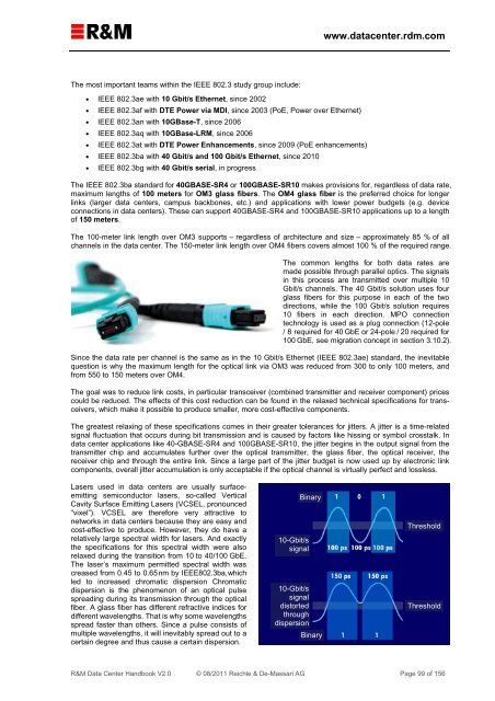
The laser’s maximum permitted spectral width was<br />
creased from 0.45 to 0.65 nm by IEEE802.3ba, which<br />
led to increased chromatic dispersion Chromatic<br />
dispersion is the phenomenon of an optical pulse<br />
spreading during its transmission through the optical<br />
fiber. A glass fiber has different refractive indices for<br />
different wavelengths. That is why some wavelengths<br />
spread faster than others. Since a pulse consists of<br />
multiple wavelengths, it will inevitably spread out to a<br />
certain degree and thus cause a certain dispersion.<br />
Binary<br />
10-Gbit/s<br />
signal<br />
10-Gbit/s<br />
signal<br />
distorted<br />
through<br />
dispersion<br />
Binary<br />
Threshold<br />
Threshold<br />
R&M <strong>Data</strong> <strong>Center</strong> <strong>Handbook</strong> V2.0 © 08/2011 Reichle & De-Massari AG Page 99 of 156