

R&M Data Center Handbook
R&M Data Center Handbook
R&M Data Center Handbook

You also want an ePaper? Increase the reach of your titles
YUMPU automatically turns print PDFs into web optimized ePapers that Google loves.
www.datacenter.rdm.com<br />
R&M provides space-spacing solutions for this purpose. So, for example, 3 patch panels can be installed in the<br />
Robust (CMS) cabinet type on both the front as well as rear 19” mounting plane, each on the left and right side of<br />
the 19” sections, as shown in the center image. By using high-density panels with 48 ports each, 288 connections<br />
can be built into in a rack of that type, in both the front and rear – and the full installation height is still available.<br />
Similarly 288 connections (copper or fiber optic) can be supported with R&M’s “Raised Floor Solution”, an underfloor<br />
distributor solution that can mount up to 6 19” patch panels (image to the right). The distributor platform is<br />
designed for raised floors (600x600 mm) and therefore allows the use of narrow racks (server racks) which in turn<br />
leads to space savings in the data center. Take care when installing these solutions that the supply of cooled air is<br />
not blocked.<br />
Cable Patches for Network Components<br />
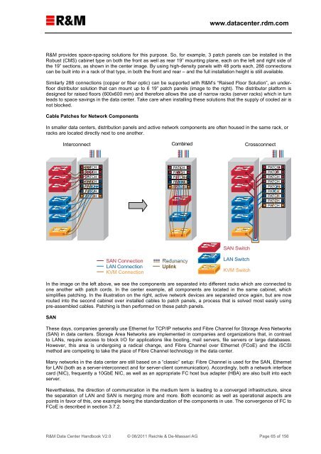
In smaller data centers, distribution panels and active network components are often housed in the same rack, or<br />
racks are located directly next to one another.<br />
Interconnect<br />
Combined<br />
Crossconnect<br />
PATCH<br />
PATCH<br />
PATCH<br />
PATCH<br />
PATCH<br />
PATCH<br />
PATCH<br />
PATCH<br />
PATCH<br />
PATCH<br />
PATCH<br />
PATCH<br />
PATCH<br />
PATCH<br />
PATCH<br />
PATCH<br />
PATCH<br />
PATCH<br />
PATCH<br />
PATCH<br />
PATCH<br />
SAN Switch<br />
SAN Connection<br />
LAN Connection<br />
KVM Connection<br />
Redunancy<br />
Uplink<br />
LAN Switch<br />
KVM Switch<br />
In the image on the left above, we see the components are separated into different racks which are connected to<br />
one another with patch cords. In the center example, all components are located in the same cabinet, which<br />
simplifies patching. In the illustration on the right, active network devices are separated once again, but are now<br />
routed into the second cabinet over installed cables to patch panels, a process that is solved most easily using<br />
pre-assembled cables. Patching is then performed on these patch panels.<br />
SAN<br />
These days, companies generally use Ethernet for TCP/IP networks and Fibre Channel for Storage Area Networks<br />
(SAN) in data centers. Storage Area Networks are implemented in companies and organizations that, in contrast<br />
to LANs, require access to block I/O for applications like booting, mail servers, file servers or large databases.<br />
However, this area is undergoing a radical change, and Fibre Channel over Ethernet (FCoE) and the iSCSI<br />
method are competing to take the place of Fibre Channel technology in the data center.<br />
Many networks in the data center are still based on a “classic” setup: Fibre Channel is used for the SAN, Ethernet<br />
for LAN (both as a server-interconnect and for server-client communication). Accordingly, both a network interface<br />
card (NIC), frequently a 10GbE NIC, as well as an appropriate FC host bus adapter (HBA) are also built into each<br />
server.<br />
Nevertheless, the direction of communication in the medium term is leading to a converged infrastructure, since<br />
the separation of LAN and SAN is merging more and more. Both economic as well as operational aspects are<br />
points in favor of this, one example being the standardization of the components in use. The convergence of FC to<br />
FCoE is described in section 3.7.2.<br />
R&M <strong>Data</strong> <strong>Center</strong> <strong>Handbook</strong> V2.0 © 08/2011 Reichle & De-Massari AG Page 65 of 156