

R&M Data Center Handbook
R&M Data Center Handbook
R&M Data Center Handbook

You also want an ePaper? Increase the reach of your titles
YUMPU automatically turns print PDFs into web optimized ePapers that Google loves.
www.datacenter.rdm.com<br />
The Cat. 7 A cable has to be newly specified with better alien crosstalk characteristics in order to improve this parameter.<br />
To illustrate this difference, this newly specified cable is referred to here as Cat. 7 B. That designation is not<br />
based on any standard, however.<br />
The key to future proof the cabling therefore lies in the specification of a new Cat. 7 B cable and not necessarily in<br />
the use of a Cat. 7 A connector system.<br />
Summary<br />
• 10GBase-T up to 100 m appears to be the limit of what is feasible for unscreened cabling.<br />
• 40GBase-T up to 100 m is technically feasible but appears to be too challenging for field use. Presumably<br />
it will be defined with reduced cable length (e.g. with 45 m PL).<br />
• 100GBase-T up to 100 m appears to be technically unfeasible.<br />
• Today's Class F A standardization does not support 40GBase-T because the specification for alien<br />
crosstalk is not stringent enough >>> a new Class F B will be needed.<br />
• It has not yet been shown that a Cat. 7 A connector system is necessary to achieve 40GBase-T.<br />
Given the uncertainties about connector system requirements, one should wait for clarification in the standardization<br />
before using Cat. 7 A connecting hardware. Cat. 7 A cables with improved alien crosstalk (Cat. 7 B) can be<br />
used to be 40GBase-T ready.<br />
3.10.6 EMC Behavior in Shielded and Unshielded Cabling Systems<br />
The motivation to once again investigate the topic of the EMC behavior of shielded and unshielded cabling, which<br />
has been examined a number of times already, is the introduction of the new application 10GBase-T.<br />
The use of ever higher order of modulation may well reduce the necessary bandwidth, but it makes the new protocols<br />
more and more susceptible to external interference. Here it is worth noting, that the separation between<br />
symbols with 10GBase-T is approximately 100x smaller than with 1000Base-T (see Figure below).<br />
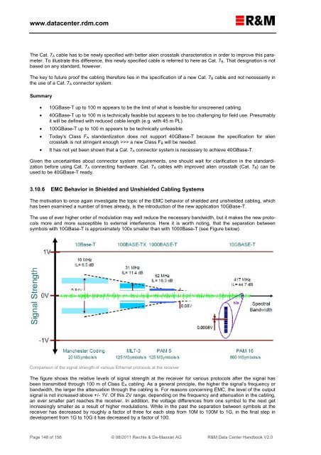
Comparison of the signal strength of various Ethernet protocols at the receiver<br />
The figure shows the relative levels of signal strength at the receiver for various protocols after the signal has<br />
been transmitted through 100 m of Class E A cabling. As a general principle, the higher the signal’s frequency or<br />
bandwidth, the larger the attenuation through the cabling is. For reasons concerning EMC, the level of the output<br />
signal is not increased above +/- 1V. Of this 2V range, depending on the frequency and attenuation in the cabling,<br />
an ever smaller part reaches the receiver. In addition, the voltage differences from one symbol to the next get<br />
increasingly smaller as a result of higher modulations. While in the past the separation between symbols at the<br />
receiver has decreased by roughly a factor of three for each step from 10M to 100M to 1G, in the final step in<br />
development from 1G to 10G it has decreased by a factor of 100.<br />
Page 148 of 156 © 08/2011 Reichle & De-Massari AG R&M <strong>Data</strong> <strong>Center</strong> <strong>Handbook</strong> V2.0